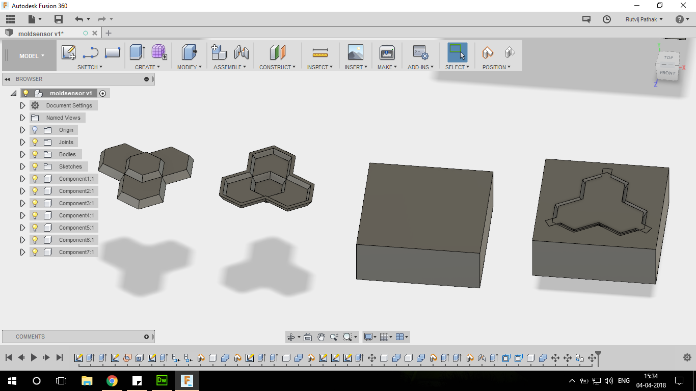
Fusion Design for making a mold
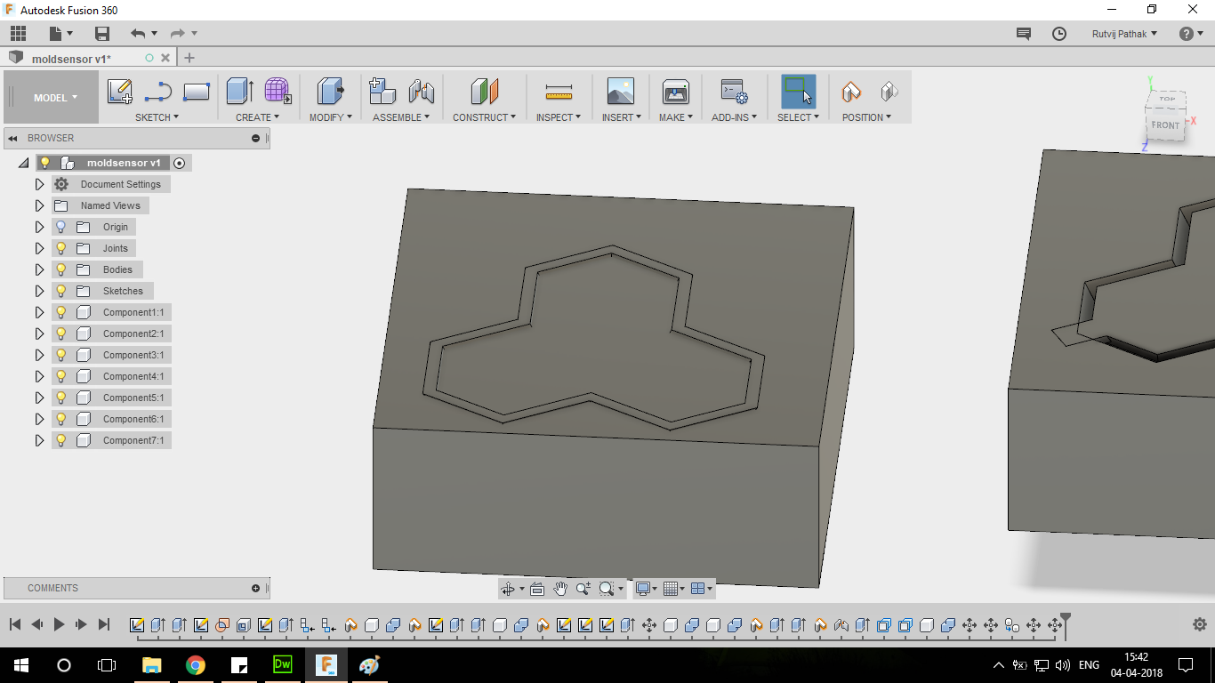
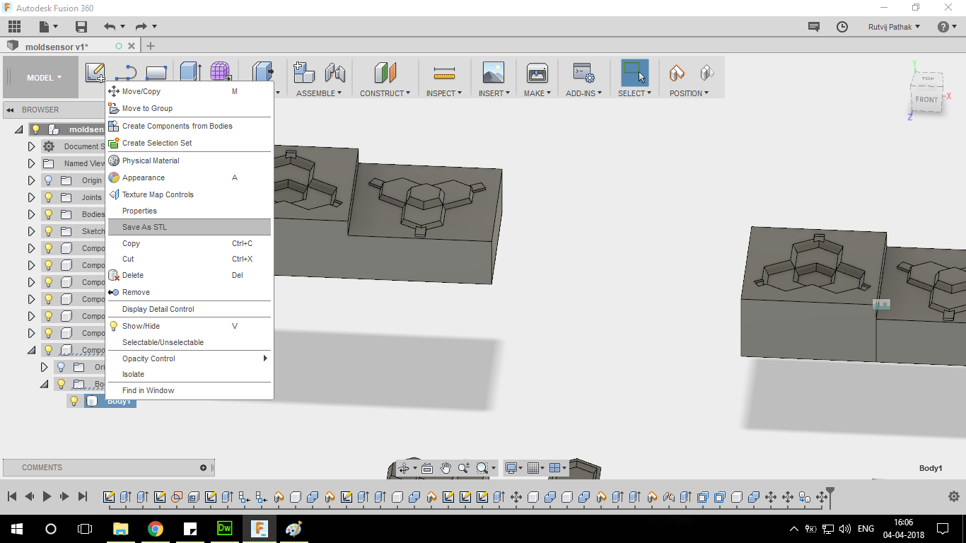
Aligning the part to be cut from the stock
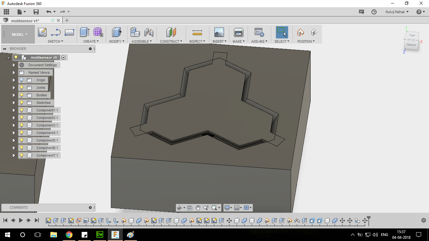
Empty space generated between 2 molds . 3 tabs generated to hold the top part of the mold in place during curing
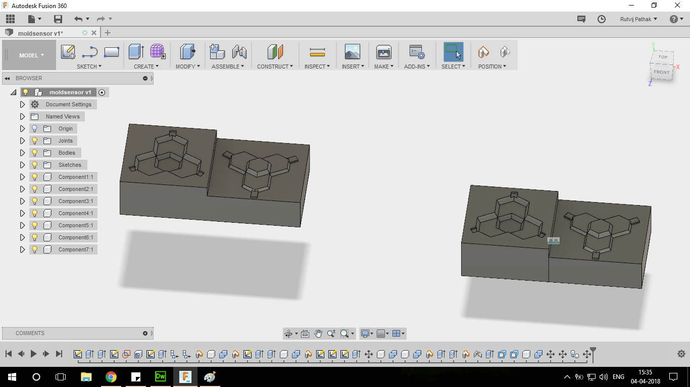
Joining the two halves because everytime Fusion360 cuts parts there is the original parts this allows us to keep the original part and the new combined part . This is extremely helpful when we need to create stl files .
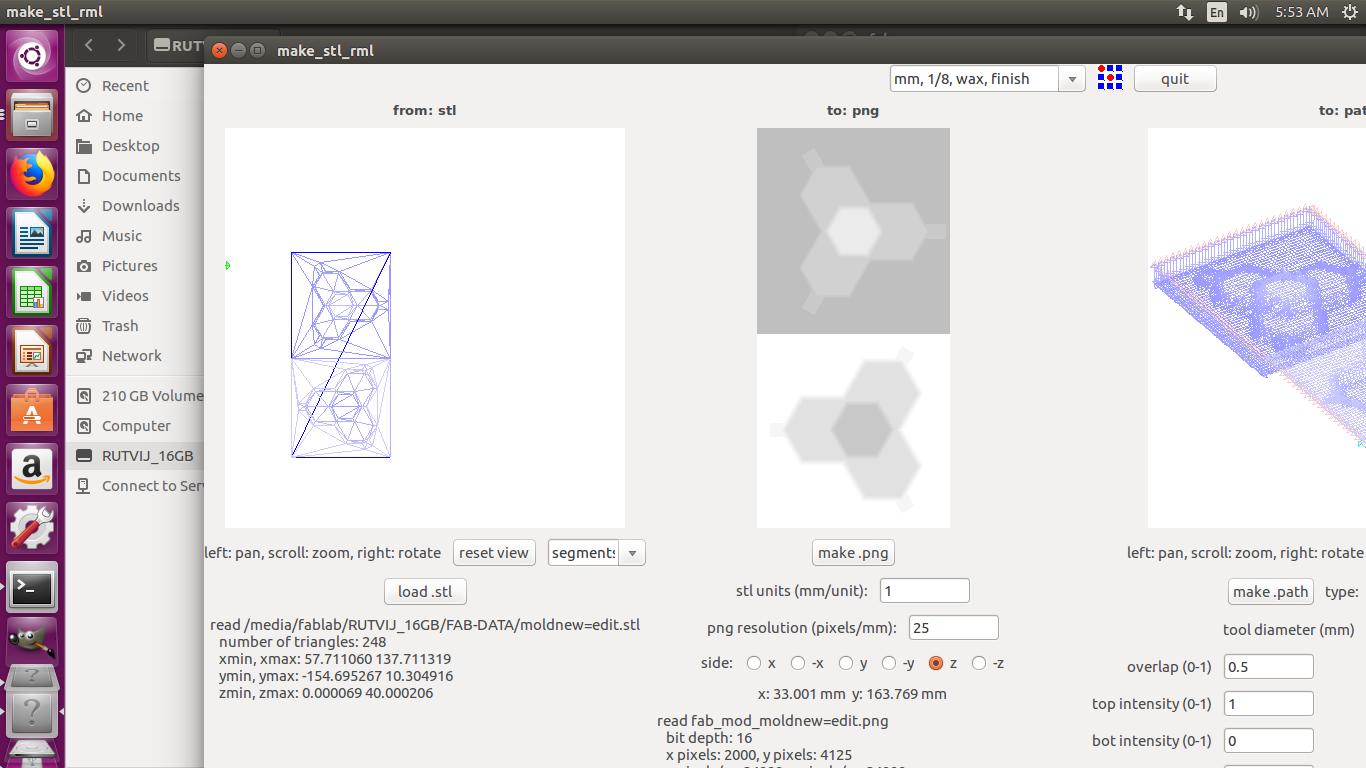
Screenshot of after loading the stl file in MODs Setup
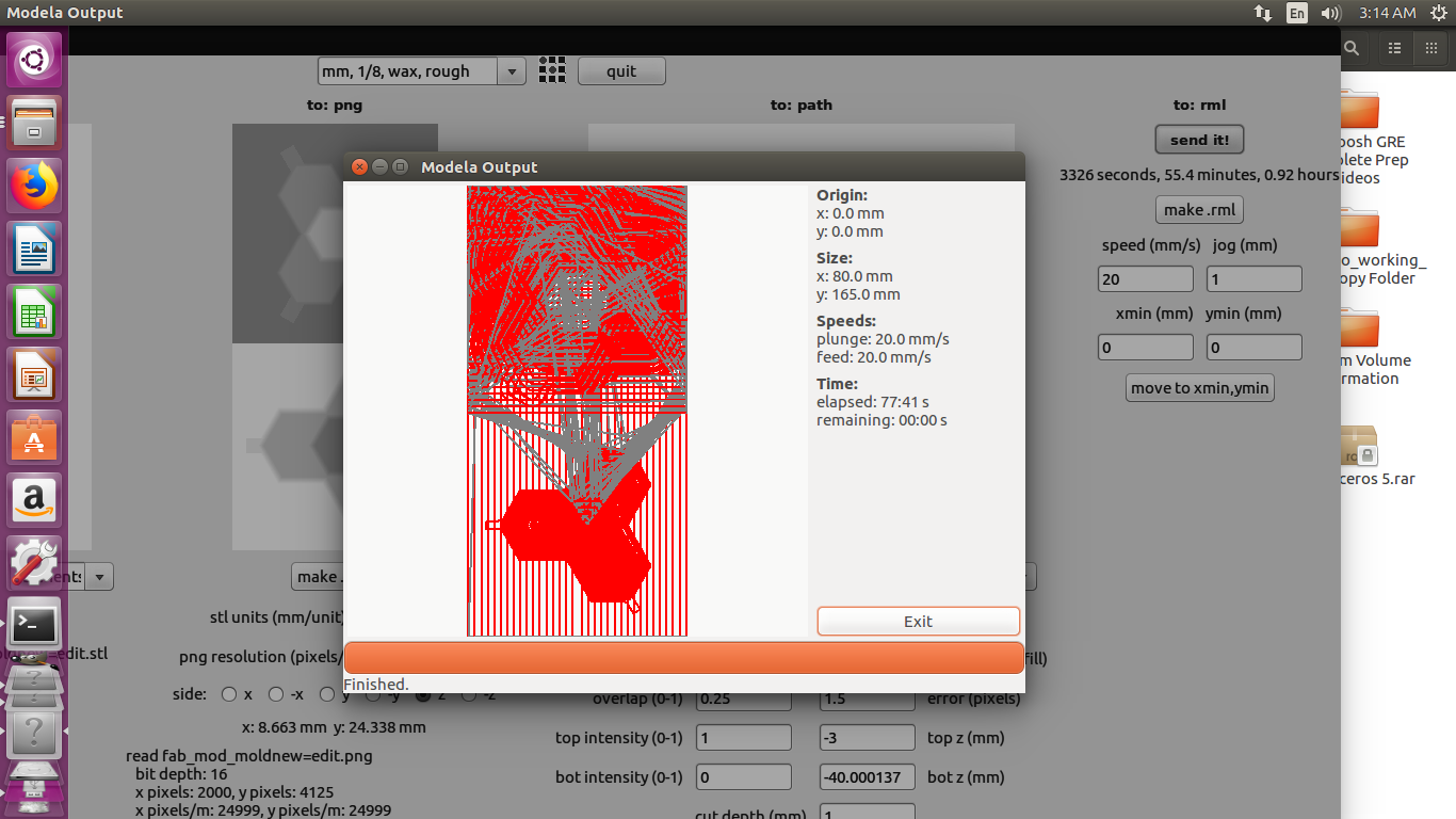
Path generated for milling the components
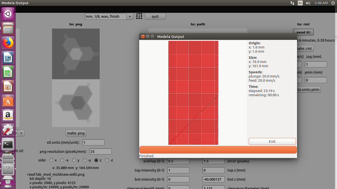
Finishing path of the components
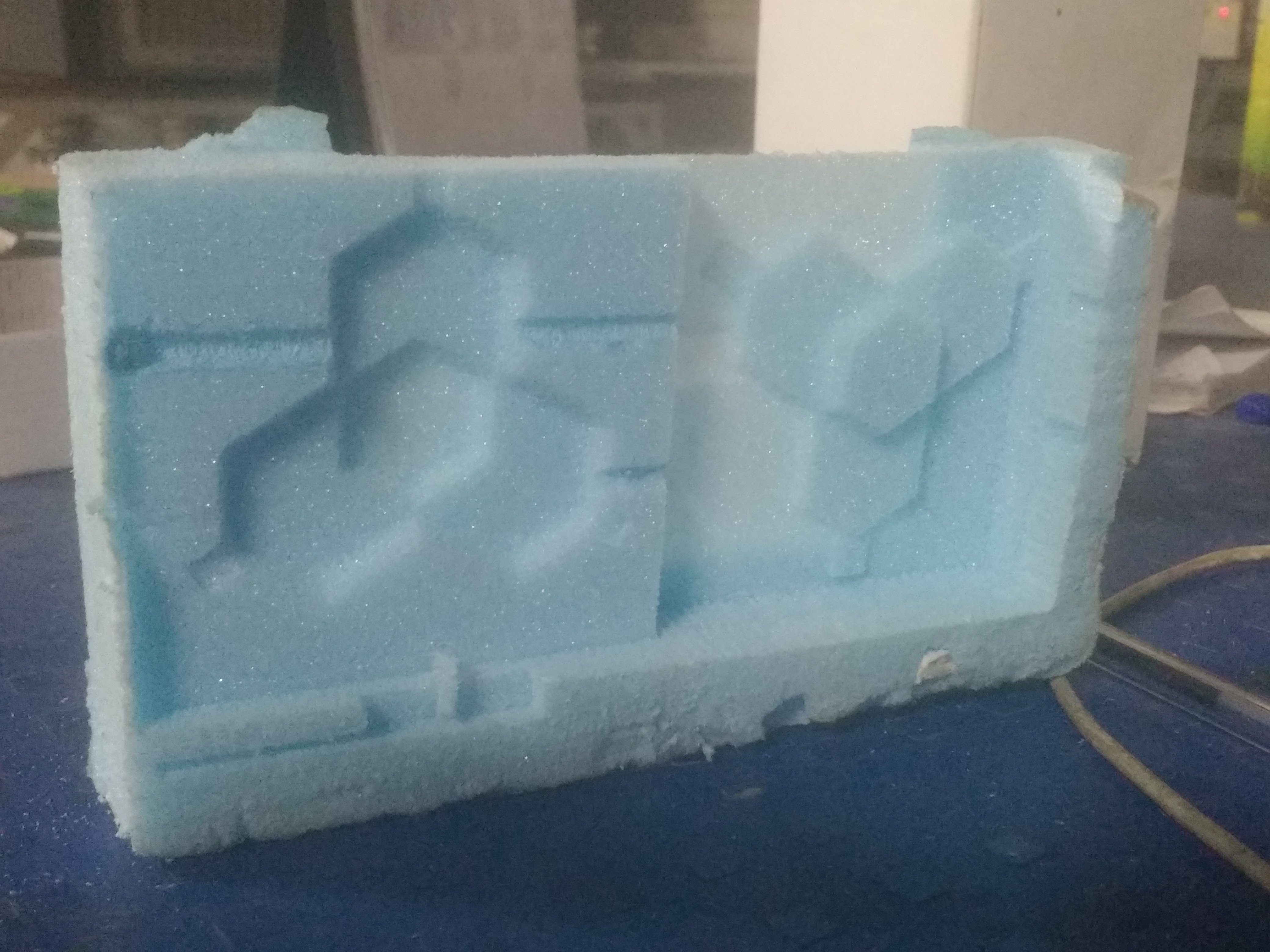
Milled Foam along the inside and outside shells
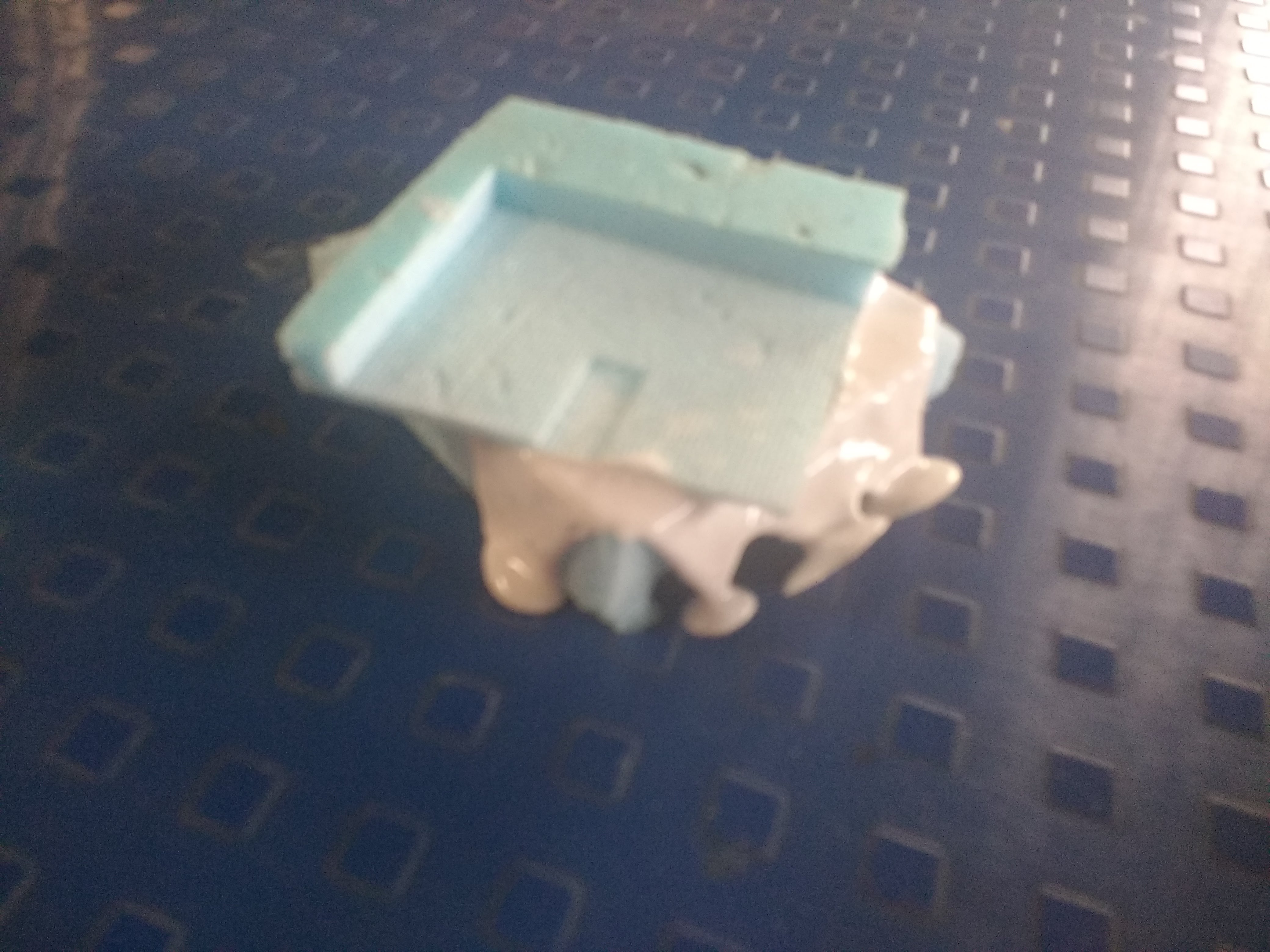
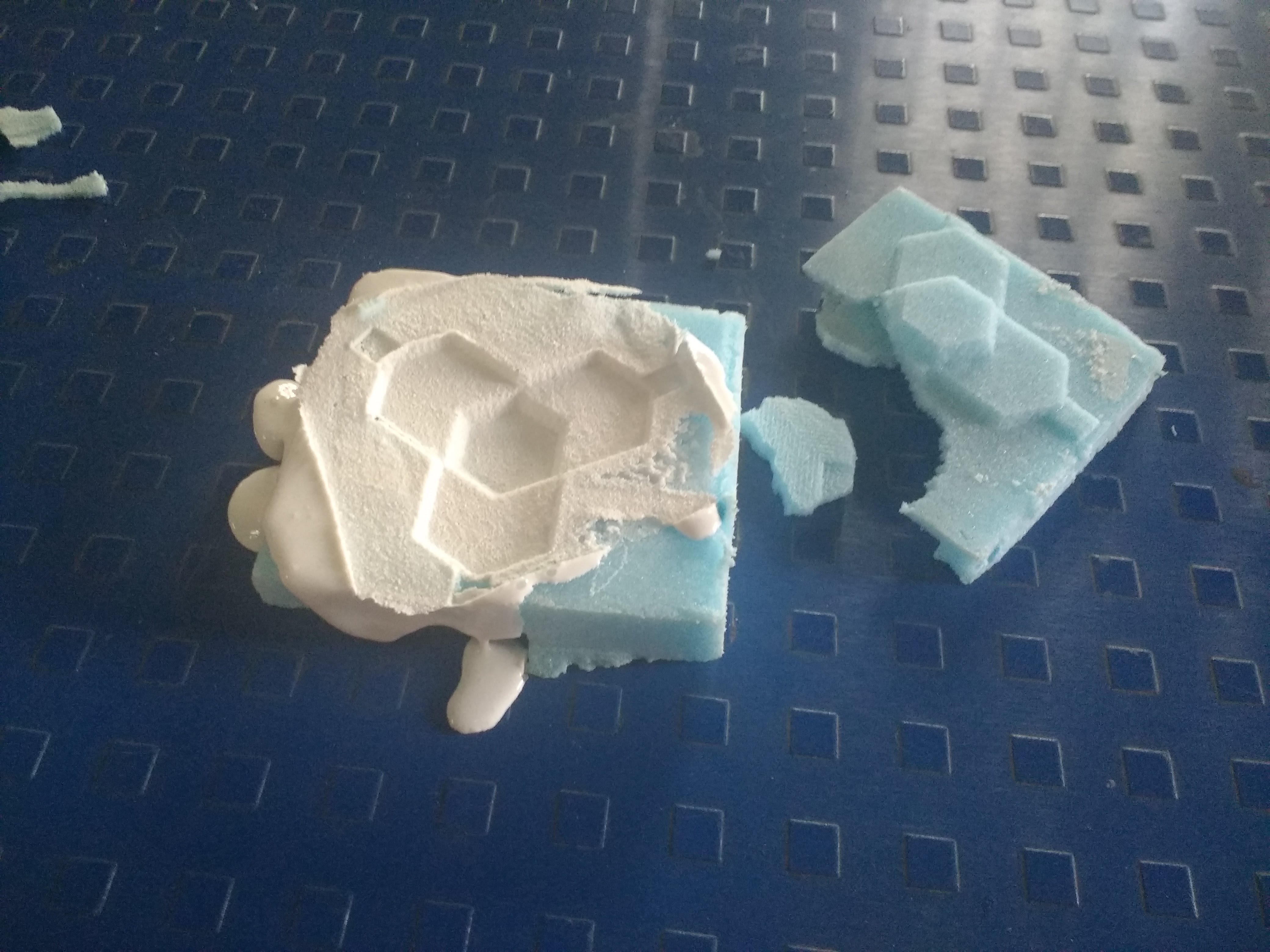
After removing the top part of the mold . Notice the texture of the removed mold
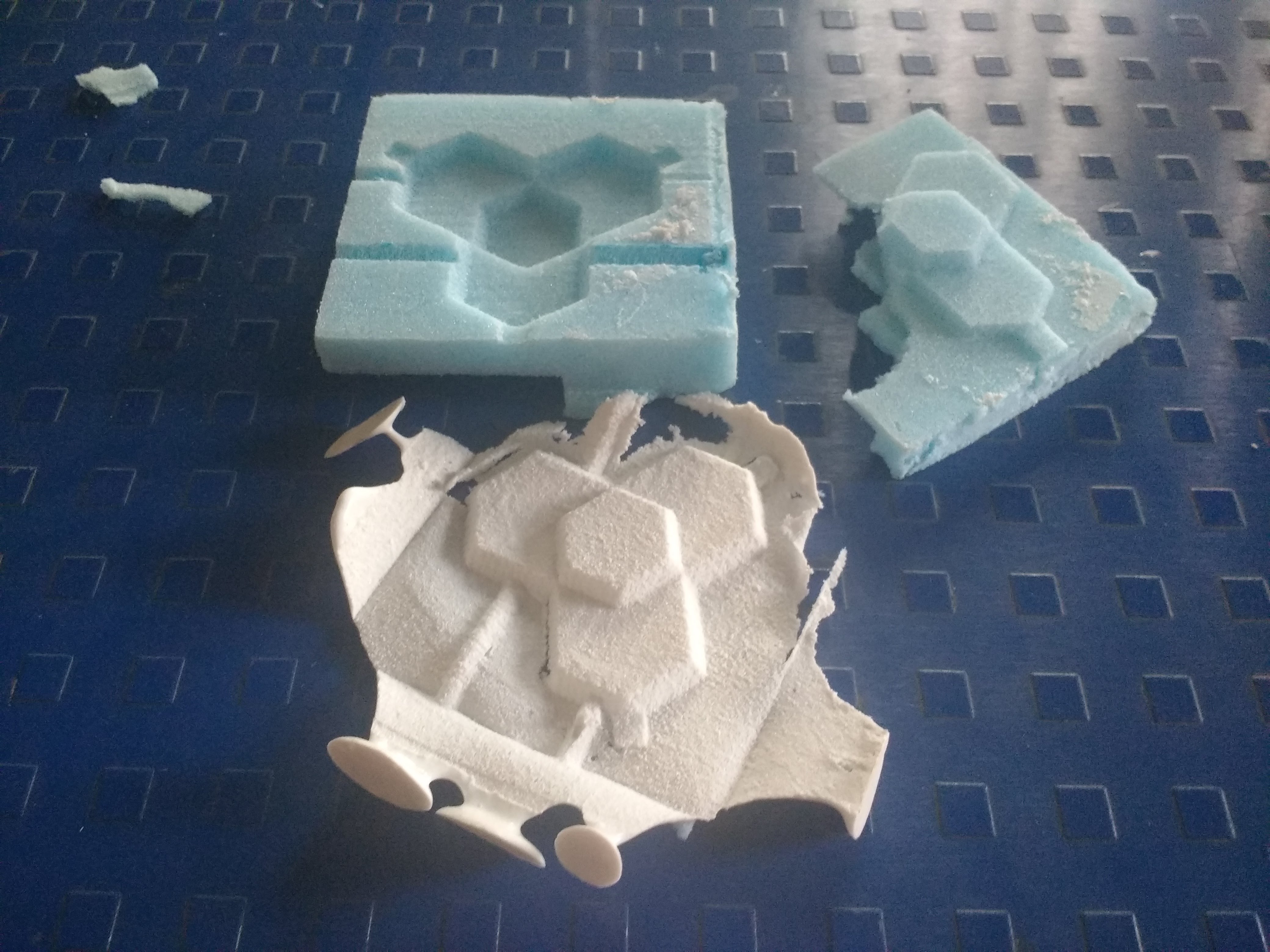
Silicone rubber cast removed from both the molds .
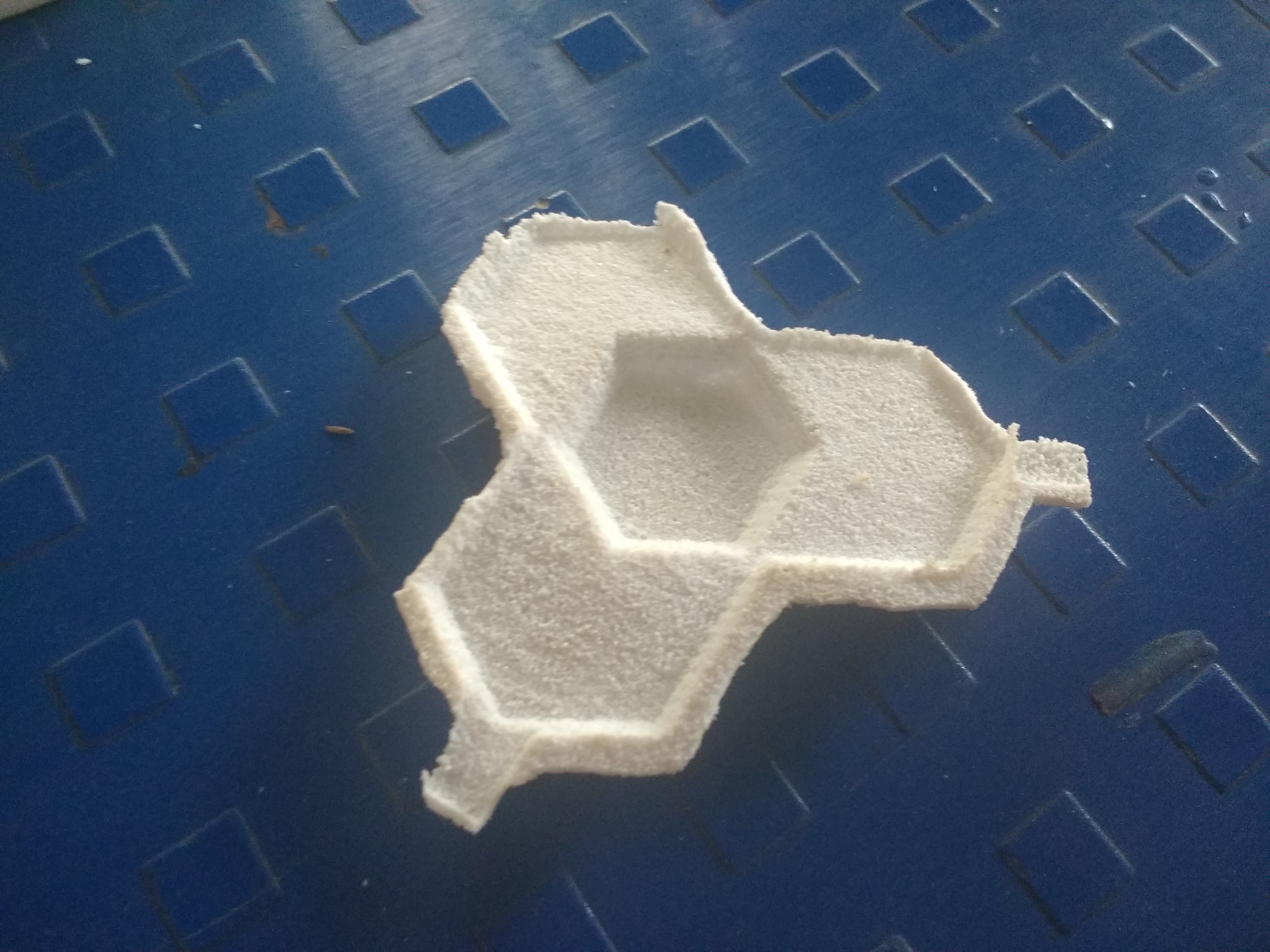
Extra parts of the cast are cut in order to obtain the final casting
Following design was not used as it does not follow the 3 step mold process required for the academy . As this mold was wrong as there was not way i could pour the mold . Thus rendering the milling wrong
UPDATE :
We have used Modlsil 100 which is a locally made silicon rubber solution.
" Moldsil-100 is a premium grade condensation curing type medium viscosity Silicone RTV, recommended for mold making applications. This is a lowable grade, having high mechanical strength and cures with various catalyst options (depending on the application requirements) at room temperature to a flexible elastomer, well suited for detailed and exact reproduction of artifacts, figures, architectural items and similar" - Moldsil Website
The technical information regarding MOldsil can be found here : link
The machinable wax block which was used is called " Ferris® File-A-Wax® "
More information about the wax can be found here : link
Safety Datasheet of the Wax can be found here : link
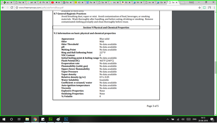
After reading this datasheet they have cautioned the user when handling the wax when it is hot . The most important of the parameter i found was the melting point of the wax was 227 deg F which is 108 deg celsius . This allowed me to cure the wax in the oven at a temperature of 60 deg celsius
This design is basically a diffusion lens for my leds and will be used in my final project.
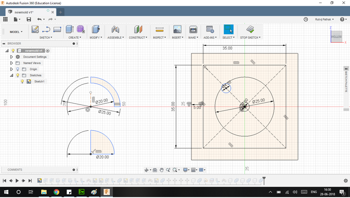
This is the 2D planar sketch which was used to extrude . Mainly revolve command was used to create the hemispheres
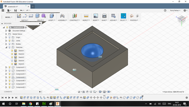
This is the inside part of the lens .
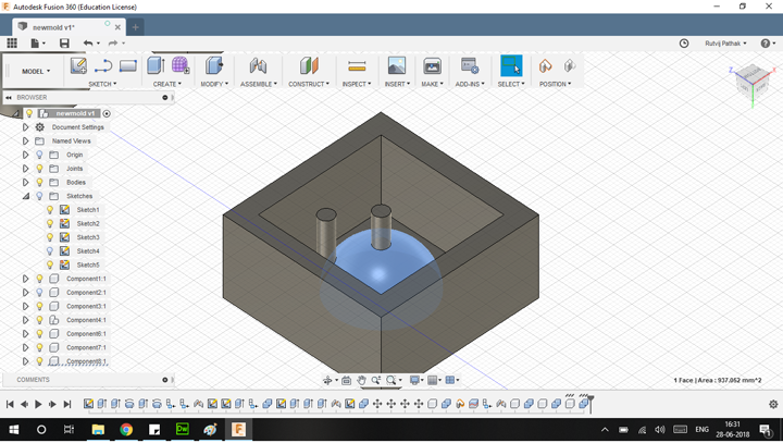
This is the outside part of the mold i.e which will generate the outside part of the mold . I added 2 pillars for pouring and another hole for air .
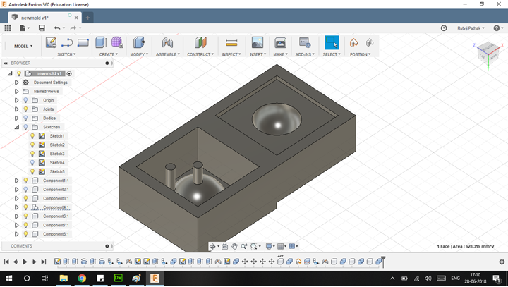
I combined these 2 molds to form the the single stl file which will be cut with the 1/8 inch rough cut to generate the steps which will produce diffusion
Instead modelling the steps in the hemispherical design i used the rough cut setting to automaticall generate the steps
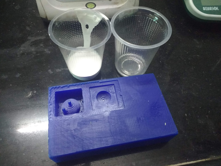
This is after filling the molds with silicon rubber solution .Ratios used were 1 : 10 i.e hardner as to silicone . Notice the steps generated
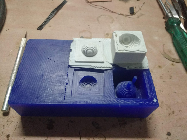
The mold which after it was done curing . I was cured in an oven at 60 deg centrigrade
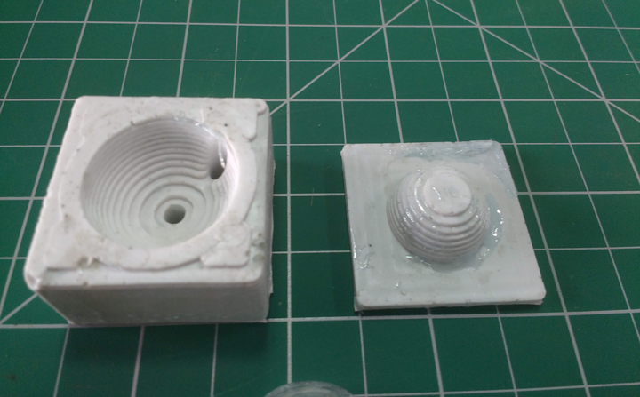
Mold after the extra parts have been cut of from the sides
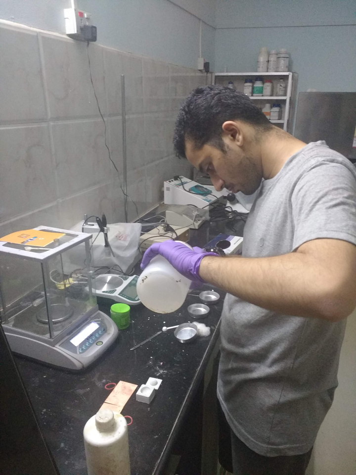
I mixed epoxy with the hardner in proportion of 1:2 i.e 1 part hardner to 2 parts of epoxy
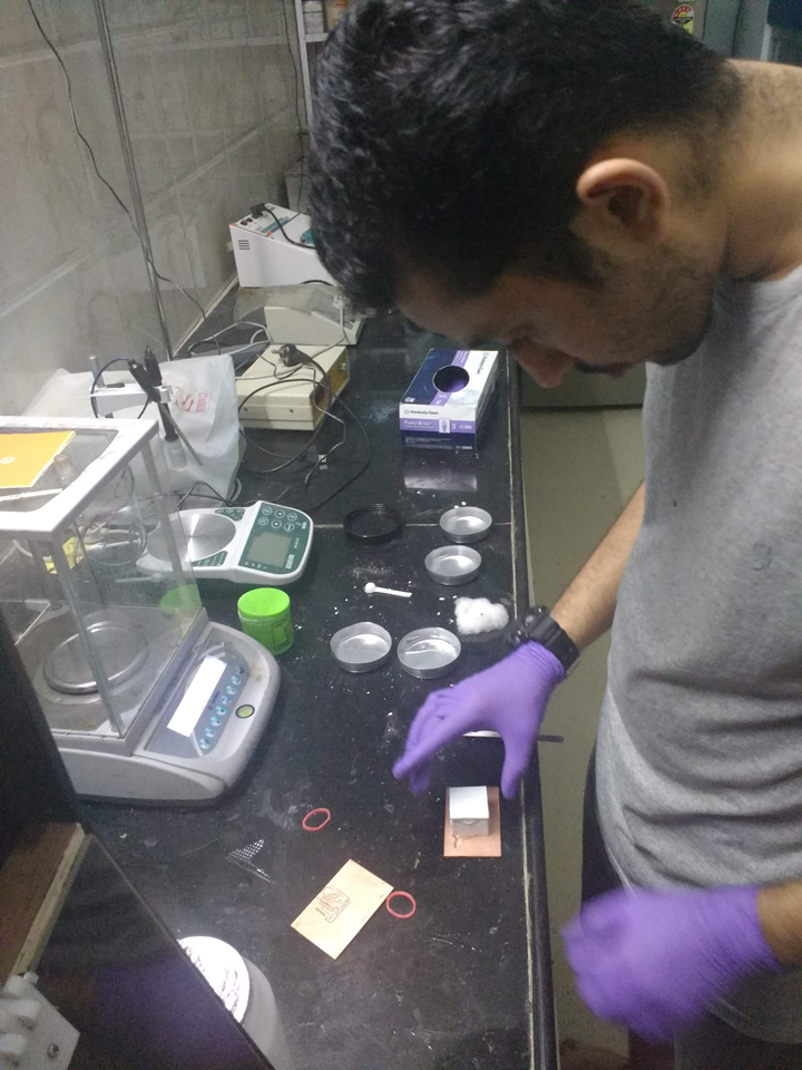
Closing the mold from the top
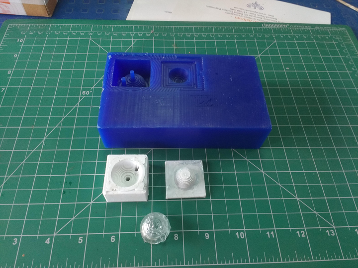
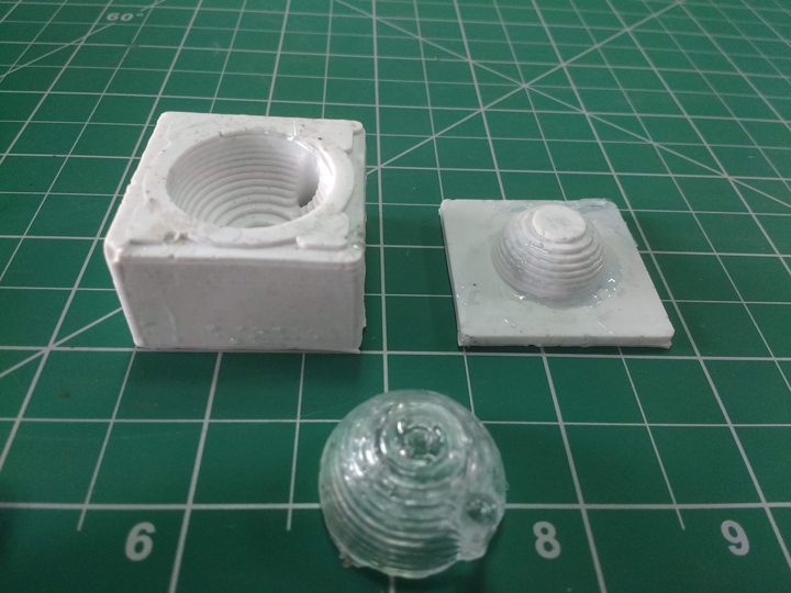
Mold and the cast of epoxy (There are small bubbles in the cast due to improper plunging process)
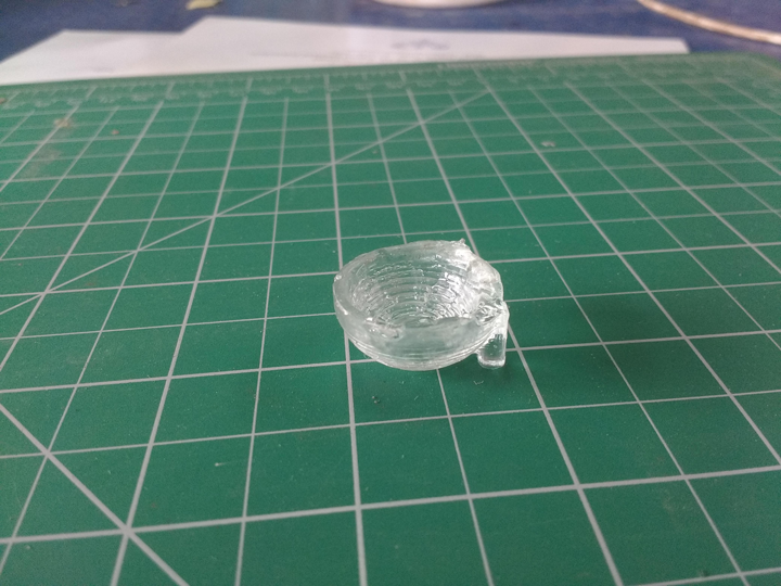
The top edge of the lens has a ragged edge . This indicates that the mold was not properly filled
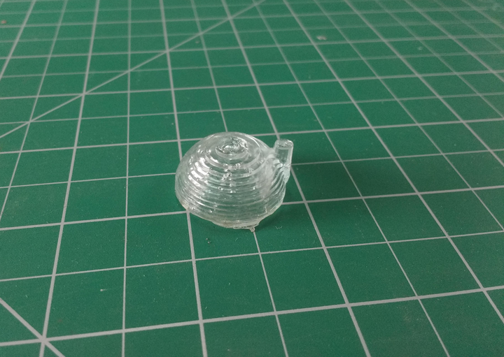
Outside surface of lens came out quite nice . The steps of the cast will further lead to greater diffusion from the LED
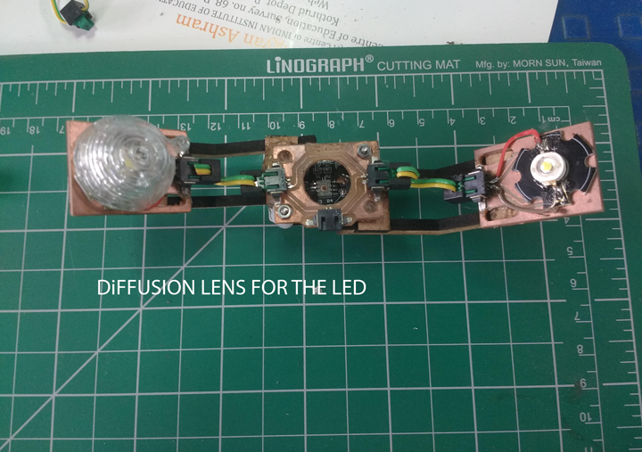
Finaly mounting the diffusion lens on top of the lED
This summarises the progress for this week in Molding and Casting
All original files can be found here