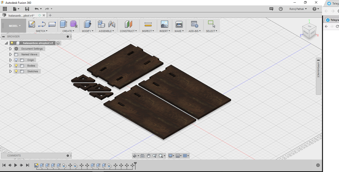
This is the Fusion file for the HalasanBox design . This was nested in this design itself . But due to the older version of the partworks i had to generate the pdf files of these files from DXF .
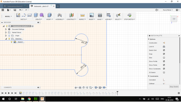
This is the sketch of the box where dogbone fillets added to make sure the corners are cut well.
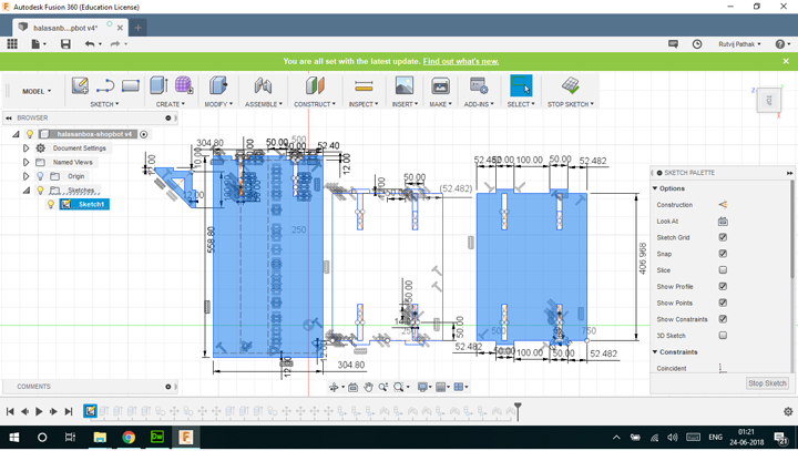
THis is the sketch which is used as the base of the dxf . I designed it in Fusion360 using basic sketch geometry.
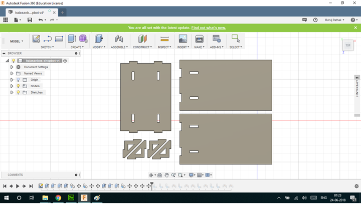
This is the bodies which have been generated from the sketch components.
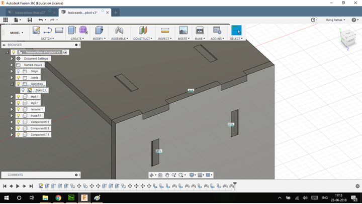
This is the joints of this stool . This the one dimensional joint which were designed to be used with a flat stock such as Plywood .
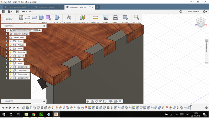
This is the original joint which was designed for a 1 inch thick piece of wood stock . These dovetails joints will make constraining the joints in 2 axis . This is the simpler and aesthetic looking design.
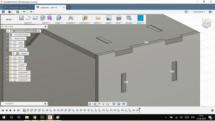
This is the redesigned joint to be used for a flat plywood . This joints has to be further constrained using screws . The 3d joint couldnt not be used on the shopbot which was available at COEP because the 3D part of the PartWorks Software was not supported .
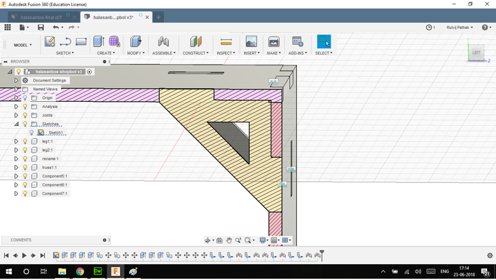
These are the trusses to provide strenght to the joint . This is the sectional analysis of the stool .
For wood, the rule for cut depth is 1/2 of the tool diameter . For the tool in our case 1/4" the cut depth is 1/8".
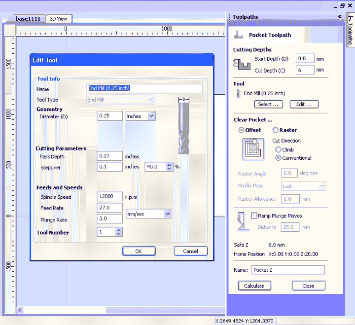
This is the endmill setting for partworks software which was the endmill which was available in the COEP Fablab
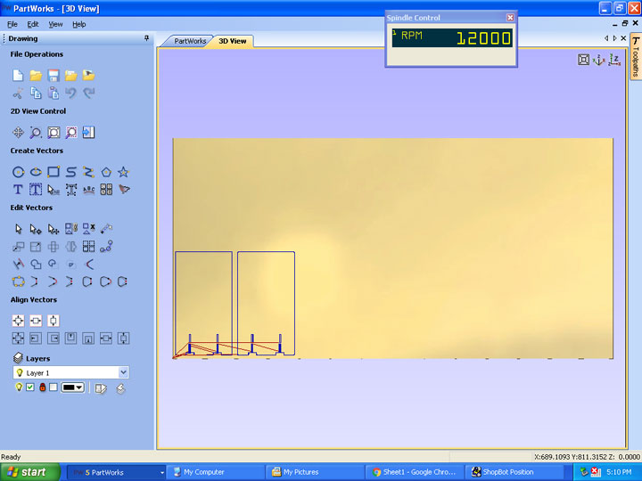
This is the screenshot of the toolpath which was generated for cutting the outside of the stock. This is the outside cut which makes sure the cut of this stock .
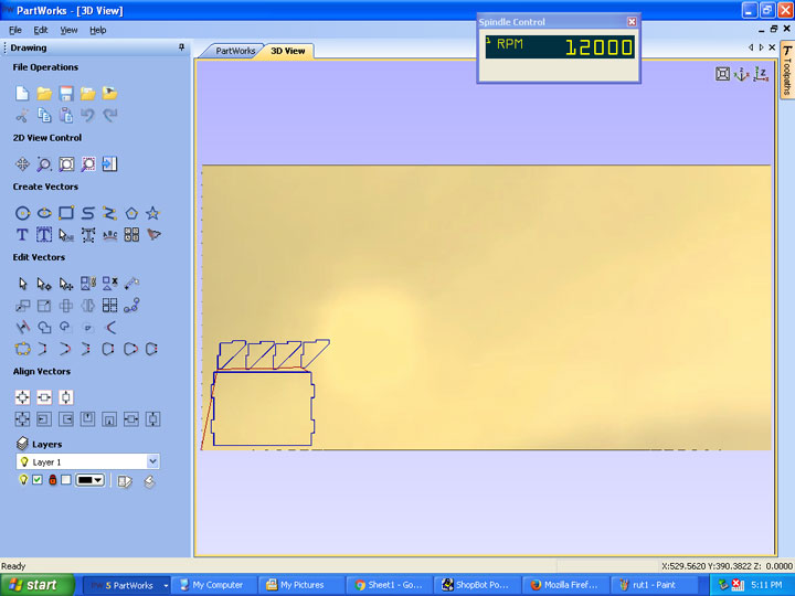
This is the screenshot of a different toolpath .(Cut Pattern) . The cut selected is also outside cut .
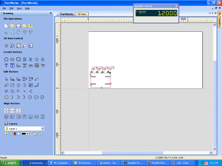
This is the cut pattern along with the speed indicator at the top . This again is the outside cut in this design .
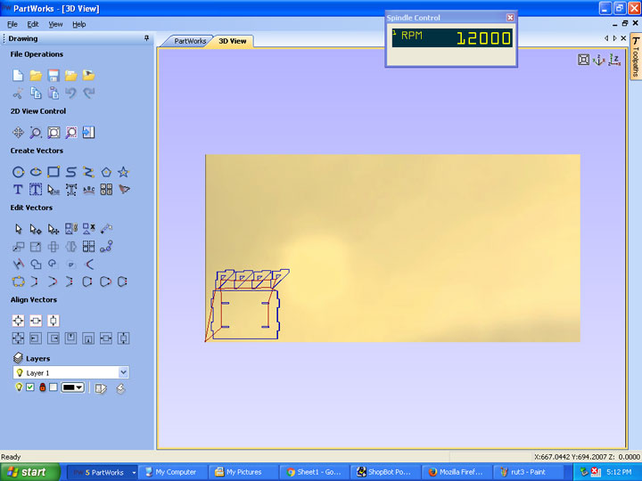
This is the ( inside ) cut which is used to generate the pocket inside the design of this file . The inside cut is also called the pocket .
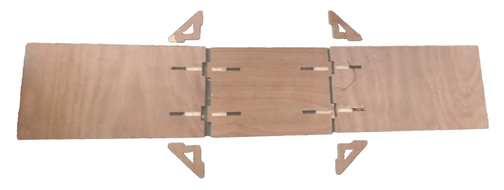
THis is the flat pack pattern for the halasan box assembly . The Assembly cut laid out flat .
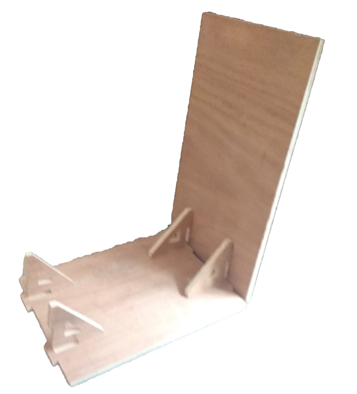
This is the basic assembly.
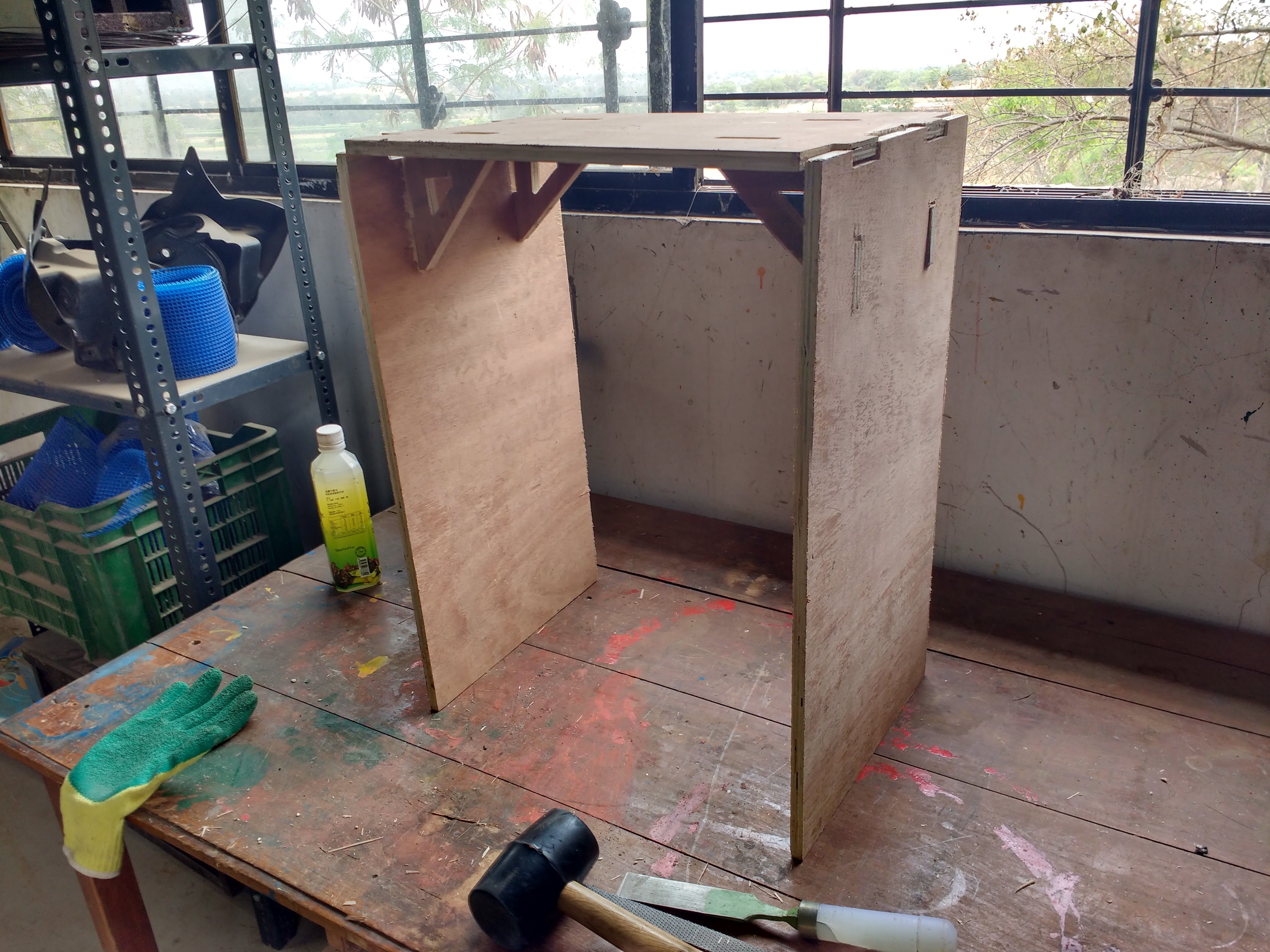
Heroshot .During improper kerfing . There were some edges that were off by 1 mm .
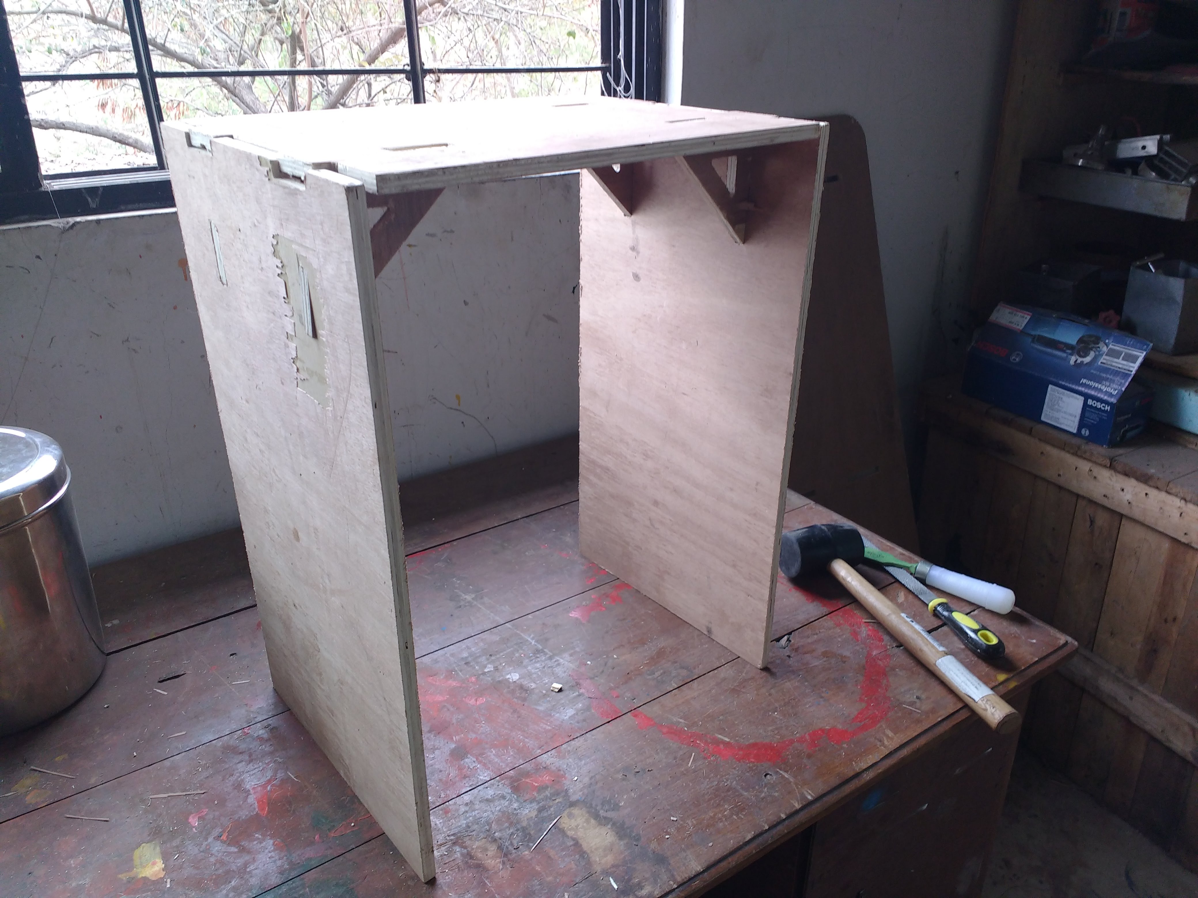
This is the final assembly of the halasan box . This Halasan Box is is now ready to use .
Personal Learning Milestones :
Learned about computer controlled machining . Learnt the importance of Speeds and feeds .The orignal files can be found here