WEEK 6 - ELECTRONICS DESIGN
This week is redesigning the Neil's Hello World Board . This board is designed around ATTiny44 . The following datasheet . Datasheet is the one of the most important documents .
Reading the Datasheet of the IC
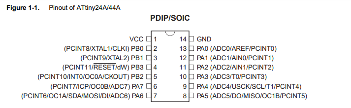
This is the datasheet of Attiny44 . This datasheet shows the pinout diagram of the IC .This is useful as this image shows all the alternate functions of the IC . This maps the schematic pins of the IC to the physical pins of the IC
One more datasheet notation
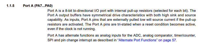
This is the port function notation in the datasheet . This also contains the pin mapping functions to its indivisual pins
Designing the Board
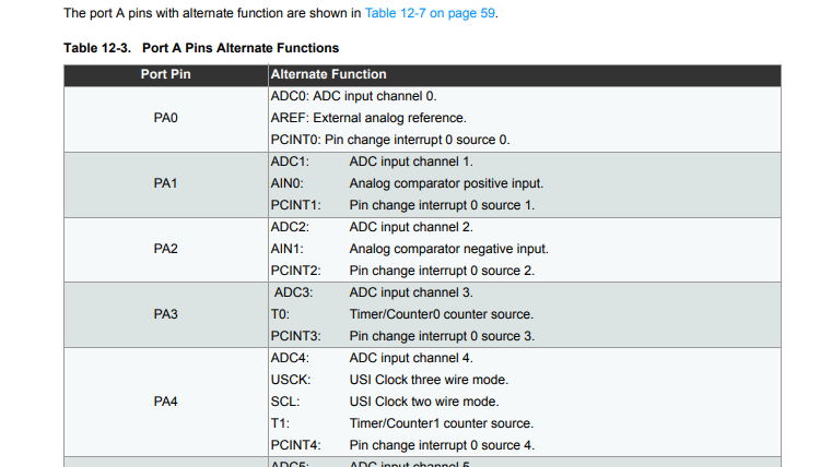
This image illustrates adding the eagle library in Eagle 9.0.0 . You need to ADD> library manager > browse for the "lbr" file
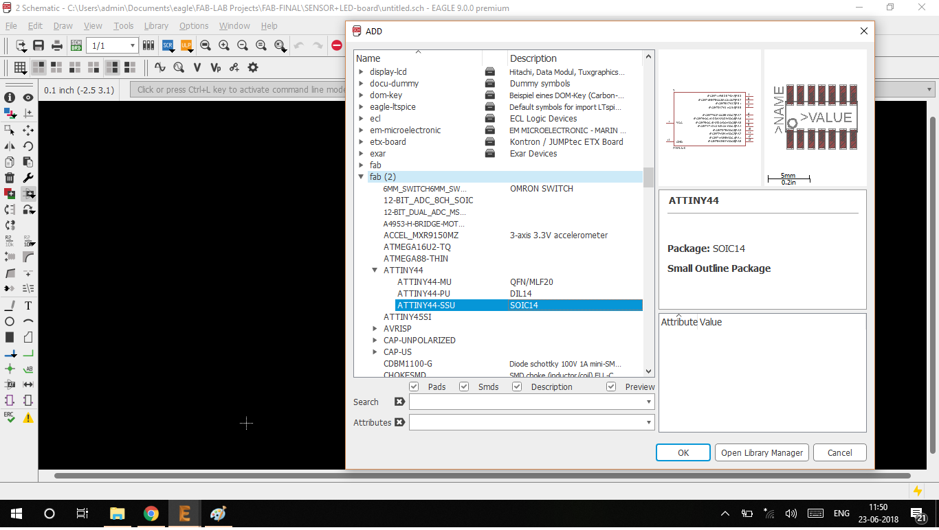
This is pop-up which comes up when adding part from the library .
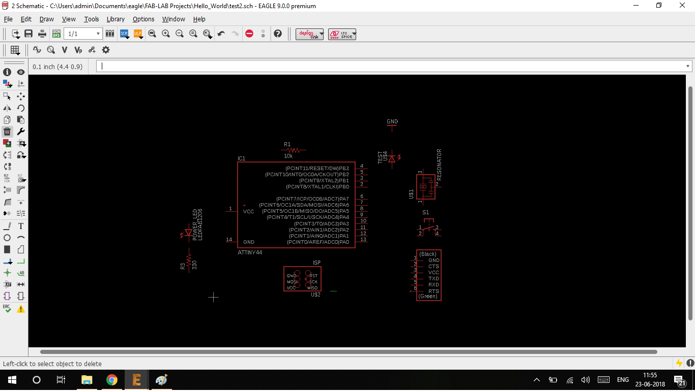
Placing the components in the schematic editor .
The easiest ways to route a schematic is to name the pins of the components. After naming the nets they are automatically connected to each other . This allows the schematic to be clean and clear . If you connect in this way the schematic is easier to debug .
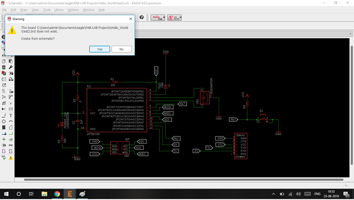
The screenshot shows the pop-up which then generates a board from the schematic .
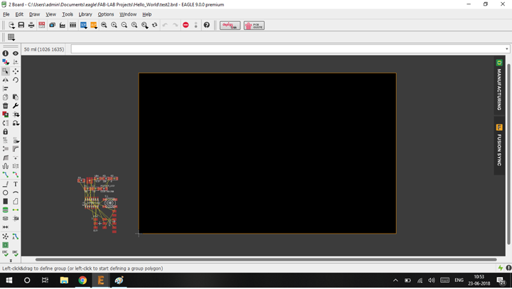
The generated board from the schematic
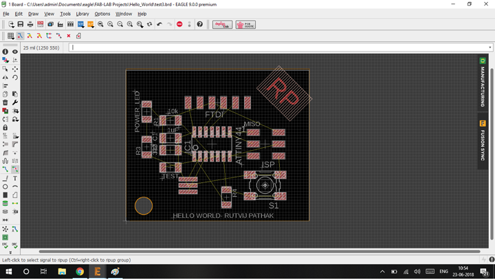
Placing the components to make sure most of the airwires are uncrossed and the components are evenly placed
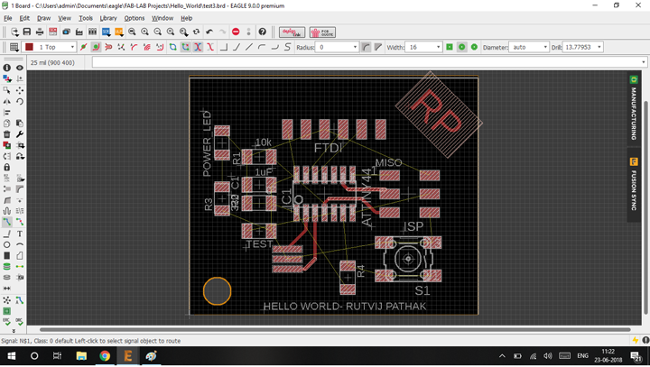
Routing the components with 16 mil width
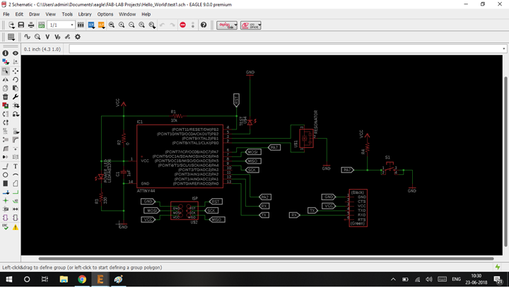
Final schematic of the helloworld board
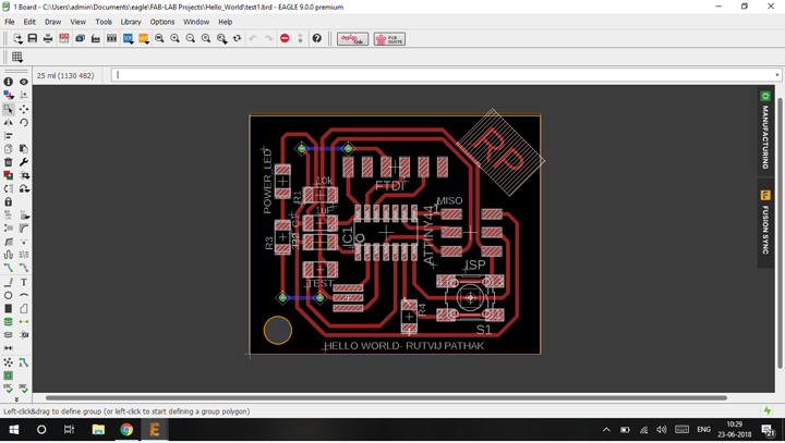
Final board of the helloworld board
Design Rule Check
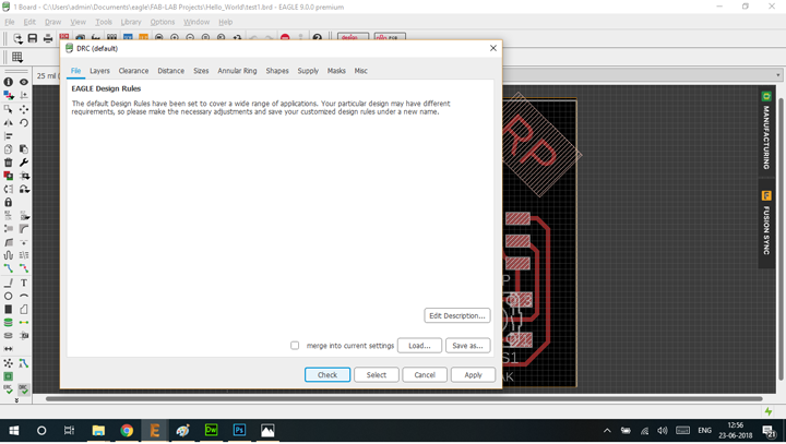
Open the DRC check from the file menu . This is the DRC window which allows you to define the contraints of the manufacturing process
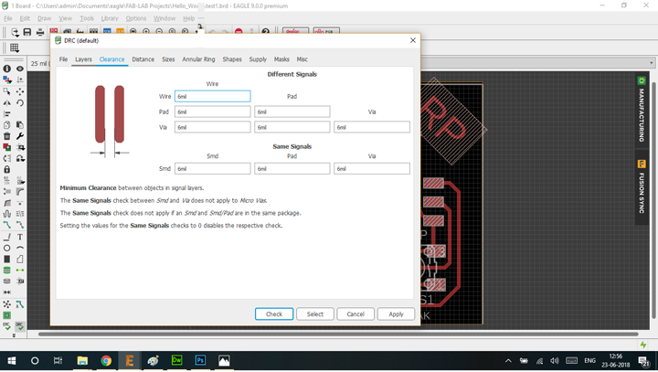
Following is the minimum width between traces which are OK on the board which is designed

After running the DRC check . It generates either warnings , errors and some errors which can be approved are also . In the following photo the airwires are being shown as unconnected , this is error is there because I put a jumper using a 0 ohm resistor.
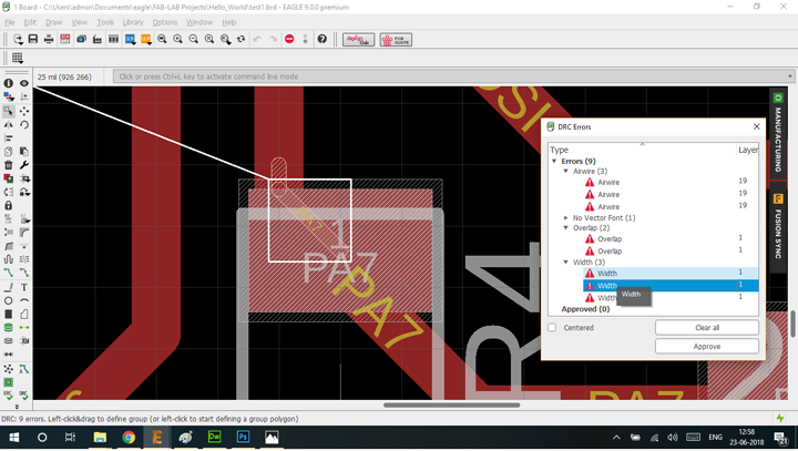
This is the overlap of traces which also highlighted in the DRC check .
Produced Board
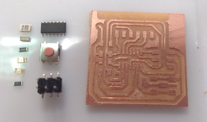
This is the milled board with all the components to be soldered
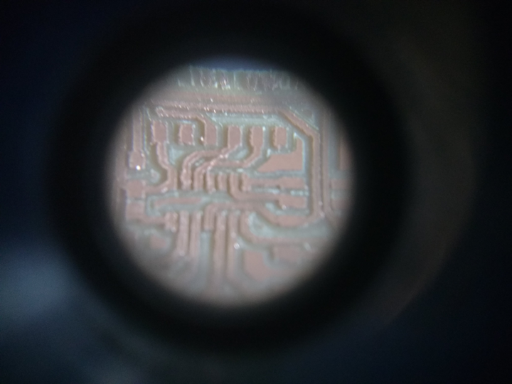
This is the closeup of the milled board which shows the scragly bits due to improper bits and powersupply issues
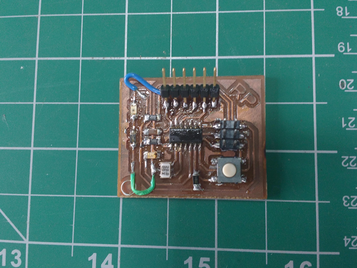
Final board which has been soldered and done
The orignal files can be found here