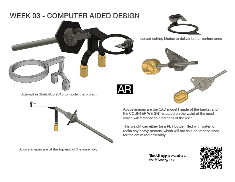
This summarises the progress for this week in CAD
TIP : The app does not have a close button ,application can be closed directly from the multitasking window

This summarises the progress for this week in CAD
TIP : The app does not have a close button ,application can be closed directly from the multitasking window
This week documents chronologically the exploration of various Design and CAD packages
Software I learned was Photoshop a raster development tool , which is used by Adobe. I used the magic wand tool to remove the background of the photos which is one of the tools I found out for the Fab-Academy as the magic allows for easier content preparation . I thinks this is one of the most important tools in this suite . I also learned the adjusting the levels of the picture to adjust the hue , colour saturation in the photo as this is extremely useful in scanning sketches as it easily allows to remove the blemishes of the paper .These blemishes are often picked up in scanner when the paper put in the scanner is not exactly smooth and plain . This creates creases which then cast shadows when the scanner moves over them .
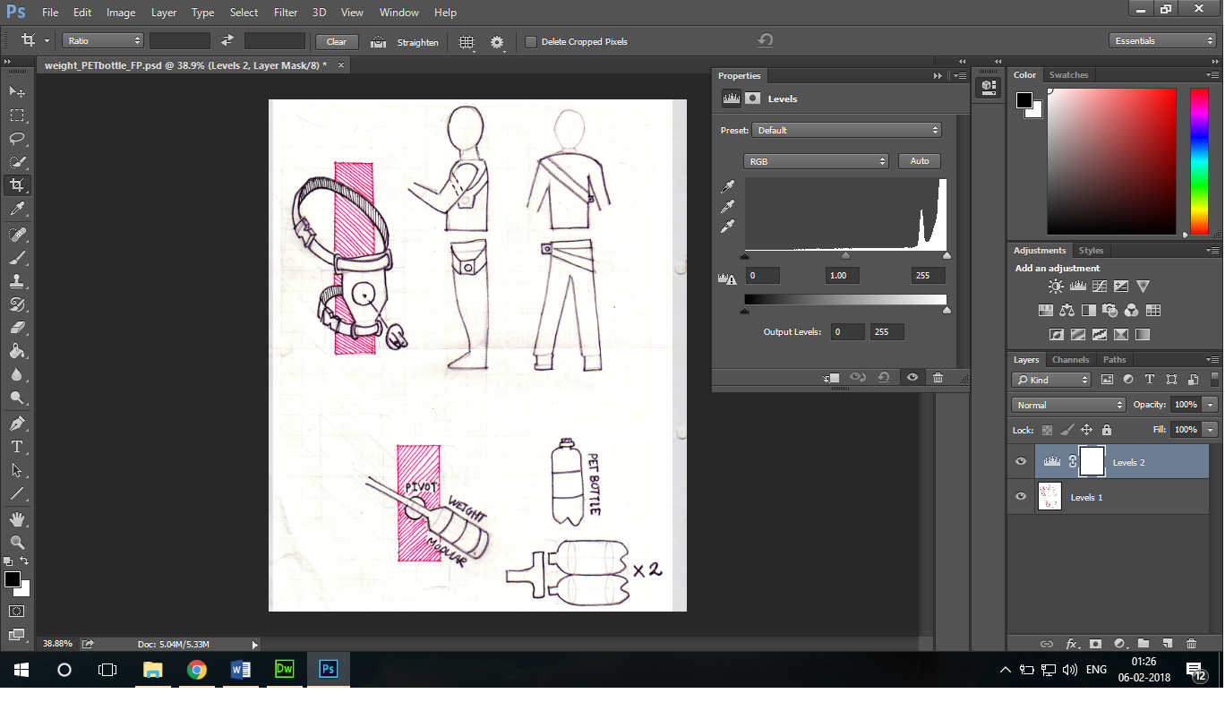
The image above shows the "raw " scan of the paper sketches
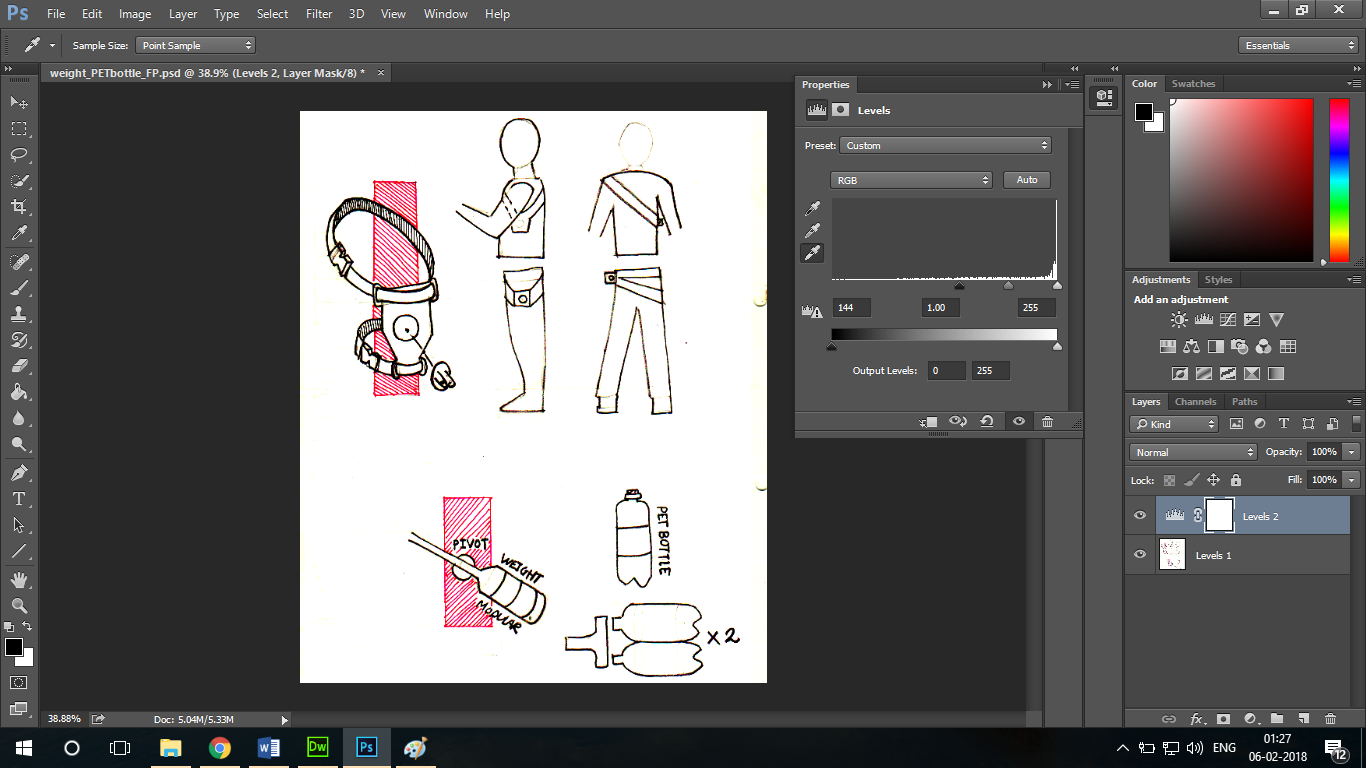
The image above shows the "processed " scan of the paper sketches which eliminates the shadows etc. Thes blemishes of the paper can be easy removed using the levels tools in photoshop . This tool allows you to manually choose the
whitest part on the paper . THis is the point which can be selected as the one of the dark parts that make all the other parts whitest in the comparison. Cleaning up the image in the process .
This is another vector based utlilitly . This is used to manupulating vectors and also offers some raster functionality . Inkscape is easy and free to use . Inkscape offers various functionalities which are mostly due to its huge extension basis which will allow you to generate various knobs and scales . In the example below , I have used the "foldable box" extension which is used to generate a foldable paper box by defining the dimensions
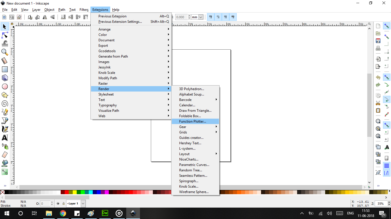
This is the extension GUI and extension window of Inkscape . Notice the various varietie and range of extension available in Inkscape.
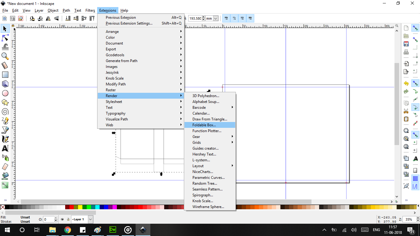
Selecting the Folable box extension among various extensions . These extensions are in the 2D . these scipts are quite helpful .
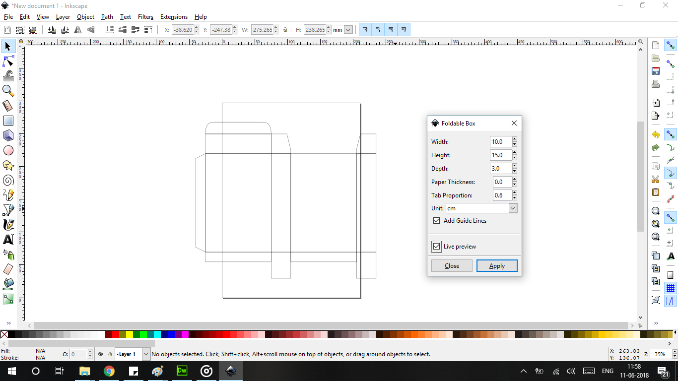
Foldabe box is generated and can be exported into any CAD or Laser Cutter program .
The levels of photo suggest that levels of the whitest of the white and the blackest of the black. This helps in eliminating the various imperfections .
Fusion 360 is all encompassing platform with 2d and 3d workspace. This allows for the constraint to be defined. Such as midpoint , tangent , parallel etc. . The sketches can easily be exported to “dxf” to be used in laser cutting exercises. For parametric portion of the CAD is choose to go with OpenSCAD as it is and easy and lightweight CAD program .which can be programmed to generate forms. I used SCAD to generate gears of various dimensions and shapes. OpenSCAD offers the option of exporting the gear in STL. Importing the STL caused the model to have irregular mesh which was suitable to be worked with. After finding various ways of exporting dxf using OpenSCAD . I found a small script to slice the model and export the dxf to be worked on further in a feature rich CAD package .
,
Sketchup allows to draw in 2d and allows the sketches to be extruded in 3d space. Illustrated below is my attempt at sketching and extruding the final project. As seen from the above pictures. Sketchup also contains various Boolean operations in this cad package. This is good begineers tools to understand the basics of CAD . The interface is simple and easy to use . SketchUp2016 has a addon rendering package which will render the given objects photorealistically .
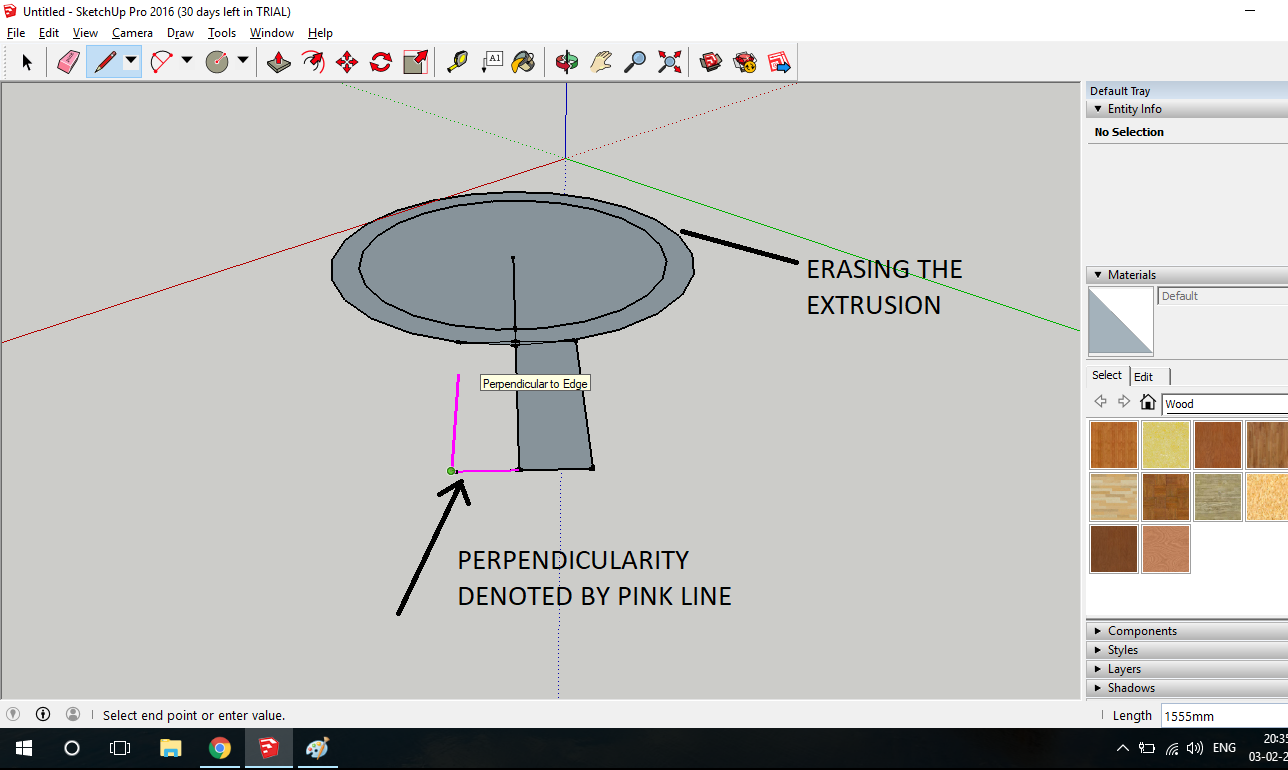
Working . Sketchup has basic constraints i.e perpendicular
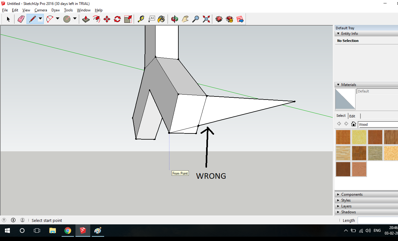
SketchUp only has 3 basic planes which is used for skectching . Thus sketching on curved planes and profiles makes it difficult
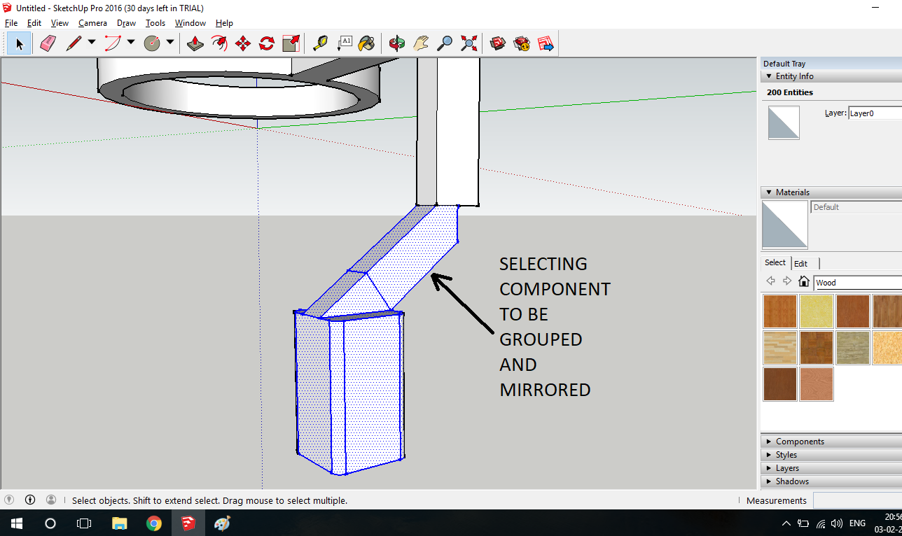
SketchUp supports basic grouping and mirroring commands
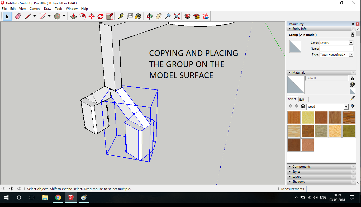
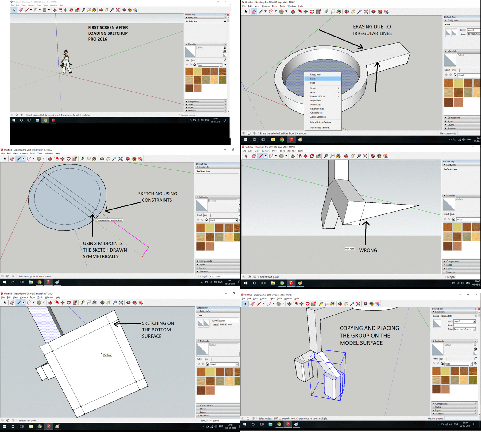
Following GIF illustrates the process in SketchUpPro 2017
The pros: Grouping command, rules, and arc command.
OpenScad is a parametric CAD which works on the basis of code . The code defining the solid needs to be written . Following ins the screenshot of the SCAD interface . As you can see from the screenshot on the left hand side of the screen is the code section and on the right hand side is the rendered output of the code . This is main basic interface for SCAD . Following file is used to generate a rack and a pinion . This file is editable .We can define the number of teeth on the gear as well as the number of teeth on the rack .
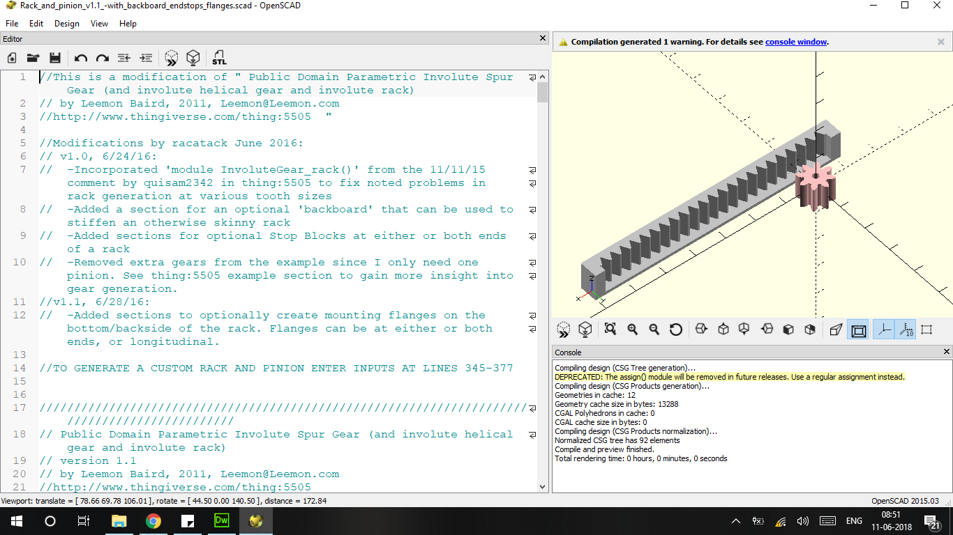
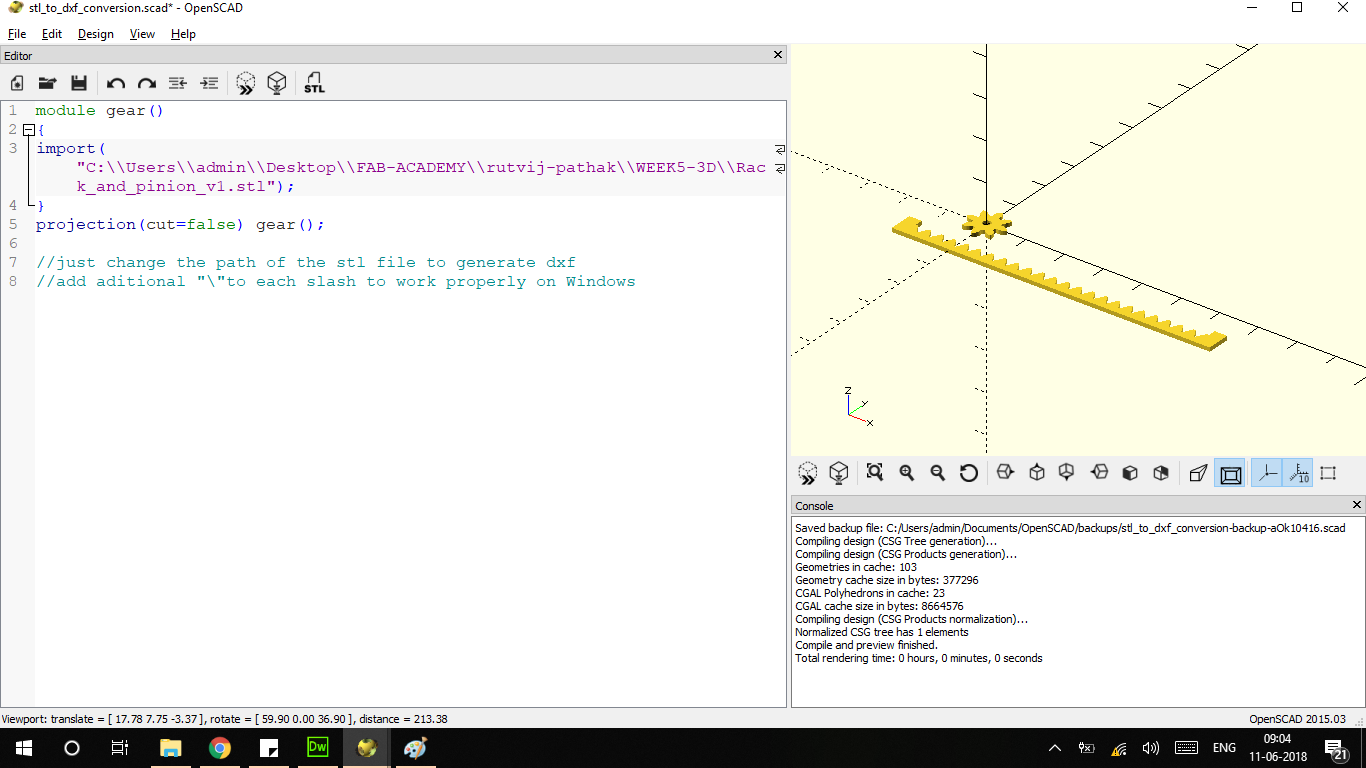
I could not directly use the stl file in Fusion360 as was generating multiple facets of the same surface . This lead to the idea of exporting dxf . This was not directly possible as there is no flat surface which was usable in this file. So somebody on the internet suggested cutting the stl in Scad to generate a dxf . THe image above imports the STL into the program and cuts it.
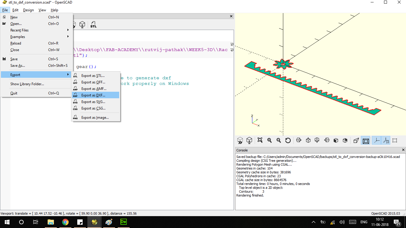
This is the screenshot after the program has been run . "Export to Dxf "option can be found under the file menu . It will output a DXF . This utilty is better and faster than the gear generating utility in Fusion 360. In Fusion 360 the module which generates the gear has fixed options where parameters are quite limited .
Fusion 360 is the main CAD package i am familiar with and have decent command over. I find the GUI of fusion 360 to be userfriendly and helpful hints next to commands make the program easy to use .
This is the timeline animation of the CAD design for my project . This is the animated timeline feature in FUSION 360 where the user can cycle through design as it was designed .This feature even allows you to jump at various sketches where you can edit the base features .
This is the joint which was constructed using the tools in FUSION 360.
This is the actual cutter joint animated . This is the actual cutter joint animated . This cutter joint is animated using 2types of joints . 1. Revolute Joints 2 . Rigid Joint . For this to happen one of the components needs to be "grounded" .
Simulation of the force applied to the rod to measure deflection . This is just a cursory force application as this force is the deflection which wull occur in when load is on the cantilever . That is when the person holding it has a cantilever .

Online client of FUSION 360 allows you to export the various types of 3d files . These files are useful for Unity .
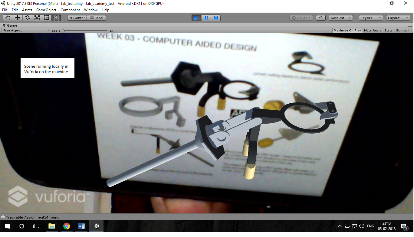
Unity and deep rabbit hole of discovery . I experimented with Unity by importing the models . The models that unity supports are “fbx ” and “obj” . Both of these file formats can be exported by the cloud client of Fusion360 . which makes the process extremely simply. I knew Augumented Reality after spending a few hour looking up at tutorials on Youtube about Vuforia I was able to get a basic AR setup natively running on the PC .
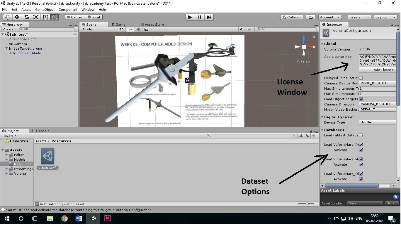
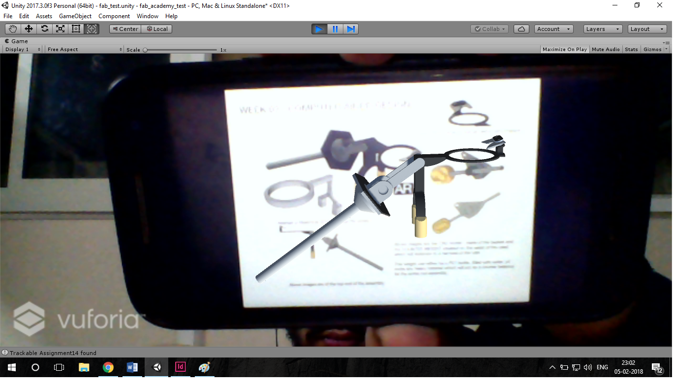
Unity imports the 3D file from any CAD data set . This is imported into as either an "obj " or "fbx" file these files can be scaled as any CAD program . The file on which the 3d object is to be projected is first uploaded on the vuforia website .This scanned image is converted into a target which is Vuforia compatible . THis is then imported into Unity where the 3d model is positioned on the target
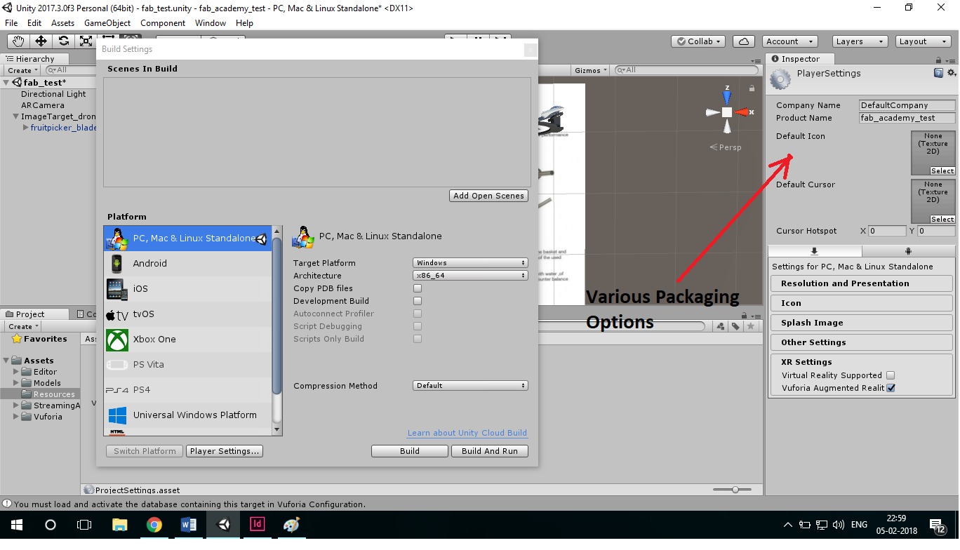
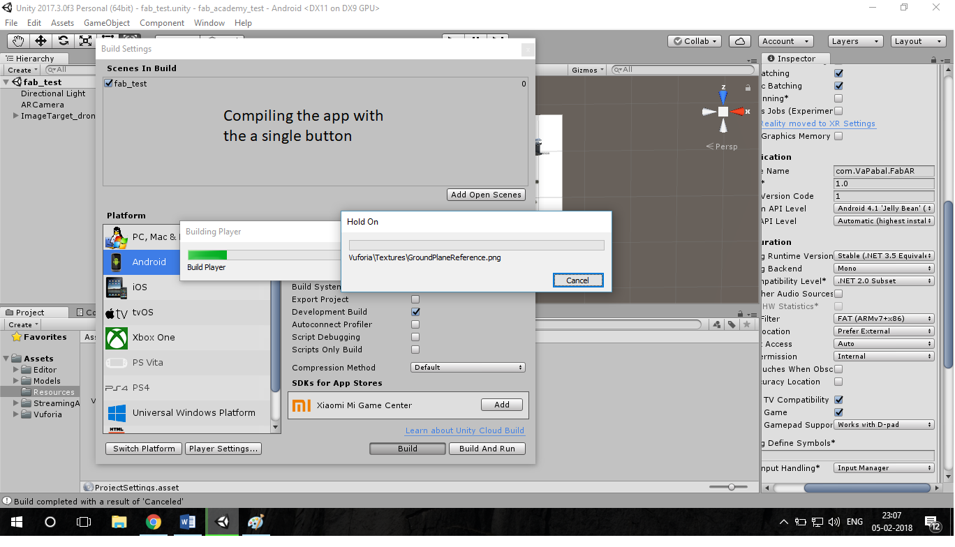
This is the packaging options available in Unity . Notice the support for Various platforms and packaging options . For Android Unity needs to be directed towards the Android SDK(Software Development Kit ) and the JAVA jdk (Java Development Kit )
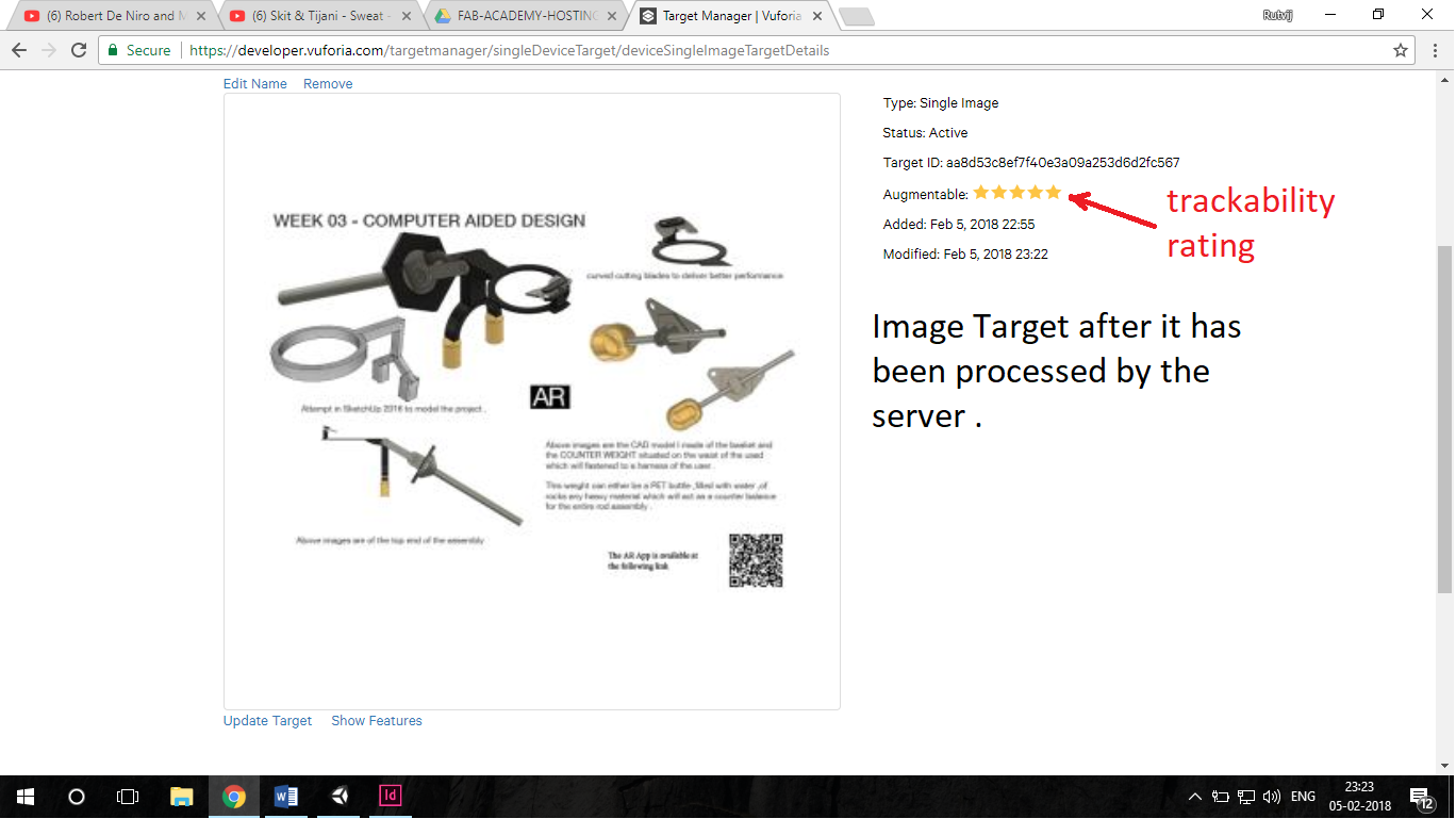
The image is given a trackability rating . This rating is based on the high contrast between the picture . In this case sharp contrast between 2 regions is appreciated rather than gradually changing gradient.
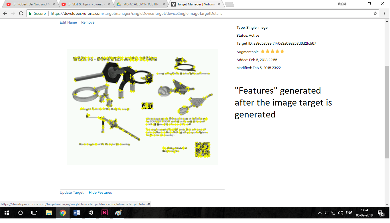
In this Image the features which are generated are shown . This features are the specific points which camera in the app picks up . So that when you move the camera around image in real life the camera doesnot lose tracking
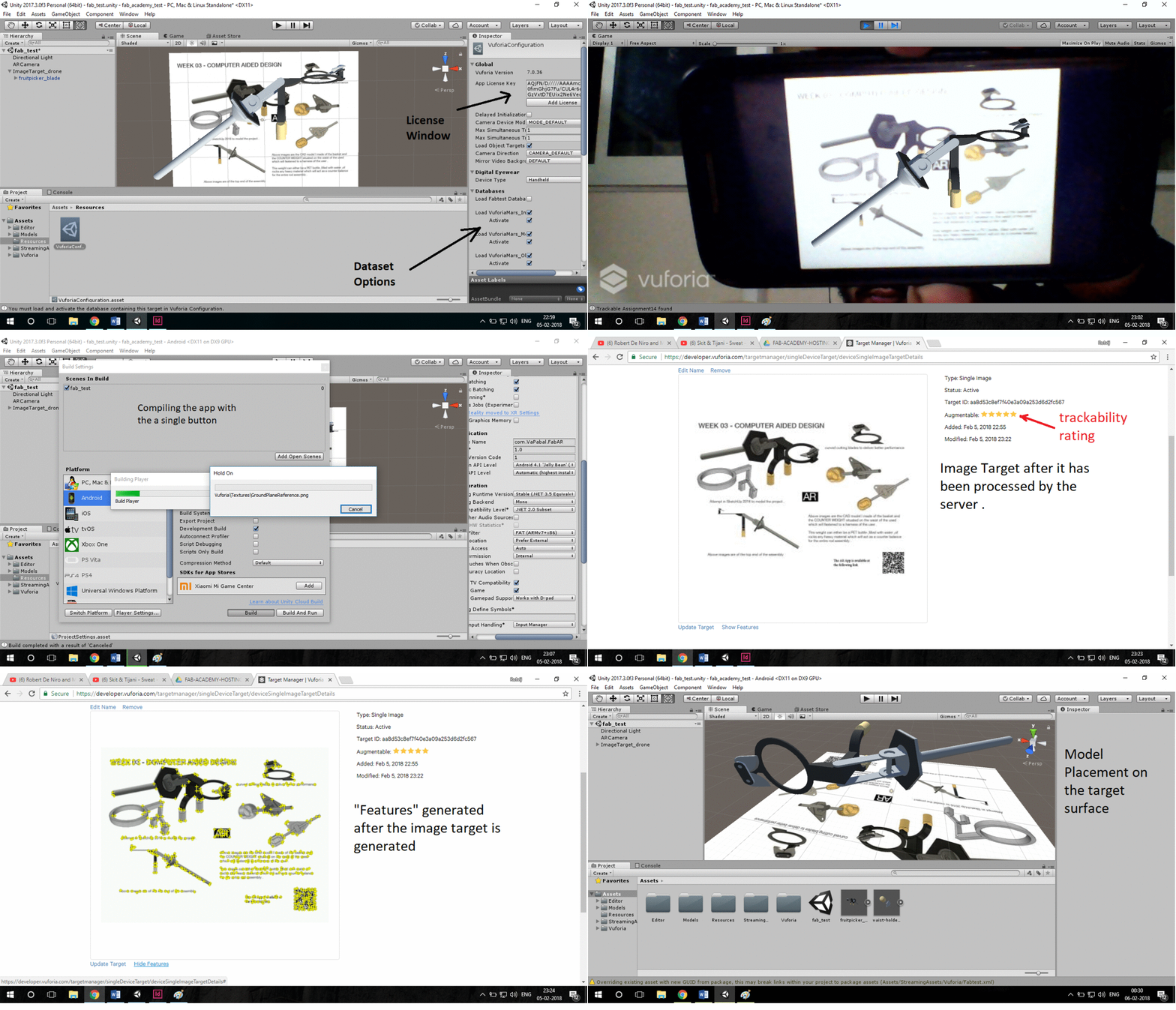
The GIF above shows the steps in using Vuforia and Unity.
One of the most comprehensive tutorials about Vuforia and Unity can be found here . https://library.vuforia.com/articles/Training/getting-started-with-vuforia-in-unity-2017-2-beta.html
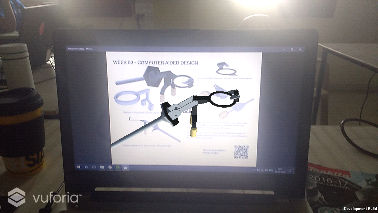
This is the screenshot of the AR App made in Unity . Link to down
Translated the sketch from a paper to SketchUp2016 .Used SKetchUp2016 to figure out that i had it strenghts such as ease of use but lacks the features of required for M-CAD . Learnt about SCAD , Fusion360 and SketchUp . Evaluated these softwares each of these softwares has his own merits . For eg. : Sketchup2016 is good for quick and dirty rendering a 2D sketch into 3D .