For previous year's FAB-ACADEMY Vigyan Ashram has made X-Y plotters . This year we decided to make something different . Thus the idea of the robotic arm was presented which was achievable and challenging enough to be done in 2 weeks.
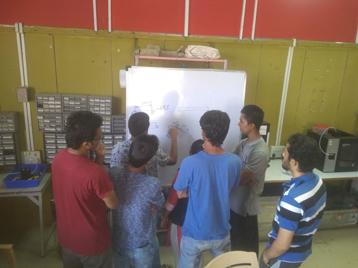
Initial team discussions
This week was mechanical design week . This week we 8 people at Vigyan Ashram decided to work together in one big group to "make " a robotic arm .
"Robotic Arm " is 3 axis robotic arm . There are 2 types of robotic arm which are usually used . The first type is the type where the joint has a motor inbuilt . The higher the number of motors higher the dexterity of the arm . THe most common type of robotic arm have 3 degrees of freedom. This has higher selfweight due to presence of motors at each joint . This increases the dexterity of the robot . The disadvantages of this arm . - Due to its higher selfweight higher torque stepper motors are required to hold up the arm itself .
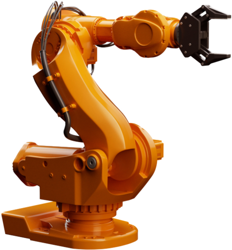
Types of the robotic arm
The second type of robotic arm is the parrallel mechanism arm . This 4 bar parralel mechanism has been used in famous robotic arms such as the MeArm and the uArm . Which are designed quite well . One of the advantages of this design that the motors are mounted at the base of the design . That lowers the center of gravity keeping the arm steady . This allows the torque to moderate for the same actuation force .
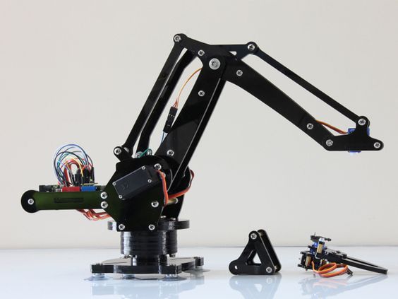
Parallel mechanism robotic arm that we selected
>This was a group assignment so we were eight members:1. ROHAN and CHAITANYA: Brain Storming and main Designing of the arm.
2. KAMALESH and KOMAL: Prototyping, Hands on skill.
3. ANAMUL AREFIN and RUTVIJ: Electronics and Interfacing.
4. SANKET(this is me!): Documentation, video.
5. UGYEN: End effector design.
After researching a spreadsheet was created which would be used by everbody to collect and pool the resources found on the internet .
In extended discussion , the team choose to go with option no 2 as the budget which was alloted by Mr. Yogesh Kulkarni was 3000 rs .(37 EUR ). Due to the remote location of Pabal . There is considerable lead time when getting components we decided to use the existing motors for this project .
This week we also made a MDF prototype to demonstrate the scale and reach of the arm .
Rohan Rege has worked on the 4 bar mechanism . on his webpage written here .
WEEK 16 - Machine Design
I worked on the electronics of the arm with Arefin .
My part of the assignment was to work on the electronics part of the arm
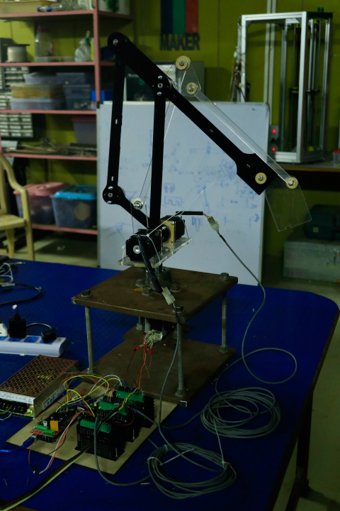
This is the final assembly of the robotic arm
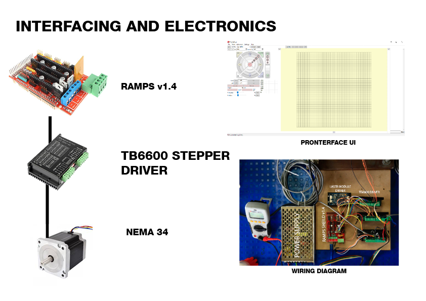
Arefin and I decided to use a RAMPS sheild with a stepper driver . This is one of the best and simplest way to use stepper motors . The firmware which was used to program the Arduino was Marlin . This is a python based GUI . We used Pronterface in Windows Build to interface it with our laptops .This is the interfacing diagram of the stepper motor driver . The TB6600 driver has been chosen due to its high current supplying capacity .The driver specifications can be found on this website : "https://www.dfrobot.com/wiki/index.php/TB6600_Stepper_Motor_Driver_SKU:_DRI0043s"
There was an attempt made by me to integrate these wires on the RAMPS shield by making a small pcb which will fit on the driver position of the RAMPS sheild . Following screenshots illustrate that process .As Ramps shield is an opensource design there is plenty of design resources which are available on the internet . I downloaded the RepRapjr library . This library contains all the electrical components for the RepRap.
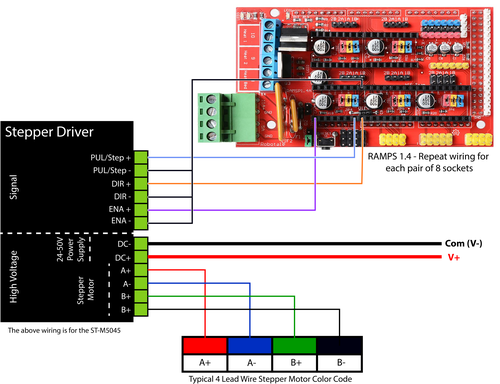
This was the connection diagram of the TB6600 with the RAMPS sheild which was to be managed and simplified using a breakout board
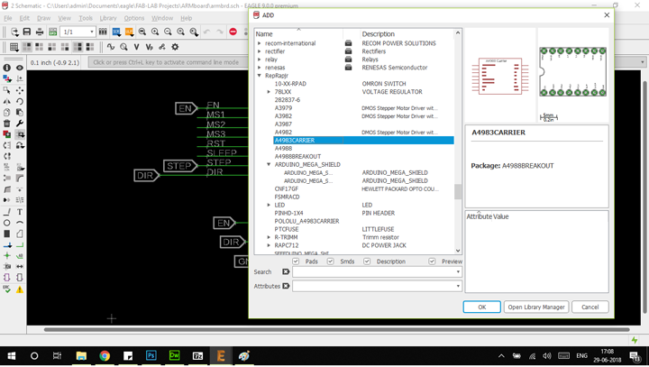
This is the eagle library of the A4988 stepper driver inside the RepRap library
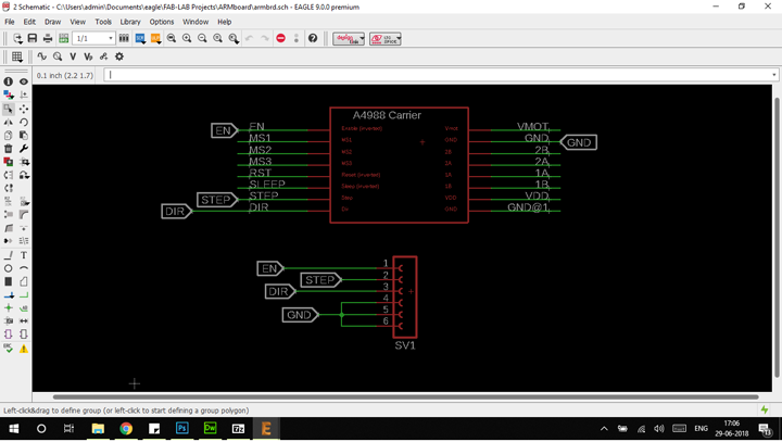
This is the schematic of the breakout board . which was created .
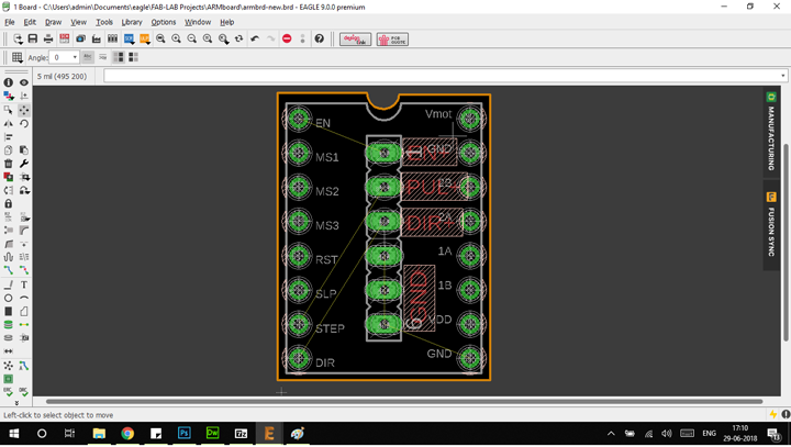
Placing the the female breakout header on the blank A4988 board .
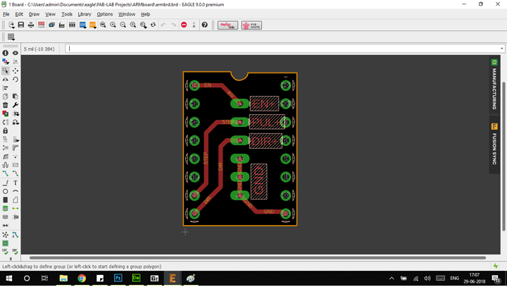
Routed A4988 board which will be placed.on the RAMPS board
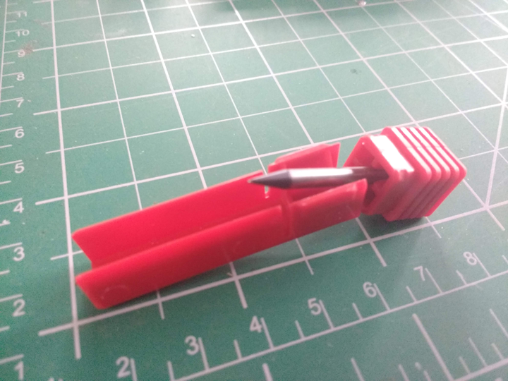
Disaster the bit broke due to powersupply glitches and the bit hitting the bed
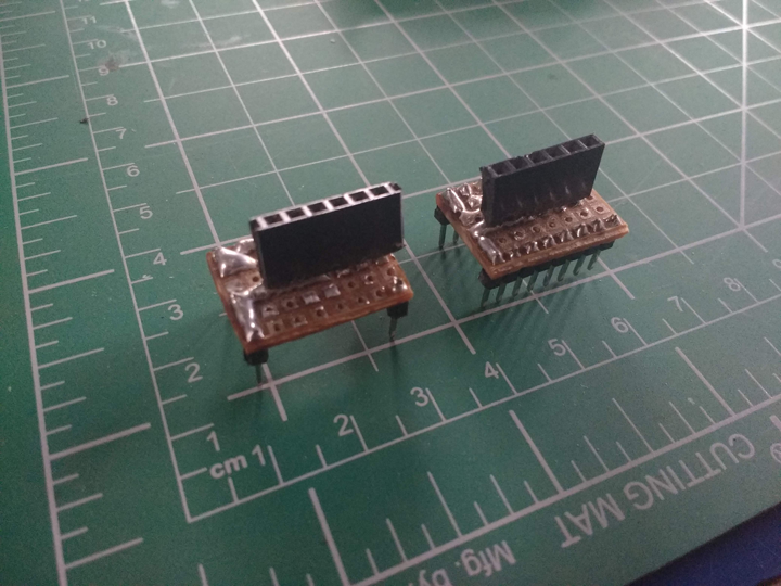
Quick and dirty solution was soldering the female header to a protoboard . for a quick solution to the time crunch of presenting the machine .
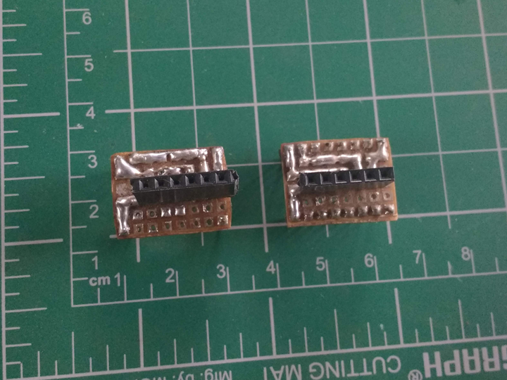
Top view of the board .
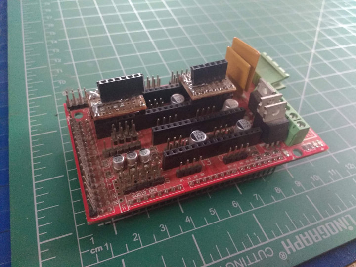
Putting the A4988 breakout board on the RAMPS sheild
I was also in charge of creating the document
Finally the arm is working and can be controlled
The main project page is linked here
The orignal files can be found here