This week we the assignmnent was networking 2 or more microprocessors. This week i used asynchronous communication for the communication . The difference between asychronous and synchronous communication , that in synchronous communication we need to use a common clock. In asynchronous communication there is a message format . Where there is always a start and stop message .
In telecommunications, asynchronous communication is transmission of data, generally without the use of an external clock signal, where data can be transmitted intermittently rather than in a steady stream.[1] Any timing required to recover data from the communication symbols is encoded within the symbols. The most significant aspect of asynchronous communications is that data is not transmitted at regular intervals, thus making possible variable bit rate, and that the transmitter and receiver clock generators do not have to be exactly synchronized all the time. In asynchronous transmission, data is sent one byte at a time and each byte is preceded by start bit and stop bit. - Source "Wikipedia"
Making flexible Circuits
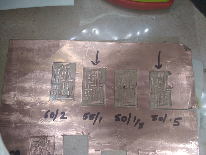
The above photograph is the force test of the vinyl cutter. I used a OHP sheet as the base . Put a thin double layer tape and on top a used a copper tape for the actual trace which are going to be cut .
This week we decided to use the Neils node board as a template for perfecting the flexible circuit boards. Above photographs shows that force and speed combinations we used to get the tracks cut perfectly and as cleanly as possible .
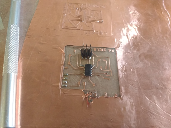
The above photograph shows solderability of copper. Testing the solder joints mechanical strenght. Solder adhesion test for the copper tape.
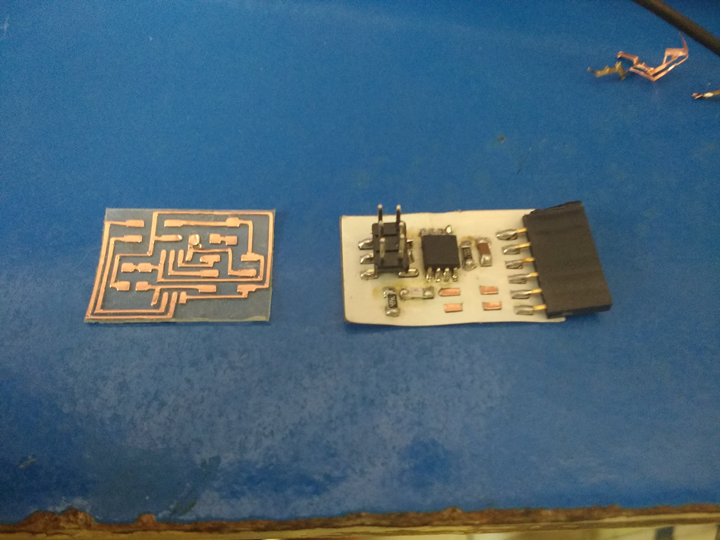
The above photograph is the final board made from OHP sheet + copper layer + white soldermask . This boards was made and flashed but the mechanical stresses from removing the female and male headers was enough to dislodge the copper traces from the botton OHP sheet .
Making the bridge board
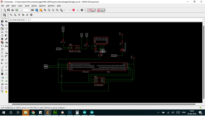
This is the schematic of the bridge board . Notice i have put an LED on PB0 .
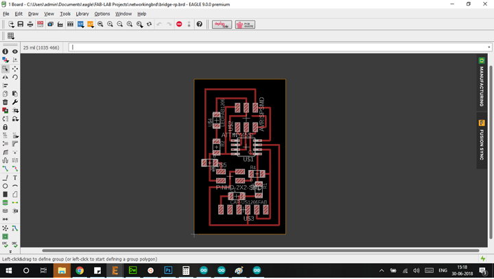
The above photograph is a the board that i have designed to be manufactured . This the briddge board . For the node I'm using the same board i used in the input devices week. which will act as a node board.
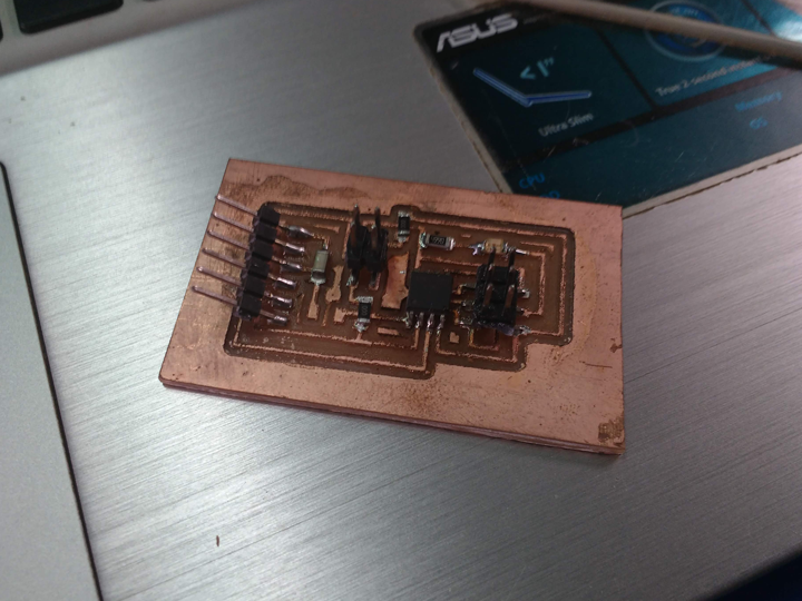
This is the bridge node in the network .

I will be using this bridge along with my final project board in tandem with the board which has been done in my input devices week.
Coding the bridge
The code first defines the RX and TX pins of the bridge as Attiny 45 has the USI which is Universal Serial Interface where you can define the RX and TX pins . To further aid this communication we need to call the SoftwareSerial library . In a one of the first declarations we define the RX and TX pins . We aslo define the node id for each indivisual board .
The next part of this code makes the microcontroller listen on the serial port on whether or not its id has been called . And when its called respond by blinking the LED .

This is the code which was used for the bridge . Chaitanya helped me with this code.

This is the serial communication port
This is the working of the bridge . The arduino is only being used for its RX and TX pins . A digit is sent to the bridge and the bridge is sending the same letter back . This shows the appropriate working and communication of the board . Notice at 13 second mark the bridge blinks twice after being called out on the serial monitor.
THis is the video which shows the entire networks responding to the commands being shown of the arduino . Notice the LEDs on the input devices week blinking after being called out on the serial monitor.