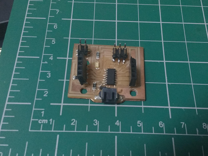
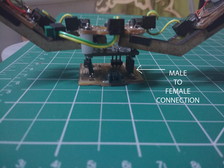
This week was input devices week . This week i decided to use the colour sensor TCS3200. I decided that keeping in line with the ideas for final project . I designed and execueted a stacked pcb design . The actual connection was implemented using male and female headers . The actual connection was done in the MCAD i.e Eagle . The total circuit was designed on a Attiny 44 . with the option of integrating it onto a network by using the RX and TX pins . for future system integration .
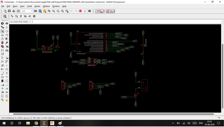
This is the schematic of the new project board .This contains a mosfet to control the high power LED's and a Colour Sensor name TCS3200.
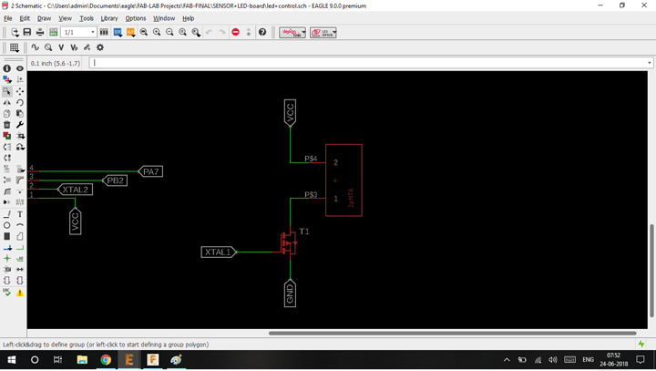
Notice i have used the 2 Pin MTA connector which is available in our Fablab. Following screenshots are series of steps taken to making your own eagle libraires . In the following screenshots below you will find 2pin , 3 pin and 4 pin connectors which have been done . In the files i have included the .lbr files for the same
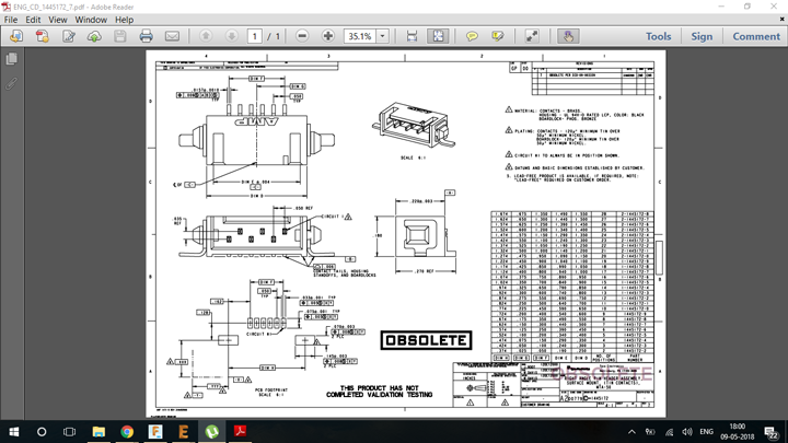
I first found out the part number of the connector . I emailed the company asking for the archived datasheet of the connector . They replied with the above datasheet which contains the mechanical details of the connector i.e pad dimentsions and distance between the pads. The was further processed into Fusion 360 .
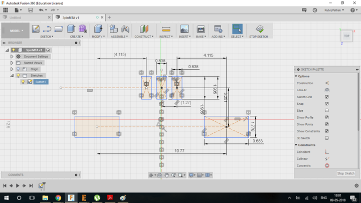
THis is the sketch i made of the connector in Fusion 360 according to the datasheet . The dimensions given in the dataheet were used as contraints .
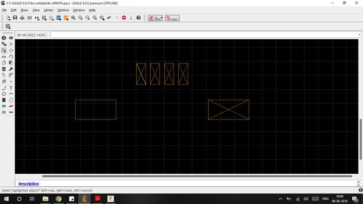
Importing the dxf of the connector into New >libraries > make package . This is dxf is imported into the layer "18 tPlaces ". This is one of the dxf import tests using a 4 pin connector . After this pads of standard sizes are put on the the rectangle .These are the pads which are linked in the schematic design of the new library environment.
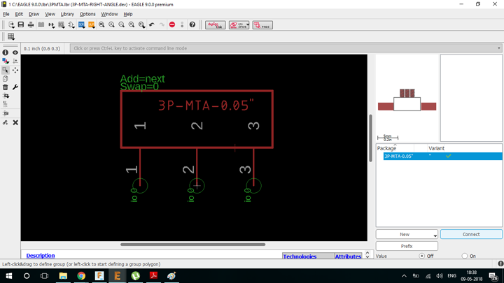
Following is the device maker in Eagle which links the physical package with its schematic counterpart . As highlighted "Connect" Button shows the actual linking portion. After this it can be directly saved as a DXF .
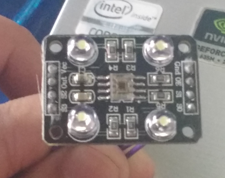
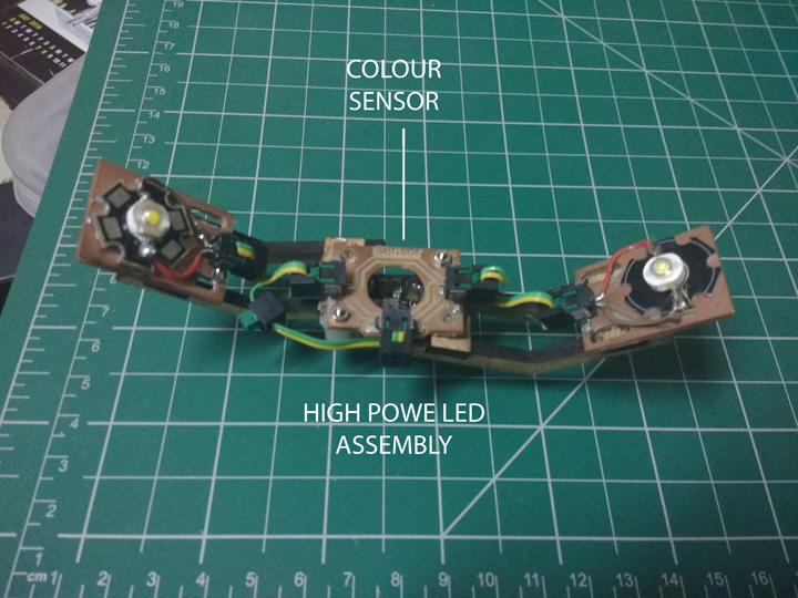
This is the colour sensor which called "TCS3200" I'm going to be using for interfacing this week . I measured the physical dimensions of the sensor along with the placement of the fenale headers . Which will help me make stackable pcb design . which will be helpful tighter integration of the overall project .
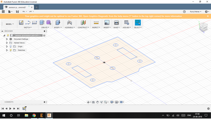
THis is the sketch which is used as the base of the dxf . I designed it in Fusion360 using basic sketch geometry. The position of the 2 female headers is critical . This is denoted in the sketch as the 2 rectangle boxes . The 4 mounting holes of the sensor have also been taken into account . To have mechanical
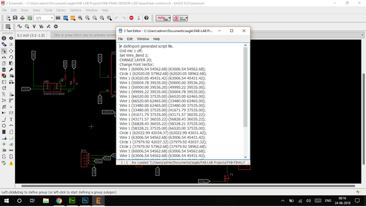
This is the dialog box which opens when a dxf file is imported into the design
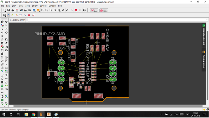
Placing the components within the contraints of the board
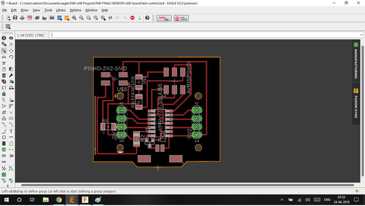
Final routing the board
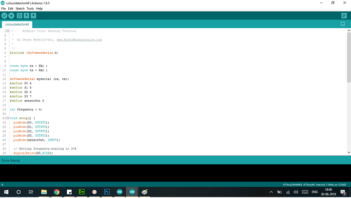
This is code for the colour sensor . The 8x8 sensor matrix of the colour sensor is switched ON and OFF one after the other to sample the same colour to different filters such as R , G and B . This is then frequency converted to obtain the numerical number of RGB . in the testing case i have used . a RED colored lid of a plastic container .
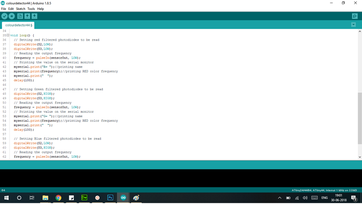
Notice the digitalWrite variations of (S2,S3) . This allows us to switch between various i.e 3 filters.
Personal Learning Milestones :
Learned about computer controlled machining . Learnt the importance of Speeds and feeds .The orignal files can be found here