This week we had group assignment, this may cause the same image to appear on pages of multiple students
We are using the old version of FAB modules. Although the newer mods are better, it takes more steps to accomplish the same task when compared with the older modules.
This week were tasked with:
1: Group assignment:
measure the power consumption of an output device.
2: Individual assignment:
add an output device to a micro controller board you've designed, and program it to do something
This week I attended a workshop on Drones at IIT Bombay. The workshop was conducted by the good people of Drona Aviation. The workshop lasted 2 days hence, I started working on this assignment on Monday.
This is a reason I am late for all the work. I'm trying to get up to speed with others.
This week the assignment was to add an output device to our micro controllers. Neil had a bunch of interesting examples, but I decided to hijack this week for the final project. Speaking of final project, my idea has been significantly matured from my early model. Each week after every assignment, I update/upgrade my project to and somehow try to use it. Now I can say that my current idea is more scientific.
For my project, I need to control LEds and Motor.
To save resources, I decided to make a daughter board for my my micro controller board I made last week.
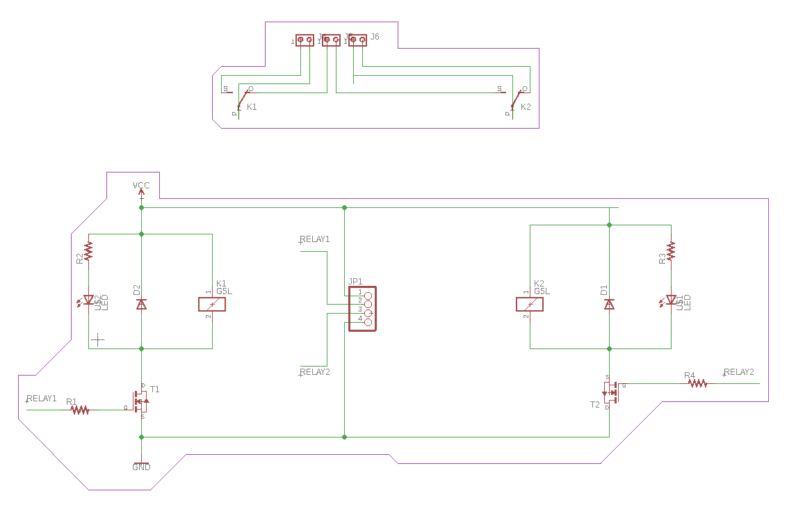
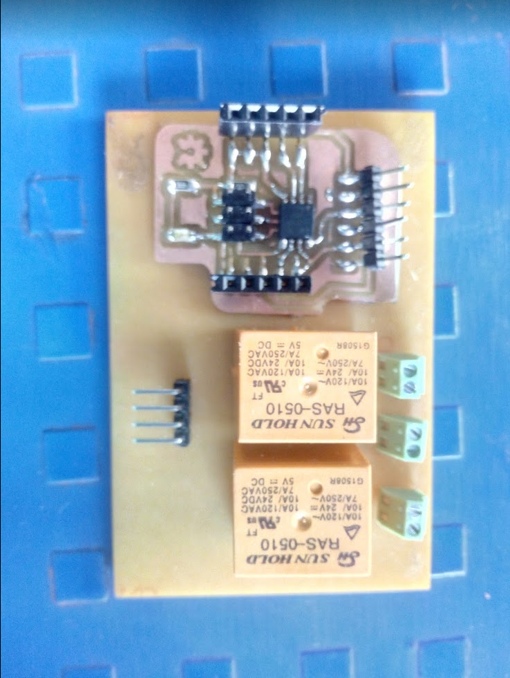
As for controlling LEDs and Motor, I was going to make a relay module. I was going to use a AC based LED strip and motor
After looking on the internet.
Designing the board was quite easy. I took help of our local instructor for the circuit diagram and for choosing the components from the right libraries, I was immensely helped by Komal Raut. Her secret, is to fall seven times and to get up eight times. And at the eight time helping me so I don't fall at all :).
Fitting all the components on the board is another challenge.
After a few trials and ~1hour later I was trim down my board
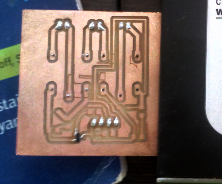
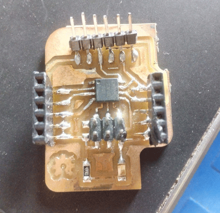
After milling, I started to solder the board together
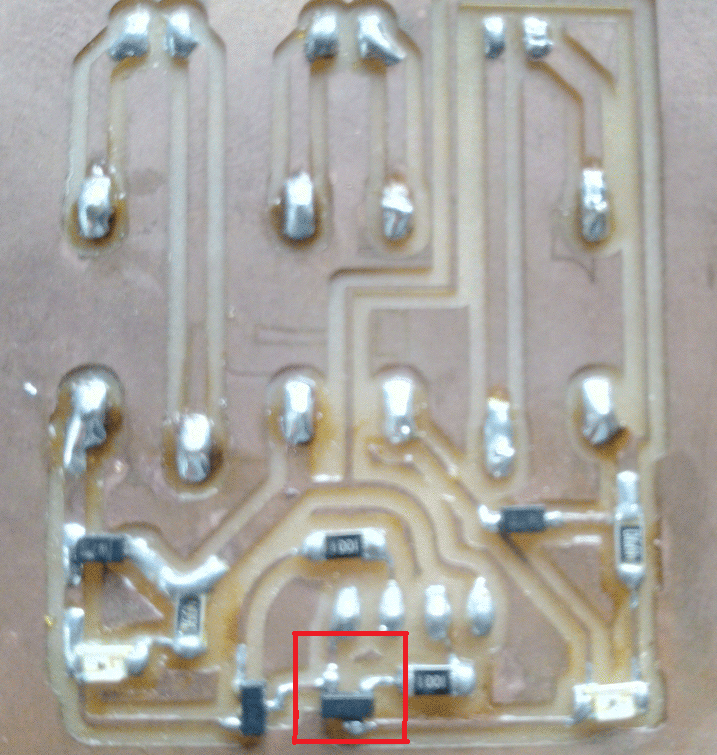
After soldering, I realized there is some error in my board.
I had connected the gate and source pins of the mosfet differently
This causes the circuit to fail.
Relays:
Relay acts an electrically operated switch. Relays are used where it is necessary to control a circuit by a separate low-power signal, or where several circuits must be controlled by one signal. Small micro controllers like those in the attiny family do not operate at high voltage and high current. Hence we need to use relays for switching purposes.
A relay has 5 terminals:
1: NC - Normally Connected
2: NO - Normally Open
3: Coil - Coil of the relay (2x)
4: Com - Common port (GND)
As the name suggests the ports NC and COM are connected be default (left)
If supply is provided to the Coil, the NC is disconnected and NO is connected (right)
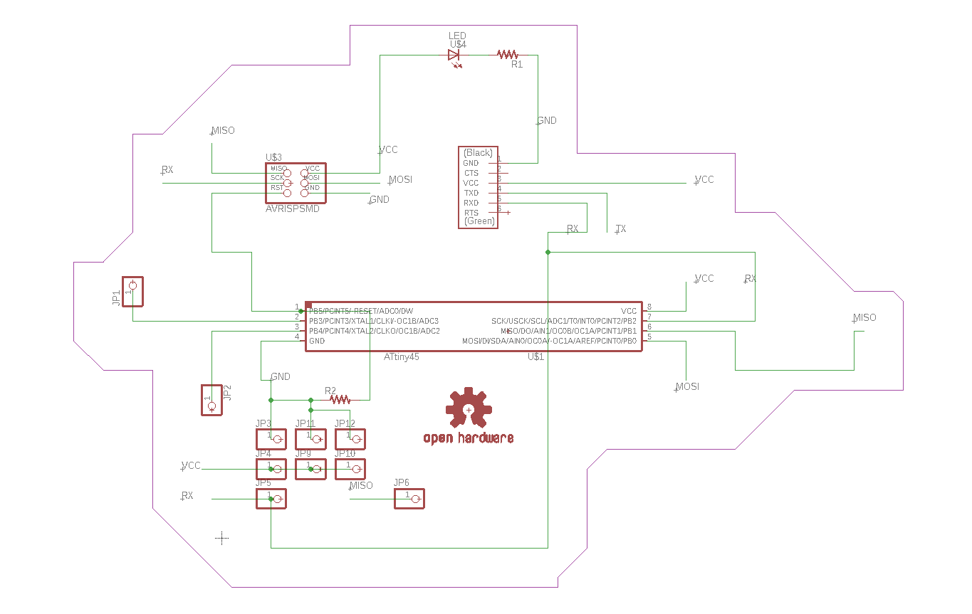
For my main board I decided to go with an Attiny 45. I did a simple board with FTDI, ISCP ,3 +Vcc and 3 GND, and headers for PB3 & 4.
The this board board file is available here and the schematic file here.
The traces of the are also the same. The only thing is I did not remill the sensor part.
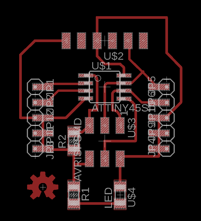
Traces:
Cutout:
For programming, I'm using Arduino as ISP.
I have used this set this up earlier here
I'm following the guide by reading here.
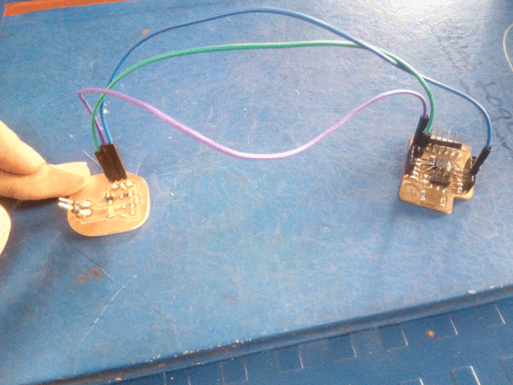
The Uno has the ISP sketch loaded from the examples directory and that works- the heartbeat LED pulses nicely. On the hardware side I have the ATTINY (surface-mount), soldered to my board with all its pins verified-soldered with a voltmeter. I use a header-pin strip, held by hand to get the pins touching the surfboard, to get the signals from the Uno to the ATTINY.
But while burning,
        avrdude: Device signature = 0x000000

        avrdude: Yikes!  Invalid device signature.

        Double check connections and try again, or use -F to override this check.
but sometimes the number is ff0000 or ffff00 or ffffff
I'm currently stuck here, a bit of googling reveals that this caused due to poor contact between the programmer (Uno) and the ATTINY pins.
My instructor helped me by resoldering some pins for me. This also had no effect. I plan to try again with a completely new board later.
I after some trial and errors I was able to get the boards working, it was faulty jumper cables.
My instructor helped me with setting up the burning.
Now that my board was done it was time to add my output device.
for my project I'm using a motor so I decided to try to run a motor.
Due to problems with my first board, I decided to make a simple MOSFET board.My instructor told me to use to MOSFET as switch.
The sketch for motor is similar to that of the blink as I was going to use a relay but since the motor is of only of low voltage.
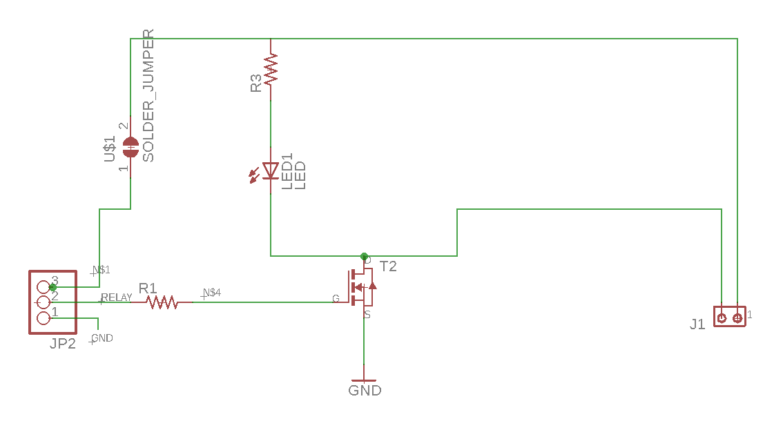
I'm using a P-channel mosfet, So the circuit I made is as follows;
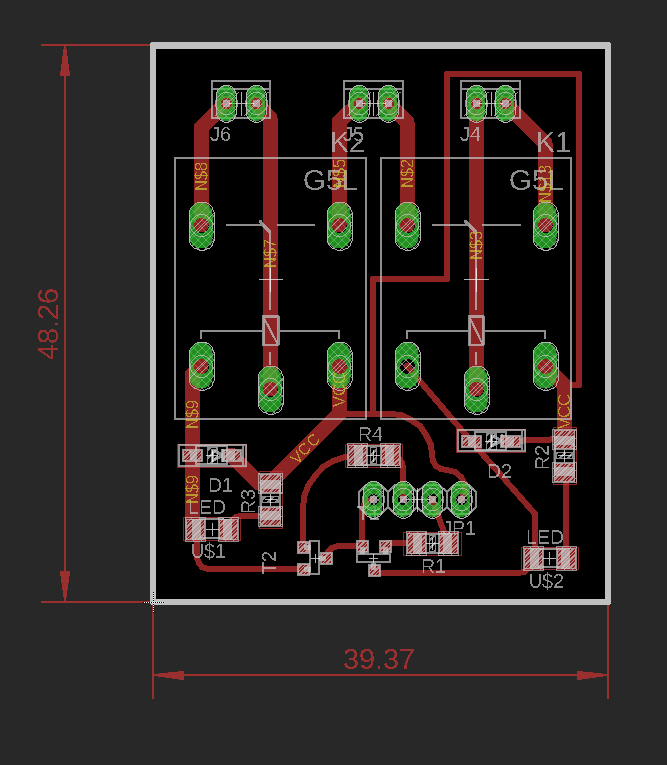
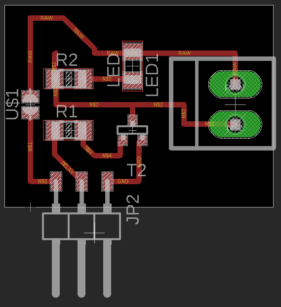
After spending sometime I was able to successfully route it as follows:
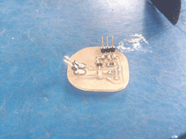
After soldering it looks like this:
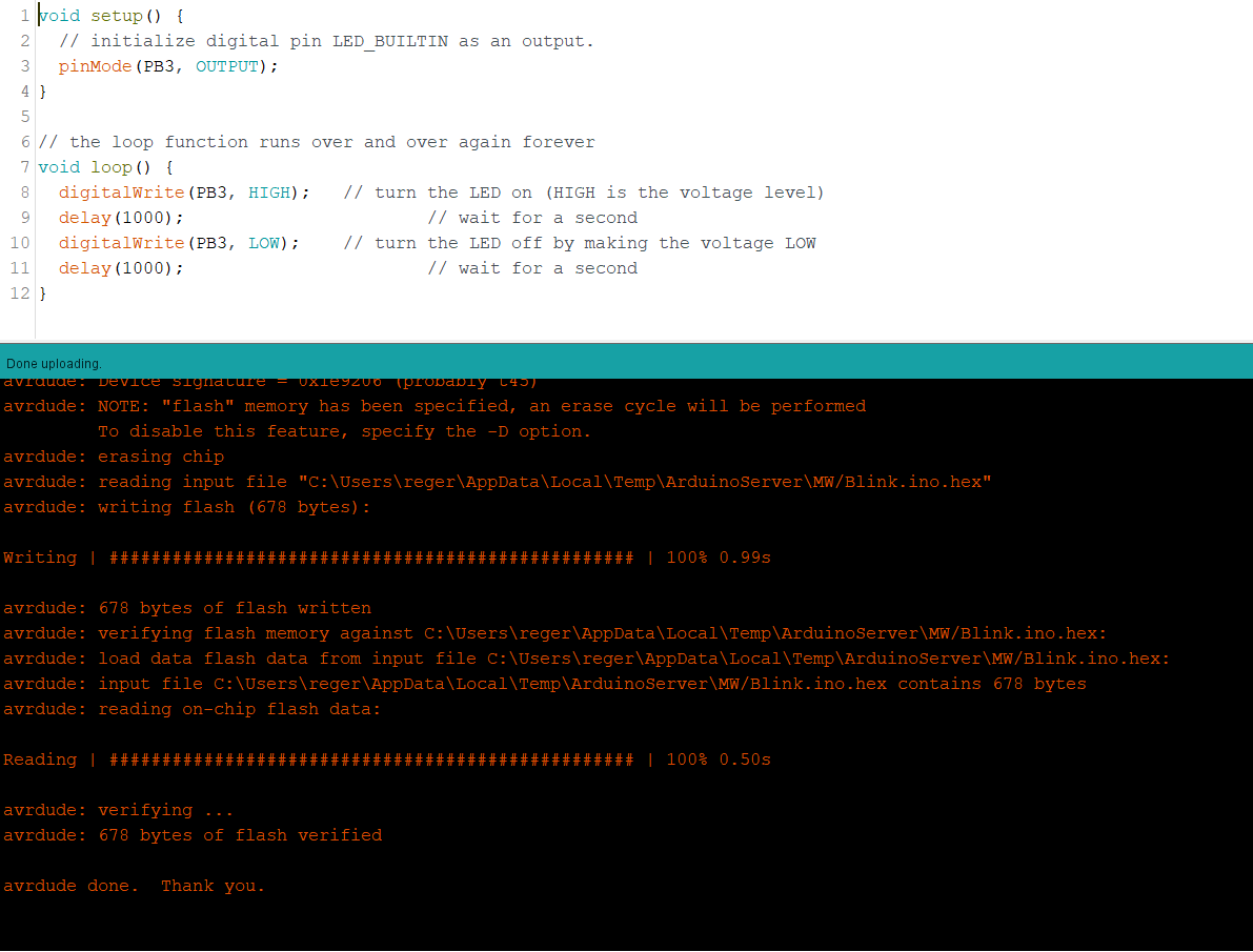
My code for switching is based on the blink program of arduino.
It can be found here.
The code is quite straight forward, I have defined the pins with output in the void setup()
Then I want the motors to turn ON and OFF regularly for ever,
For such things I normally use the void loop()
Hence I've used a simple delay program to control it
For programming I've used the Arduino IDE. I have followed same steps as i followed before, which are available here
And added the mosfet in between the motor and GND.
Group Assignment:
For group assignment, we were supposed to measure the power consumption of the output device.
We had 12V DC pump, 5V DC motor
We calculated the power consumption of these as follows:
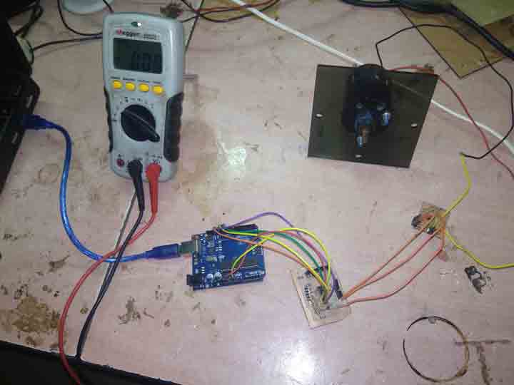
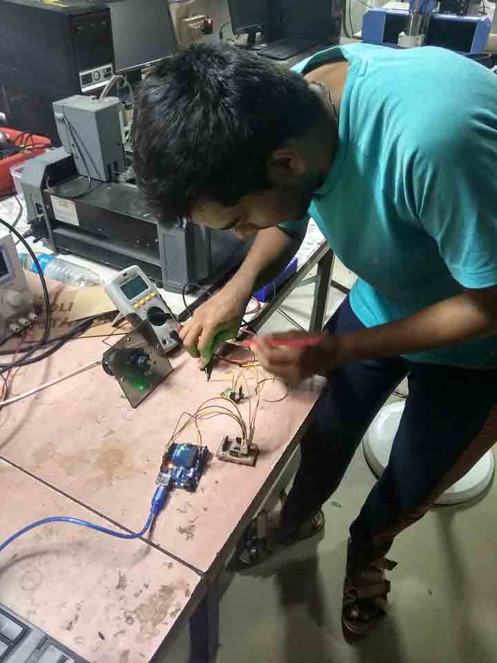
1: 5V DC motor
For this we setup the connections directly and powered the motor through the board..
We had o
Tne board with P channel MOSFET, rated load of 5V.
The formula for calculating power is P = V * I
Where:
P = Power
I = Current
V = Voltage
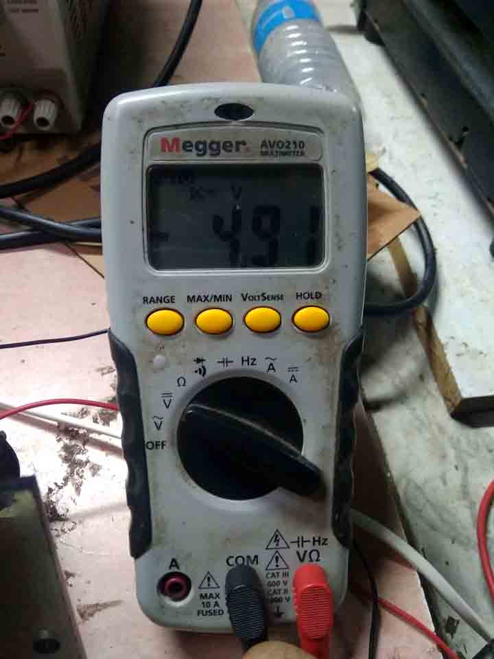
To calculate the voltage, we connect the multimeter in parallel to the circuit
The value of voltage is
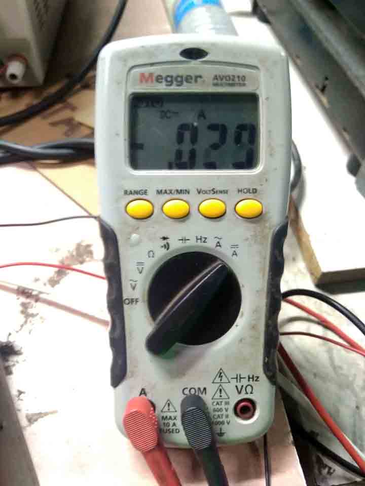
To calculate the current, we connect the multimeter in serial, Many multimeters have different ports for measuring current and voltage
The current is
Hence the total power is 1.432W.
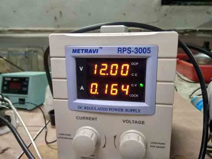
2: 12V DC Pump
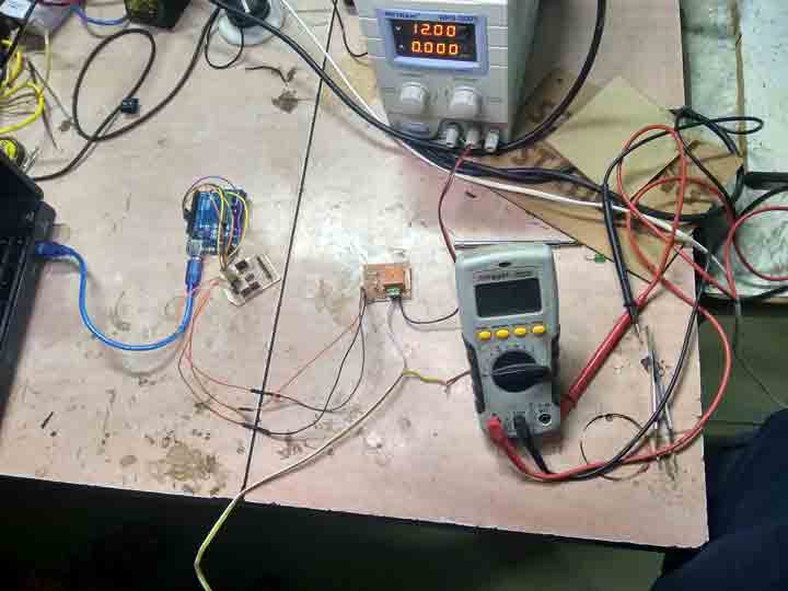
This was relatively easy, I connected the relay in between the ground of the DC power supply and the water pump.
In DC supply I set the max voltage to 12 V and max allowable current to 2amps.
Then I turned on the setup
The values of max current and voltage appear on the screen of the DC power supply
As you can see the voltage here is 12V and current is 0.164amps
So the total power consumption is 1.968W