1: write an application that interfaces with an input &/or output device that you made, comparing as many tool options as possible
Group Assignment:
For group assignment we decided to try as many interfacing softwares as possible.
MIT APP inventor
Mit app inventor is has block like UI. I personally hate this UI, I prefer regular text based interfaces then later GUIs
The app inventor feels like a balant rip off of the old Scratch UI.
Like all button/drag to drop based UI, the app inventor also suffers same fate.
It is very easy for simple tasks, but the work keep son getting complex, it becomes cumbersome to use the GUI to pick stuff
Arrange it.
and then place it
Hence I did not programmed/interfaced my board in MIT app inventor
Pros
Easy to use for beginners.
Kids will looooooove it!
Supports live testing by connecting the Phone/Tablets
Cloud based, hence no need to download and install program, can work from anywhere on anything.
Processing
Processing has the same UI as Arduino IDE., Magic of opensource softwares.
Both the processing and Arduino IDE feel as a package.
In technical side, Processing is also an editor like the arduino IDE, but it supports java (and other languages via addons).
I've used processing before a little bit
It basically receives and/or sends all data via the serial Port.
We can then manipulate the data as we like.
Like MIT app inventor, this also feel a little childish.
Pros
Easy to use for someone who has used JAVA before.
Due to its opensource nature, very versatile, i.e. can be used with other languages too.
Lots of example code available, to work with and also good community support.
MATLAB
I had only heard about matlab in college, but never used it before.
In my initial impressions I liked it.
The way matlab controls your PCB is very different.
I planned to use this for my individual assignment. Pros
Commercial software (bad), but almost all schools and universities have it.
The largest community support
Compatible with Octave (Opensource equivalent)
Individual Assignment
For this week, I decided to use Matlab for interfacing.
I did a program with MATLAB GuiDE to turn on and off the led.
To do this I used arduino Uno.
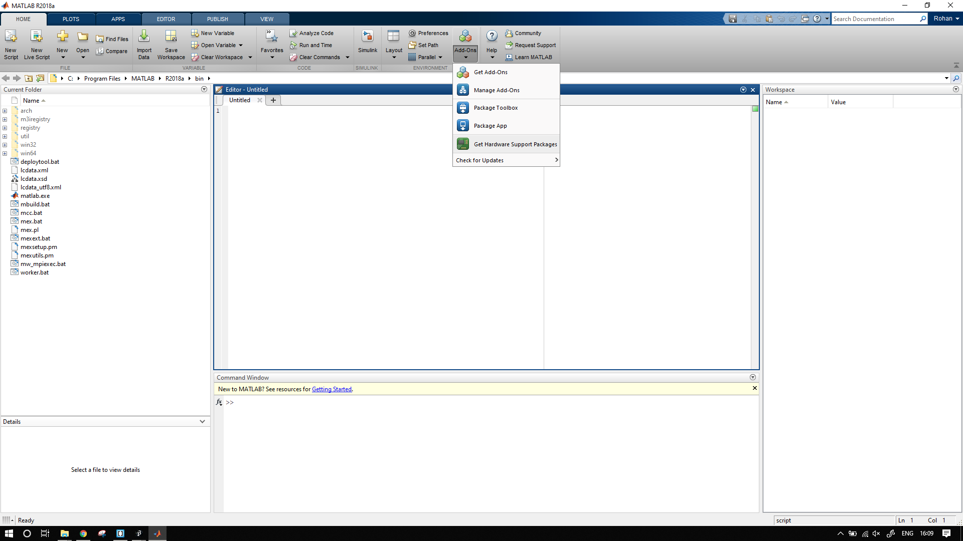
We need to set up matlab environment for using arduino hardware.
To do this, add the click on add-ons
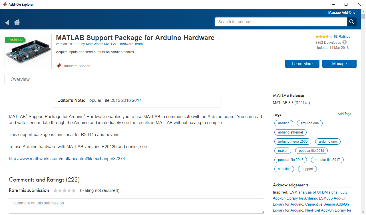
Then search for arduino hardware for matlab, and install it.
Install the MATLAB support files not the Simulink files.
After installing this will setup the arduino to work with matlab.
To test successful install remove the arduino and reconnect again.
The Command Window should display something like this.
Note: I have installed both the simulink as well as matlab libraries hence I get the second line of code too.
If you have installed only simulink you will get only the first line.
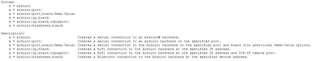
to setup arduino we need to assign it to variable.
To do this we use the following commands
a = arduino(port,board);
Is generally used if the board is arduino-like or a clone of arduino to specify the ports to the matlab.
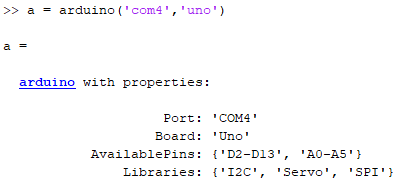
In my case it is a = arduino('com4','uno')
the output of this command is as follows
In matlab the arduino pins are classified into two types analog and digital pins.
Digital pins 0-13 are named as D0-D13, while the analog pins are named as they are A0-A5
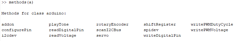
To see in brief the commands available we use the methods command
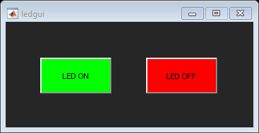
For testing I used simple LED ON/OFF switch.
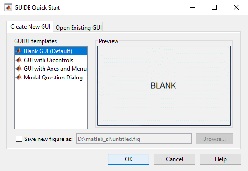
To start with GUI I used the matlab guide command.
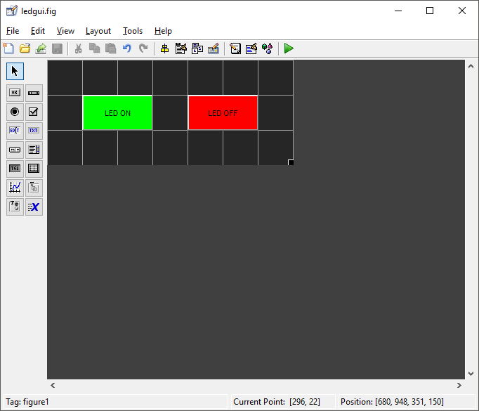
Create a blank GUI, the add two buttons
Modify the text (String) on both the buttons and also change the tag (changing the tag name is not necessary)
Now save the GUI. Matlab automatically generates the a code.
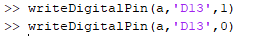
Before we edit/modify that let us look us look at the code to blink and LED.
Using the writeDigitalPin we can blink the led from command window as follows
My program for LED blinking is available here
WE need to add the same code to in the GUI but it should be controlled by buttons rather than the for loop.
My code is available here
I had made a board for LM35 temperature sensor.
I decided to make a similar user interface for it.
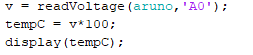
In data sheet we can see that the output voltage is 10mv per degree rise in temperature.
So I decided to use the analog inputs to determine the voltage given by LM35.
The basic program to read the temperature is given by
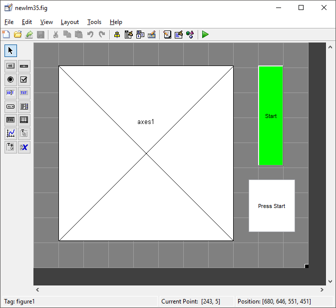
I decided to plot a simple graph of the calculated temperature.
Again I decided to use the matlab GuiDE.
I used
1: Push Button
2: Graph
3: Text Field
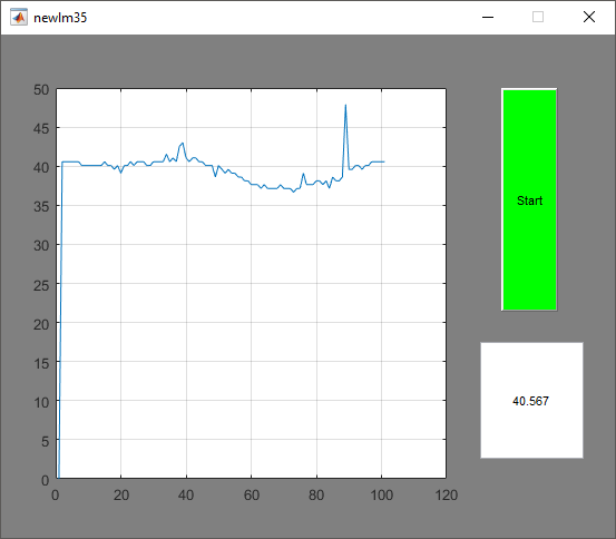
I plan to use a for loop and take 100 readings.
My complete code is available here
The average temperature today is 40 centigrade. !!!