Rohan Rege
Fab Lab Zero
Vigyan Ashram
<- Home
This week we had group assignment, this may cause the same image to appear on pages of multiple students
This week were tasked with:
1: Group assignment:
test runout, alignment, speeds, feeds, and toolpaths for your machine
2: Individual assignment:
Make something big.
Group Assignment:
For Group assignment we discussed wth Mr. Anasane from COEP.
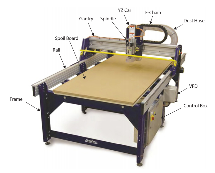
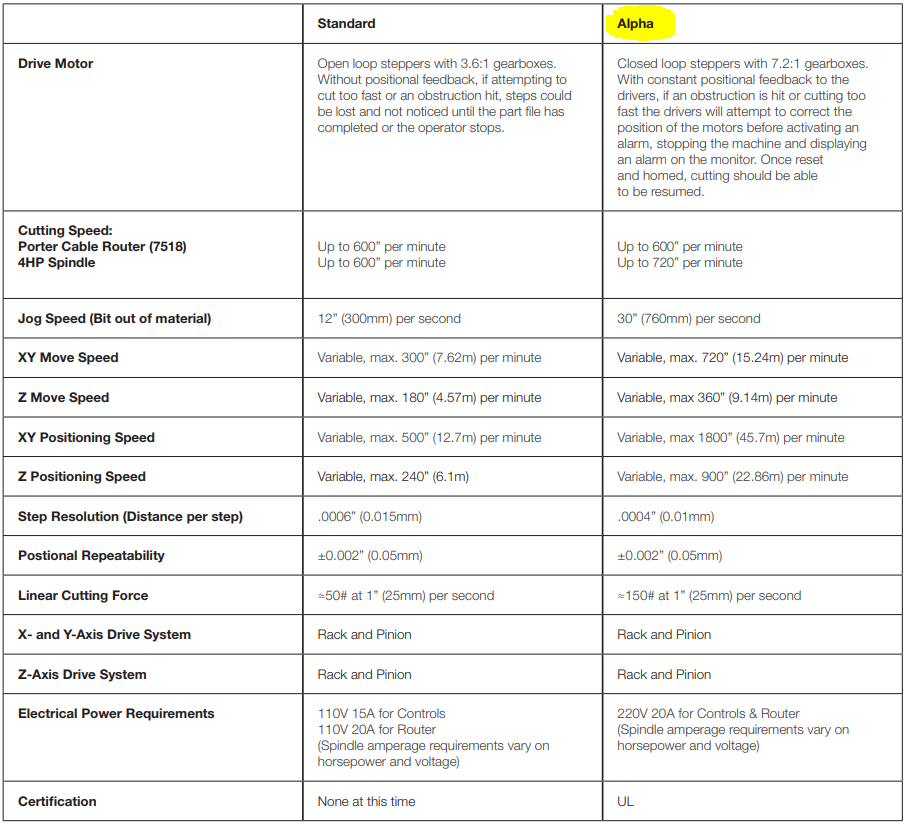
The basic specs of Shopbot PRSalpha are as follows
We discussed with the main problems and downsides of using shop in asia, specially in India.
Shopbot seems to have poor reputation for service.
He explained us few thing about CNC milling.
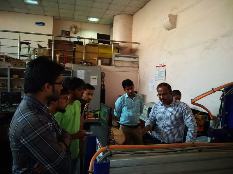
For group assignment, we were given a lecture by Mr. Anasane of COEP.
Seen below..
Administration of coep was very adamant, and did not allow us to test the specs to the limit.
They valid reason, if the shopbot failed, the service is very costly and it takes almost 3-4 months to get it repaired.
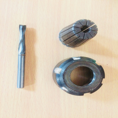
We also learned how to change the milling end of the shopbot.
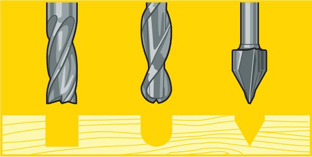
Milling bits play an important part in the milling process.
- Ball nose mills produce a rounded pass and are ideal for 3D contour work, because their rounded edge reduces jagged steps when cutting several stepped layers. Ball nose mills can also be used to cut wide paths with rounded edges by reducing the step over amount (overlapping distance between) between passes
- Fish Tail cutters are used to produce a flat surface.
- Straight bits are made to skim the surface and leave a smooth flat finish
The next thing plays an important role is the Feed rate, Stepover, Plunge rate and Spindle speed.
- Spindle Speed - rotational speed of the cutting tool in revolutions per min
- Feed Rate - Surface speed at the center of the rotating tool
- Plunge rate - It is also known as stepdown, it is the distance in the z direction per pass that a cutting tool is plunged into the material
- Step Over - the maximum distance in the x/y direction that a cutting tool will engage with uncut material
The formula for calculating feed rate is,
ChipLoad x CutterDiameter x NumberOfFlutes x SpindleSpeed = FeedRate
Where:
- Chipload is the amount of material cut per tooth (feed per tooth)
- Number of flutes and cutter diameter are determined by your tool
- Cutter diameter is the diameter of the tool
Depending on the size of your bit, the chipload for plywood is between 0.005 inches 0.01 inches per tooth. For small bits below 1/8 inch start with 0.005 and increase from it there. For bits 1/4 inch and larger you will probably not break anything starting out at 0.01.

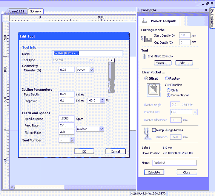
The settings for the tool used by us in Shopbot are as follows:
- Tool Diameter: 0.25in
- Pass Depth: 0.27in
- Stepover: 0.1in (40%)
- Spindle Speed: 12000 r.p.m
- Feed Rate: 27mm/s
- Plunge Rate: 3.0mm/s
For wood, general rule of thumb is to always make pass depth 1/2 the diameter of the tool. So in this case of a 0.25″ (1/4″) end mill, The pass depth should be to 0.125″ (1/8″). Depending on the wood you are cutting, you might be able to increase this. Pine, for example, cuts well at 0.25″ (1/4″) deep whereas Oak works well at 0.125″ (1/8″).
NOTE: As a general rule, One should not exceed the diameter of the tool as it can put undo stress on the machine, spindle and the tool. The only exceptions to this would be for very light material like foam or Balsa wood.
We know this, still you can see that the Pass depth is more than the tool diameter, We tried to convince the administration at COEP, but they were adamant on their parameters.
Being their machine, we had to use these values.
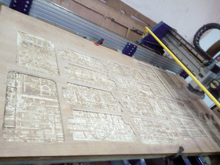
To test the characteristics of the machine, we made a few test parts.
Then we varied the parameters of the cut for each of the part.
Sadly we were not allowed to vary anything other than the RPM of the machine.
The COEP recommended RPM is 12000, they did not allow us to go above that speed.
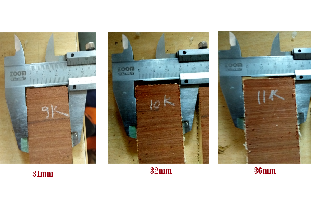
We cut parts ranging from 9000rpm to 12000rpm and pocket of 10K and 12K.
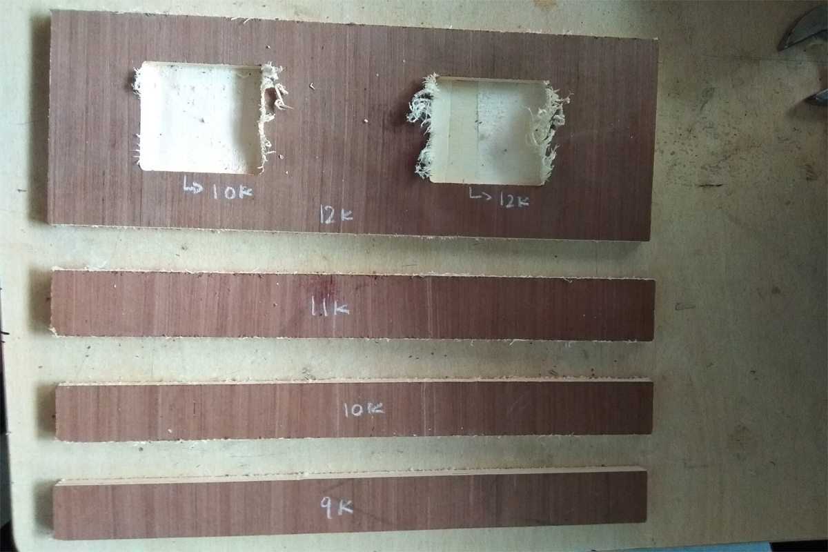
Upon closer inspection, we find that the recommended 12000rpm is the closet to the designed value(35mm). He decided to use this for all further cuts.
Also, same thing for pocket,
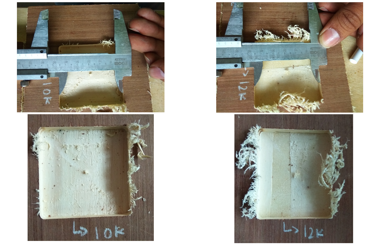
As you can see we have some kerf, I need to keep in mind while cutting our design
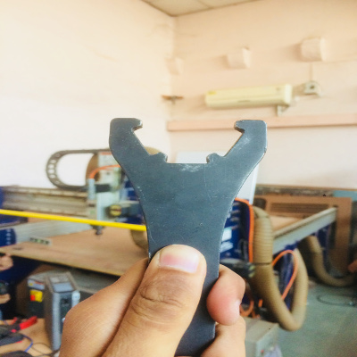
We also learned how to change the milling bit.
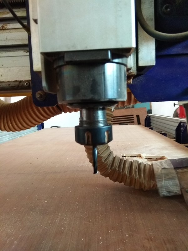
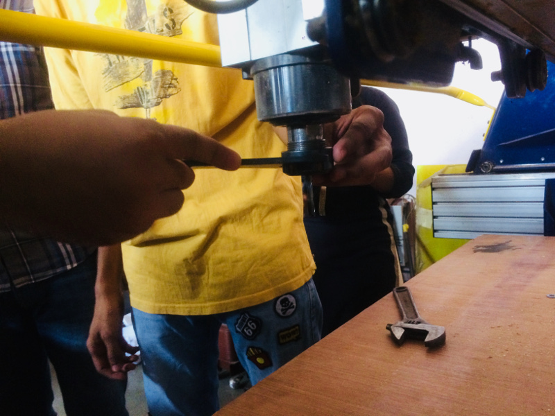
Shopbot provides a special tool to remove the milling bit.
Ordinary spanners dont work as expected.
Apart from the type of bit there are other important parameters that need to to be specified while milling.
These parameters vary machine to machine and bit to bit also depend upon the material used.
Individual Assignment
The assignment sounded very simple, "make something big"
This is make us familiar with large format machining. theoretically we change from 3mm to 3feet. :P
Upon closer inspection, this wholly different. This is basically a whole new ballgame.
In vigyan ashram, for larger format machining, we have only one larger cnc machine, a Plasma Cutter. It is a locally assembled machine. The bed size is 4 ft by 6ft. It is basically a 2 axis (X-Y) router with plasma torch attached to it. There is also availability of option to replace the plasma head with gas torch.
In my experience, the accuracy of plasma is not very average.
Like all C/NC machines the plasma cutter requires DXF files. There is propriety software which then converts the DXF path into Gcode. This can then be fed into the machine.
The machine of choice for this assignment is shopbot.
Vigyan Asram does not have a shop bot or any wood cutting CNC machine. But a similar machine is present with COEP Fablab. We were allowed to work on that machine for this assignment.
As the name suggests quite simply, "make something big", but what! that was my question.When someone says make something big, this comes to my mind
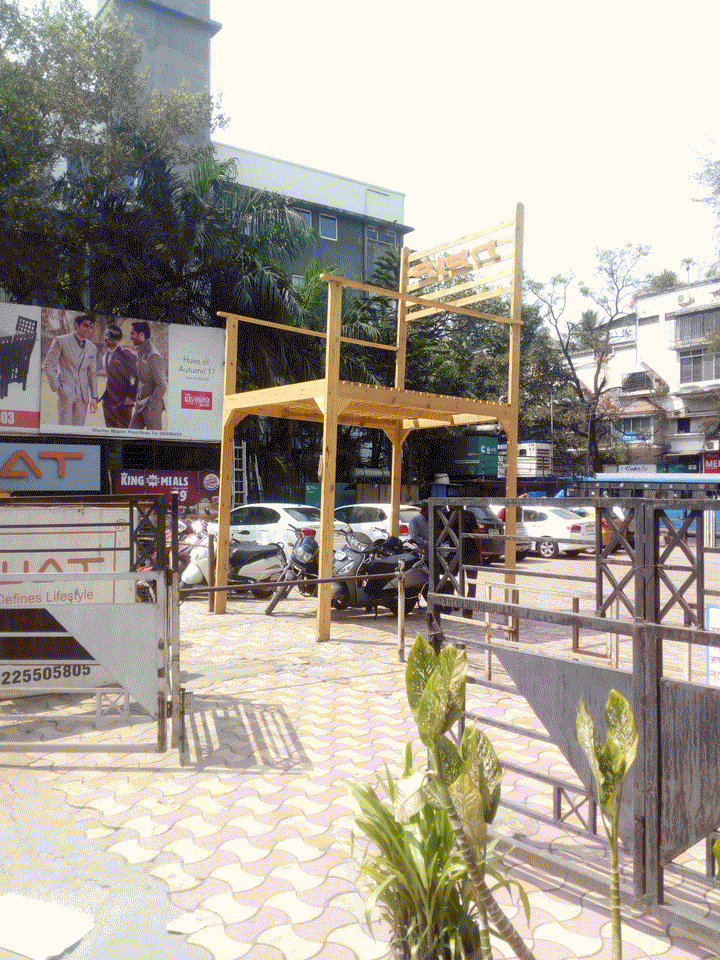
The above image is from a local furniture shop from pune.
Now that is something big, good for advertising, but feels useless. I wanted to make something useful. There in I had an idea. In Vigyan Ashram we have a DIC: Design Innovation Centre. In DIC, many times I have to work in machine shop to 'machine' components. While working in workshop I noticed a few things. There is no place to sit (other than the floor) the bench for bench vices is not perfect.
My plan is to make a table for bench to mount bench vices and a couple of stools for sitting in the workshop. I wanted to use/implement the the press fit joints I learned in previous assignment. I wanted my 'makes' to be entirely made without fasteners.
After a few hours on design, I decided going against making a table. Bench vises require a very stable platform. Also they should not move while machining. It will be hard to achieve with only press fit joints.
Hence I decided to go with making a few stools
For my inspiration, I decided to go with opendesk.
I liked the designs from Johann Aussage. They can be found here
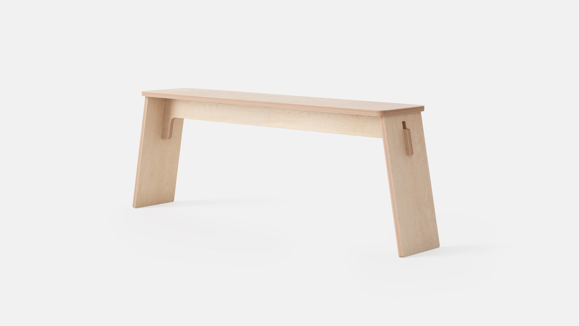
There are a few things I loved about these designs which I think are clever.
- The plywood legs are not straight
- The whole systems is a part of triangle. (The most stable structure)
- Looks good!
I decided to make the the smaller stool. Funnily enough, Opendesk only provides us with the DXF files. Nothing else, I was confused with the thickness of the ply to use, Tolerances of press fit joints. etc
After a bit of googling I found out what the file name means.
For example, take this NFB_JHS_STD_245x536x455_SA_AP_4_0_0_cad-1_18.000-0.0.dxf
Here the 245*536*455 signifies the overall dimensions of the stool.
AP_4_0 stands for the version of drawing file.
And the last 18.000 stands the thickness of the plywood.
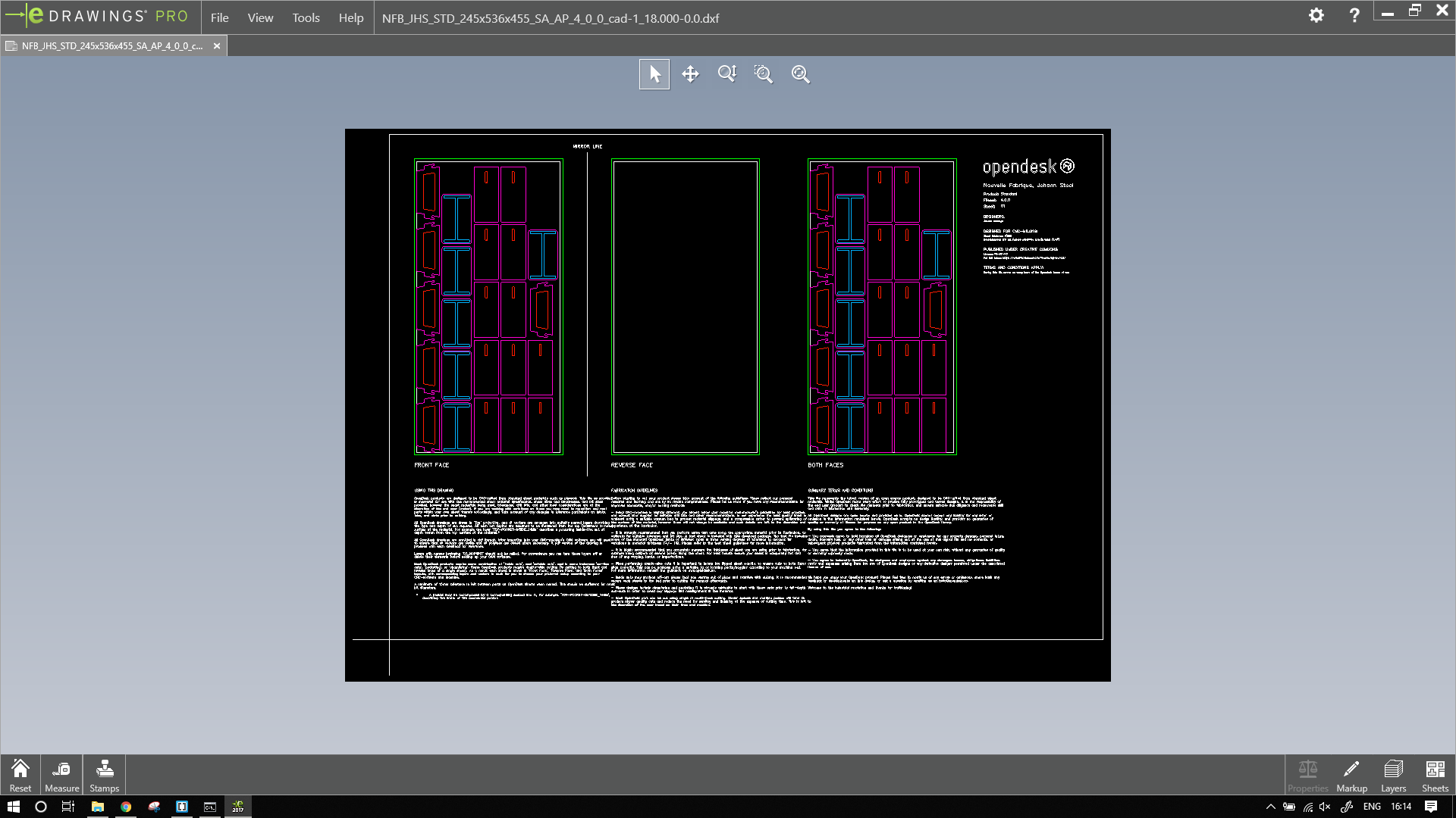
File from opendesk.
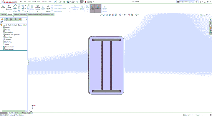
It looks too complex, but it is not. I decided to make my own design similar to this.
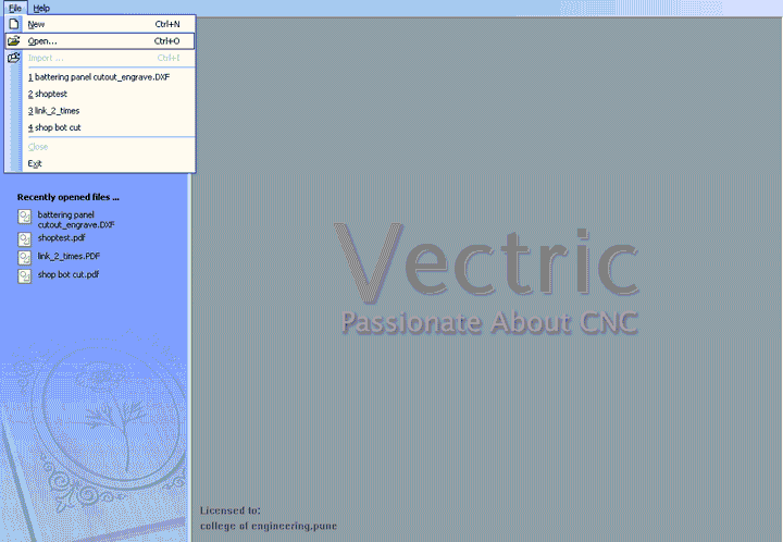
To make my design I first open the DXF file.
With the measure tool, I measured the basic dimensions of the stool.
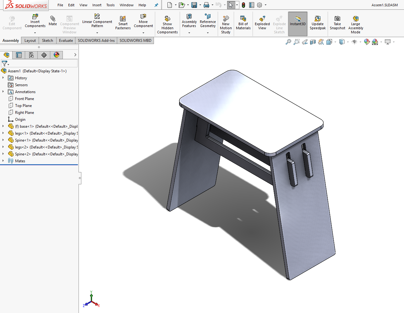
Then using those dimensions, I made my design.
The design cannot be directly replicated because opendesk has used a 18mm plywood, while I'm using an 12mm plywood.
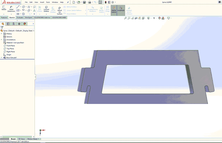
Also, my design has two spines rather than one.
I have added two spines because, I want my stool to be more durable.
The original stool was quite long, so I made mine a bit smaller.
For pockets, I set the thickness to 12mm because the shopbot has a kerf of 1mm, I would get a pocket of ~11mm. Which make my design pressfit.
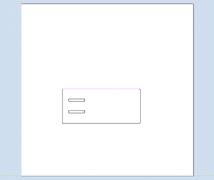
Here is my design,
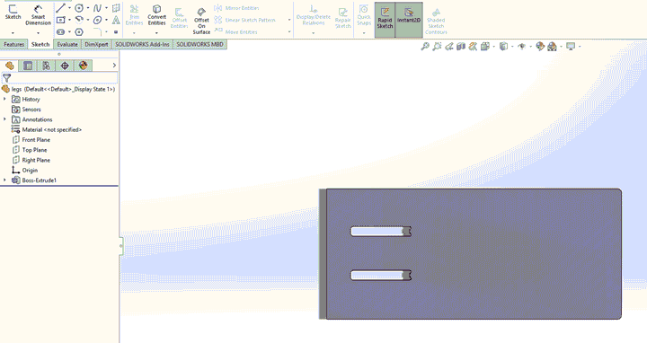
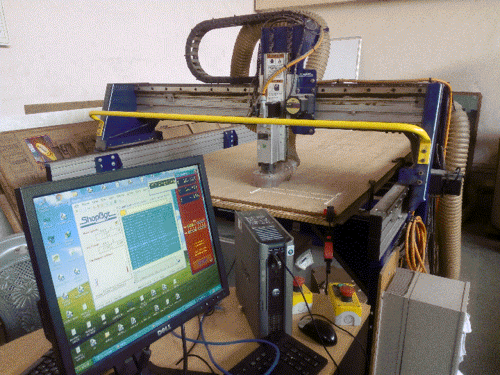
The shopbot in COEP lab is PRS alpha.
The machine has a bed size of 8ft by 4ft.
I made my files in solidworks.
After going to CoEP we were told that the the recommended files for the machine is PDF. To save the export the CAD files to PDF in solidowrks, We need to first make drawing from part. Then save the drawing as PDF.
Remember to set the scale as 1:1
Setting the scale anything less would result rescaling of the object.
Also working with Dxf is not recommended as it doesn't have accurate dimensions.
Shopbot usually works with a combination of two different softwares.
One to define the path to cut (Gcode maker)
Second to control the tool and follow the path (machine driver)
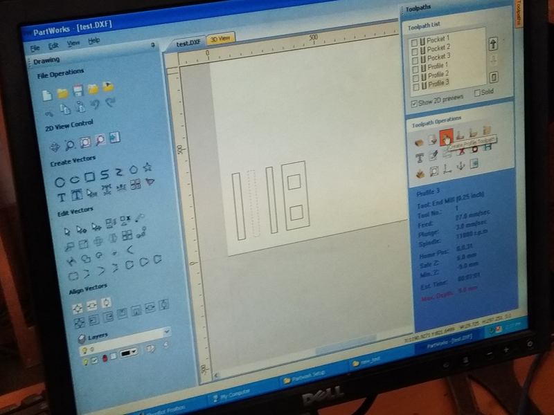
To make the gcode of path we used Partworks (2D).
There are other softwares like mastercam, vcarve etc. but partworks is recommended by shopbot.
To prepare gcode in partworks,follow the steps
: Open file in partworks
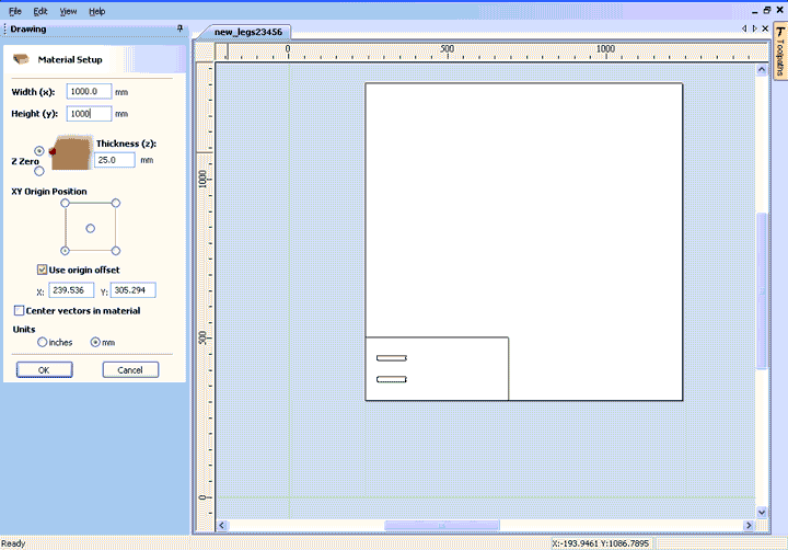
: In the material setup, adjust the height of material, for CoEP it was 4ft by 8ft. For nesting, I have selected the sheet size as different. While working we put the sheet before setting the zero. i.e we will set zero above the sheet. Hence set Z zero above the sheet. Since Z zero is above the material, he thickness of material doesn't matter.
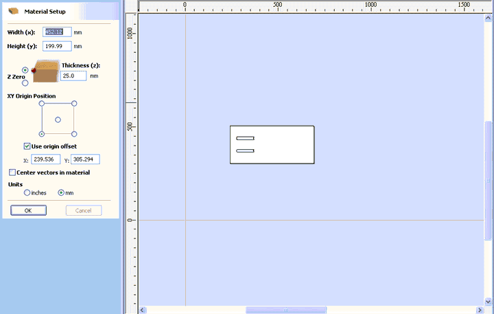
: Check the origin offset, this will help to work with the sheet.
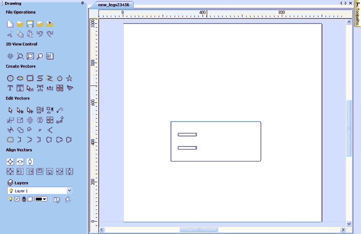
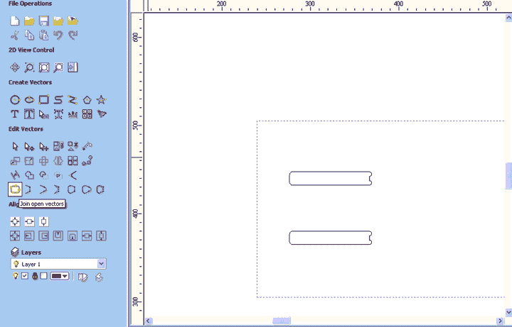
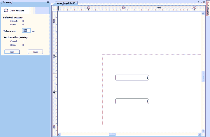
: Check if the all the continuous lines are a part of a single vector, if not join the vectors adjust the tolerance accordingly. In my case it was 2mm.
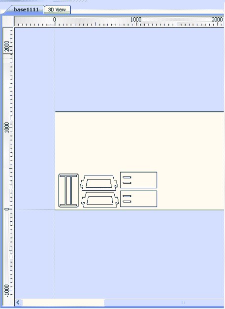
: I have nested the files as shown to save the space.
: Use Ctrl + C and V to copy and paste many parts into one file. Nest the files properly.
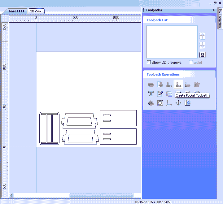
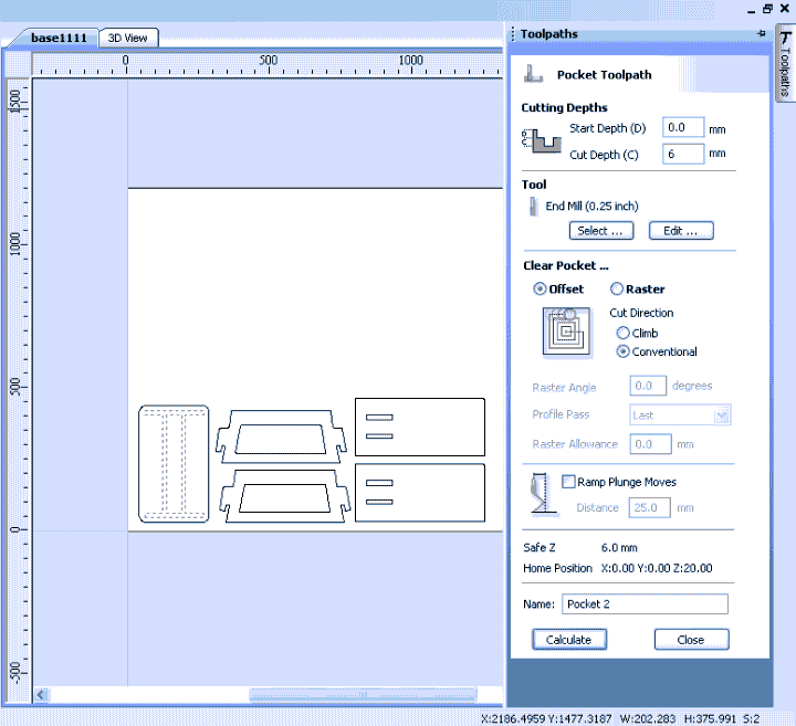
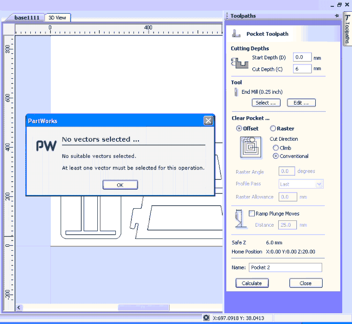
: To create tool path, click the toolpaths, as per the requirement select the toolpaths. For me first I have created the pocket toolpath. The cut depth is the depth of pocket for me, 6mm.
: Edit the properties of the tool using the edit under tool.
normally, the default values of tool are not the same as recommended by manufacturer. The value we used are recommended by the manufacturer for longevity of the tool.
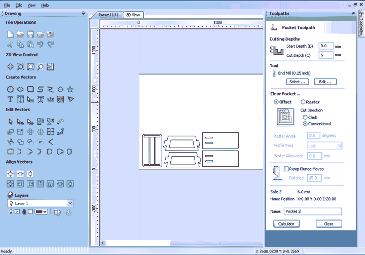
: After editing/adjusting the tool, select the calculate the tool path. I made a mistake here by not selecting the profile which I wanted to pocket. To do this use the mouse button select the profile and then calculate the tool path.
The above screenshot shows the settings of the machine
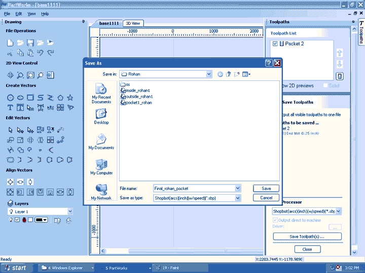
: Then check the tool path in tool path list and click save.
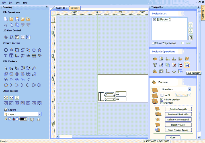
: Now save the tool path in your favorite location
: Repeat the same for inside cuts and outside cuts, remember to select the proper option in tool paths.
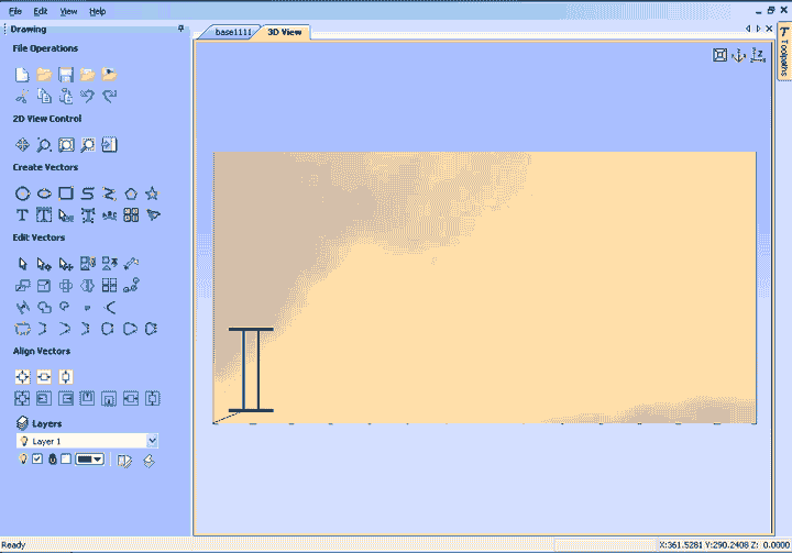
: In 3D view you will be presented with a representation of all tool paths. Check whether all the paths are correct, check for intersections. etc.
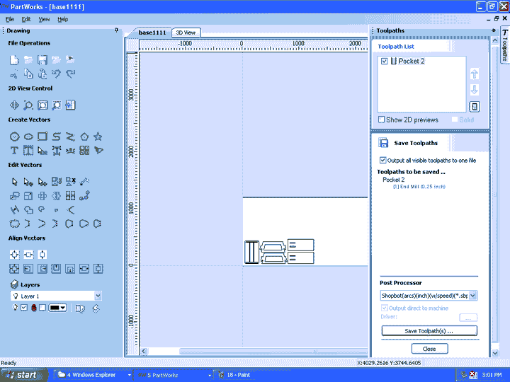
: Then save all the tool paths individually. The file format saved by partworks is .sbp (shopbot file)
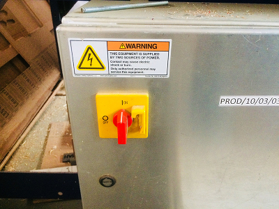
Shopbot requires 3 phase power supply. There is an on switch, by turning it to On position, shopbot is switched on.
In the console, select the shopbot keypad. This helps to easily position the motor.
The D-pad helps to move the motor in XY plane while the up-down buttons move the motor in Z axis.
This can also be done by keyboard. The XY plane with arrow keys and Z axis with page up and page down key.
To set zero, move the router to the required position, then turn on the spindle and press page down until the bit touches the ply.
The load the part file in the console.
Logic of working is that first machine all the inside cuts and pockets. Then finally cut the outside.
This keeps the plywood stable while cutting
To secure the plywood to the board, use C clamps or screws.
Then load the part file in the shopbot console
Finally my stools
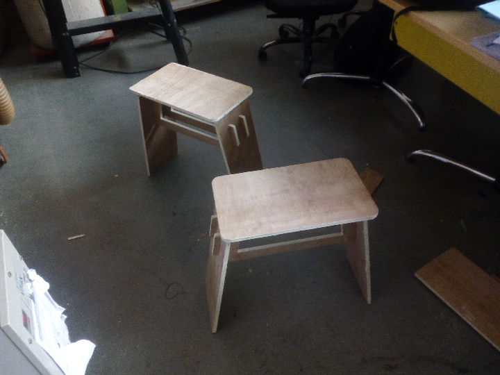
All my files are available to download here