Aim:
The study the basic aspects of controlling a machine
This week was a bit out of my league, I was willing to work on this one, but later after the assigning of the roles, I had shifted to the mechanical work.
Hence the entire working of the interfacing and electronics could be found on the arm's page, and on the pages of Arefin and Rutvij.
Learing outcomes.
This did not do much as stated abouve, but I got to learn a few things, listed here:-
- Initially I learnt about the methods of interfacing using various protocols in terms of softwares.
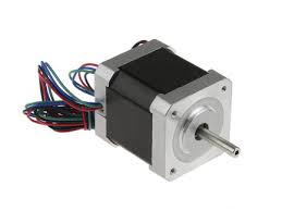
It started when we had to test if the motors were running using any interface possible.So we intially had the Nema 17 motors at our disposal so we had to test if they work with the basic firmwares that we had.
For this we I had been trough examining the Mach3 CNC firmware, that was said to be used for most of the X-Y plotter machines and had seen the functioning of the same for Arms.
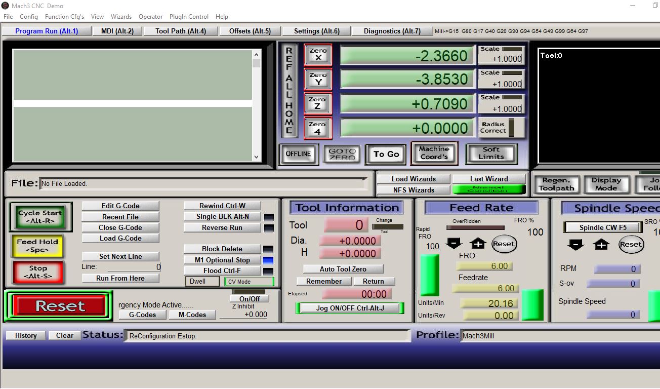
But over time we realised that it was too difficult to work with as it needed a dedicated serial port along with the motor drivers, that we were quite unable to manage.
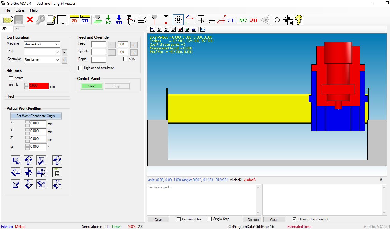
So for the next part, we went with the software named as GRBL Gru, this is again a softwares basically used for X-Y plotters, we just wanted to test the motors.
So we followed the schematic as seen here..
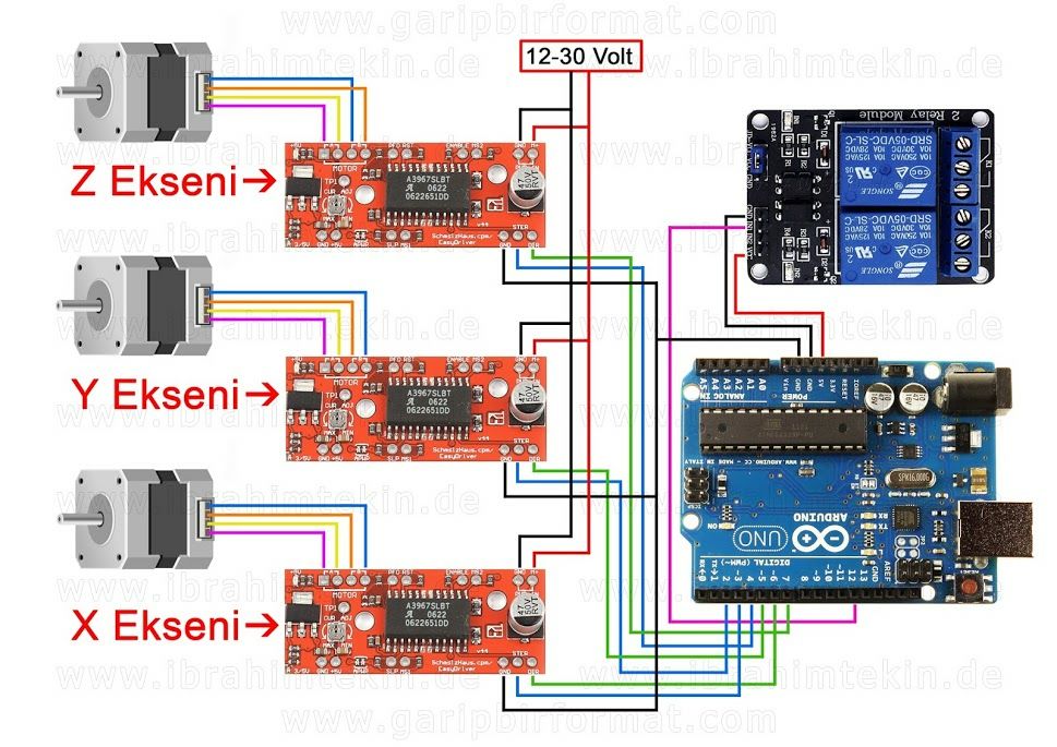
After which a hex files that contains the perpherals for the interfacing, this was done through the x-loader after which we connected the motor driver, as seen in the schematics. and as we pressed the JOG buttons on the GRBL software, which led to the motion of the motors.
This was our initial attempt of interfacing the arm to with software peripherals.. -
The next thing we were stuck at was how to run the ARM if we feed a design through it, the logical answer (other than the ROBO language) was using G-codes.
But as well known the g-codes work with the positioning of the end effector, in terms of the cartesian co-ordinates(as the X-Y plotters work)
What we needed was the endeffector has to move according to the catrtesian system but the machine to move into spherical system.
After a bit of lookups for the solution, we came across motion kinematics, that included inverse and forward kinematics.
What are kinematics and it's types.
Kinematics are the mathematical relation between two or more co-ordinate system, that can be interpreted for the driving the machines, that relate with those.
Kinematics for Robotic Arm
Forward Kinematics
Forward kinematics is basically math that directs the end effector as per the instructions give to the motor, respectively.
For example:- We instruct each motor with definate step angles and speed(in case of servo motors), and accordingly the end effector moves.
Inverse Kinematics
Inverse kinematics on the other hand works entirely the other way around, here we define the co-ordinates of the endeffector, and the math is in such a way that the angles for each of the motors are calculated.
This is basically done calculations using trignometric geometry, where we define movement of each arm in terms of triagles, where then we generate the logics for each, the details of the math could be found here.
Hence we had our answer to use inverse kinematics for the interfacing and the motion of the arm, yet how was the major question that was solved by the interfacing team of ours.(links of their pages are mentioned above.) - Out of which what I learned was about the drivers used, and how actually the interfacing works, and what difficulties we could face if we have to work with anu machine as big as an arm.