Aim:
To build the designs that were developed in the previous section
Task 1:
Manufacturing the mechanical parts.
Sub Task:-To work with the laser cutter.
For this there was very less to describe actually, the major of the second sub assembly was manufactured in the the acrylic on the laser cutter, according to the availability of the material.
The job was done on the local chinese machine that we have the SIL laser, where the speed and power was as mentioned below..
This was the power and speed out of the data we had calculated in the assignment of computer controlled cutting After the job was done I had following parts as seen in the figure..
Sub Task:-To work with standard available components.
The next step was working with the standard components, in my design the all the bolts were of the size M6 in diameter and with varried lengths according to the point of application.
For the project there were a lot of components that were econimic when purchased rather than manufactured, since all of them were available as standard components, these included:-
- The channels for feeder, here I prefered to use the standard PVC channels, which were readily available
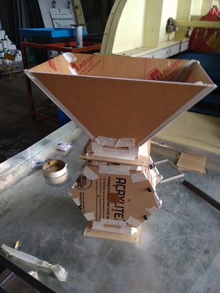
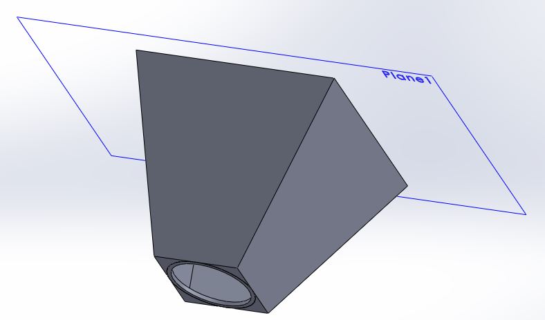
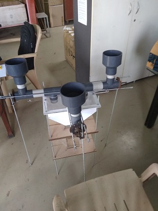
- The hoppers for raw material, this was prefered to be bought from the market since, the opening of the channels for the feeder were circular, and if the hoppers were to be cut on the laser cutter the nesting of those would have been difficult to make from rectangular to circular hole, something as seen in this design..
- Bearing, studs were naturally to be bought as standard components.
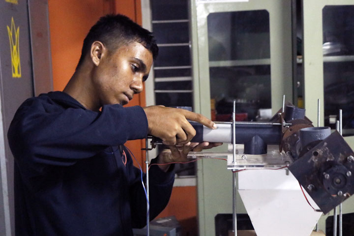
Sub Task:-To work with mannual manufacturing methods.
For the machine I had few components such as bearing holders that would have been tedious and costly, so I decided to manufacture it manually, the material was purchased from scrap and then I had conducted machining processes over it to achieve the desired jobs.
These jobs included bearing holders, shafts, feeders, and motor mountings.
For this there was one part that I had made with a premetive method as we term "JUGAD" in local language.
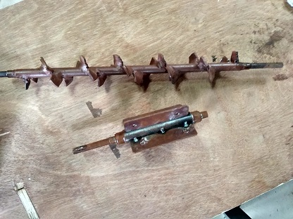
it was the assembly of the feeder, basically the feeder has to be manufactured through the process of turning, but now the case here was the height of the feeder was 45mm hence the entire block had to be of the diameter 45mm, and the major part was the innner shaft, which was expected to be of 15mm in diameter, hence the material had to turned from 45mm to 15mm.
Hence this would have been a heavy loss of money, so for the same I decided to make it out off jugad..
I basically purchased a shaft of 20mm in diameter, turned it as per requirements of the bearings, and then carved a helix that would match the pitch of the feeder, then I welded plates that satisfied the required height for the feeder to work,
this may not have been the perfect method for manufacturing but it solved my purpose at a lower price.
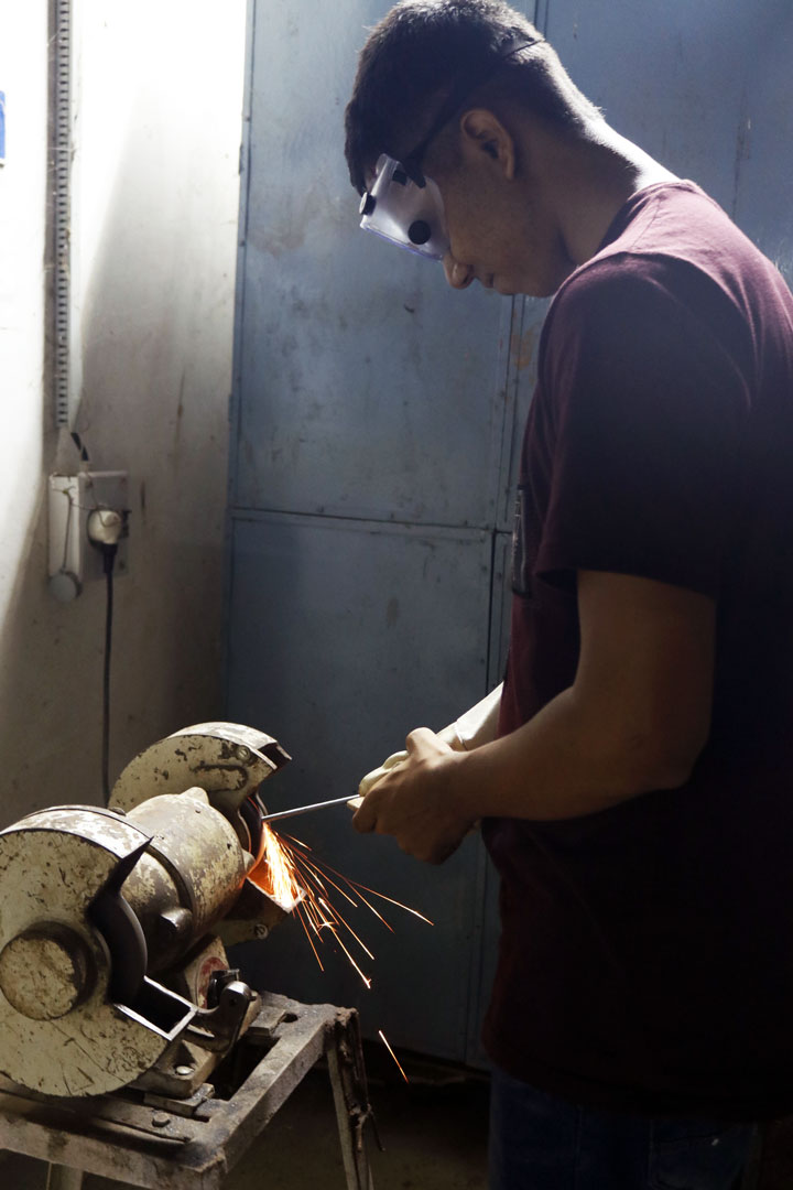
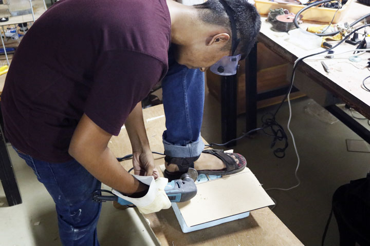
Also since the project also had lot of genric materials, I had done bit of error improvements in the lab itself, those included grinding, cutting etc to get few components in the right place.
Sub Task:-To work with 3D printed objects.
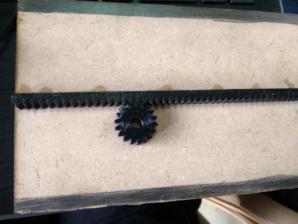
The object that I had to 3D print was the rack and the pinion, it could actually have been possible to cut it over the laser cutter but the limitation would have been sticking to the standard sizes of the materials, rather not the sizes I needed, hence I decided to 3D print the assembly.
Which was pretty simple to print and didn't take me more than 1 hour.
And this was the following that I had recieved..
Sub Task:-To work with arrangements in the assembly.
Here in the assembly I had kept few parameters that could be varried as per requirement, since this was a prototype, few of the things would not have been precise as expected, so the better way was to keep open tolerances for the same that could be altered over a wide range.
This was also to be done to overcome the manual errors that could have been generated during the assembly(which were, as expected).
Considering the same I had made the basic supporting and load carrying structure in threaded studs, this gave me the freedom to arrange the entire assembly according to my will and removing possible errors and also one more freedom was added, I got to decide that which member of the assembly would bear the load of which memeber, and rest I took over the studs.
The other thing I noticed was, as the load was taken over by the studs, the assembly remained quite steady even at heavy loads of the MS components, this was unplanned, but I was happy to see that doubtful issue being solved.
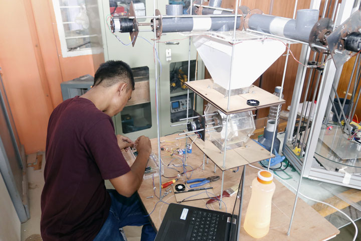
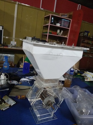
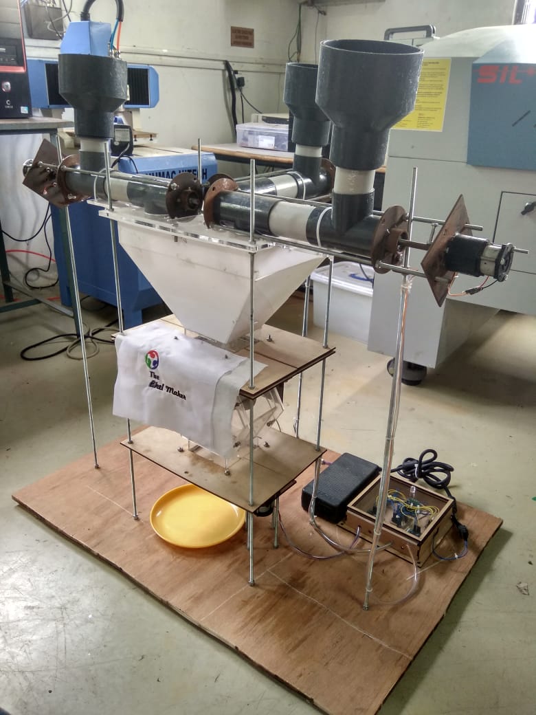
Hence all the considerations, on time changes and errors had led me to the final assembly of the machine which replicated my dream as seen in the CAD design..
Task 2:
Manufacturing the electronic parts.
Sub Task:-Getting the circuit ready for the show.
For me the electronics manufacturing had went pretty easy, since all the design and production work was done in the Output devices week.
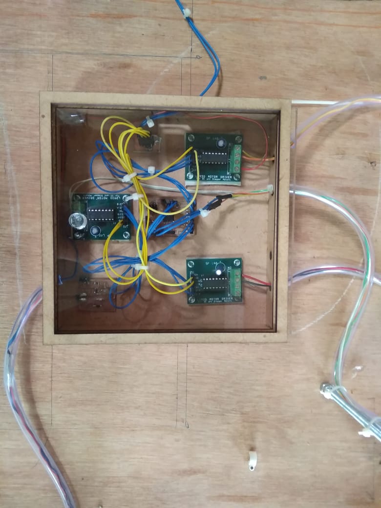
Here the controller board was the one I had designed for the requirements of my project.
Along with this there were three commercial boards those were basically the motor drivers "L293D", these I had used directly as I was reluctant to make it due to their complex design that I was unable to figure out...
Following attached is the datasheet.
Also the initial test program was burnt on the board, to ensure that it was working, now the only thing left was to program the board with the final code.
For this I had written few logics that were assumed to be working for the machine, in the shortest amount of time, which are listed as follows.
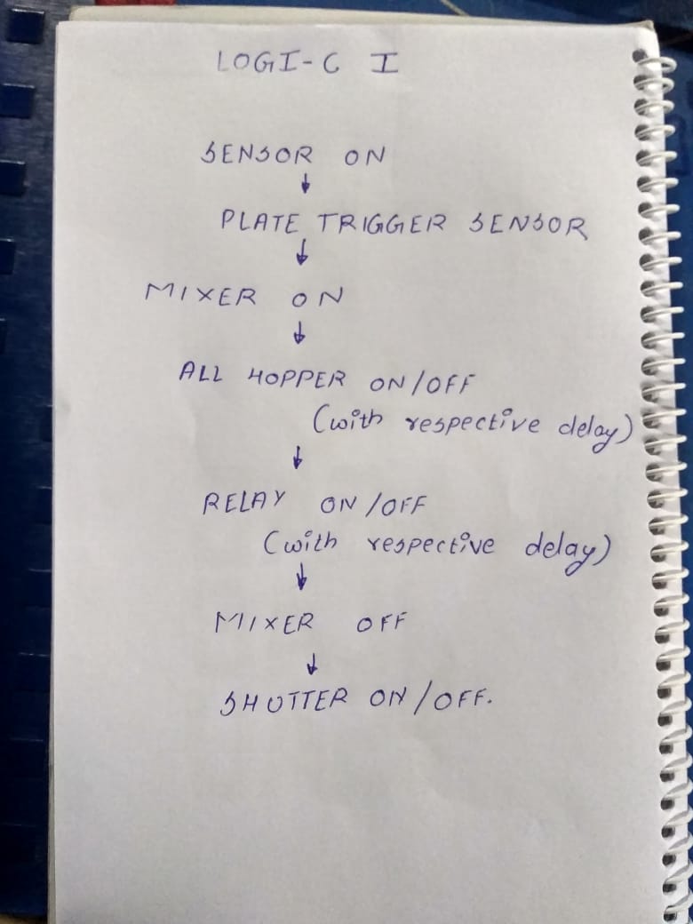
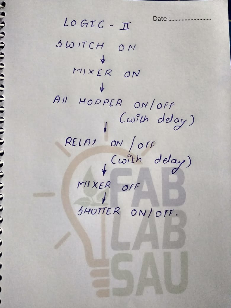
Out of which I found the second one to be favourable for me, where the entire machine would be triggered once the plate is kept under the machine and then I went on integrating the logic into codes on arduino.
After which I had recieved a code as seen here
And for the pre testing of this I was also suggested with one good method, it was to check the output of the motor in the serial out, as seen here...
Task 3:
Testing the final run
This actually was one crucial part, which actually had been pretty difficult, since the machine had a lot of errors, and for the initial runs it had killed me off.
The testing went the following way:-
- First the hoppers were tested for the direction purpose, where they dropped the material down, for this I had used a standard 9V battery box and connected mannually to check with the directions, which I had noted for final program.
This was the initial testing where I was quite satisfied, since the material was finally falling down, as seen here:-
I had tested other motors using the similar procedure. - The next was to test the triggeing of the program using the sensor attached at the bottom.
For this I had attached an LED to the one of the output pin that was supposed to be triggered 1st, the code was so that once the plate goes beyond a certain distance the machine would be triggered, and hence the LED would light up.
Horray it worked!!
Now as a status of the initial runs, I had all the motors working, in perfect condition, along with the triggering mechanism.
And the task left was to load the final program and get the stuff running.
After this the task was to generate a video of the efforts, and the working of the machine that could be seen here...
Few amendments..
After my initial assembly and testings, there was actually a thing that I had forgotten, and it was the packaging of the entire stuff, basically apart from the asthetical look of the machine, a proper packaging was necessary for perfect operating ergonomics.
Hence following were few paramerters that I had applied to get the ergonomics quite sanding..
These amendments actually helped me debug the issues faster since there was no stastical mess around the project...
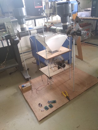
After the entire wrap this was the seen machine that I had..
A small token of gratittude
The project was not actually a product level success, but on the initial scale of prototype I was satisfied with the thing it was able to pull off, and the concept it was able to proove.
For this I was actually not the whole and sole behind the prototype, there were a lot of people who actually had stood up for the help when needed.
- It was Mr.Anil Gosavi (my dad) who had helped me a lot with the mechanical setup, to get the thing standing.
- Few of my collegues also had helped me a lot, when actually I had gave up on the work due to the loss of patience
It was Rutvij Pathak, who had helped me get the electronics working and debug most of the issues with the running of the motors.
After then it was Rohan Rege,who had helped me debug the issues I had during the assembly like few of manufacturing methods, and also with the programming where I had to edit few of my logics and write a code from scratch.
Also many of my collegues had helped at respective times when it was high on the mast.
Conclusion:-
After the macchine was ready, it was or rather it is not at the level that it could be directly released on a roduct level,hence follwoing seen is the current capability of the machine:-
- The mahcine is capable to deliver a normal plate of bhel.
- It is capable to follow the logic of being triggerd by a sensor and the follow the entire logic of procedure of bhel.
- The mahcine is durable enough to stand against generic use.
- It solves and proves the basic concept of auto batch system.
Apart from this the machine actually has a future scope of working that I was unable to pull on due to lack of time, knowledge, tools, logically budget.
There were few generic things that had to be skipped in consideration of the budget, hence the machine that stands is basically an initial prototype and can be debveloped in following areas:-
- It starts with electronics, here I had used few commercial motor drivers, they could actually be customised as per needed, this I was unable to do due to actual lack of expertise in electronics.
- The next is the materials used, the materials that I used are actually food grade under the current condtions, but are actually not distiguised as ones, hence the materials really need to be worked on.
- The physical packaging of the machine currently seen is pretty crude this was actually avoided in order to examine the working of the machine which would have been difficult to see if it was packed
- Well planned working for the packaging and workgin ergonomics, for the machine to be asthetical.
- Ther has to be propper measurements taken and then the machine has to be arranged, which as seen is on threaded studs, this was a provision for lie improvement.
- Addition of the missing components that were avoided for loss of budget such as solenoids, and it's assembly