Aim:
To make a run through the theorotical designs of the machine.
Task 1:
Working with the Mechanical Design
This machine was basically more of a mechanical design, comparing to the electronic and programming elements.
For this there was a basic need for the mechanical design to be perfect, for this I was effectively guided by one of our consultant, Mr Anil Gosavi, who actively helped me get thorugh the path needed for the design of the machine.
The procedure began with initially analysing the most basic components that we needed, they were the ingredients that the Bhel was composed of, we needed the volumetric composition of each ingrediets, to roughly define the ratio of the components.
This we did by purchasing a Bhel from a vedor, and then calculating the volumes, we got our first results of requirement
After this the next task was to go with how the basic mechanism was supposed to work, this we had actually defined in the concept page., but as we went on the mechanism defined there was bit heavy when it came to manufacture.
Hence there were ammendments in the mechanism on a major scale.
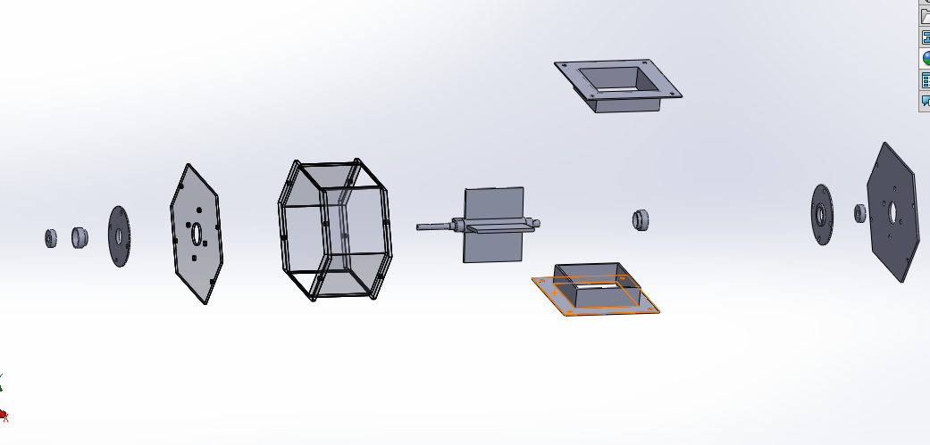
For the ease of designs we had split the assembly in upper and lower parts.
Sub task:- Designing the upper part.
The upper assembly included the following parts.
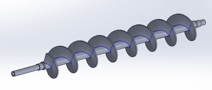
- The feeder:-
This was the most important component in the entire assembly, the design procedure has been explained in detail in the Cad design week
The feeder was to pass specific amount of material for consistant taste.
Initially the suggested mechanism was to use was a shutter that could open for a specicfic delay to pass the required amount of material, but that would not have been specific in terms of the quantities.
Hence feeder screw was prefered mechanism for the job.
- The hoppers:-
These were the ones where the raw material was going to be stored, hence the volumetric capacity was found from the data calculated from the previous calculations, and were designed to have a stock of atleast four servings.
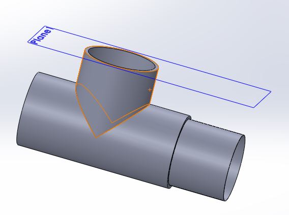
- The guideways for the feeder:-
The feeder needed a duct through which the material was supposed to pass, for this I refered to a standard pipe, made out of PVC that could contain the feeder inside and the material would ride through it.
This was basically a T-joint made out of PVC as seen here.
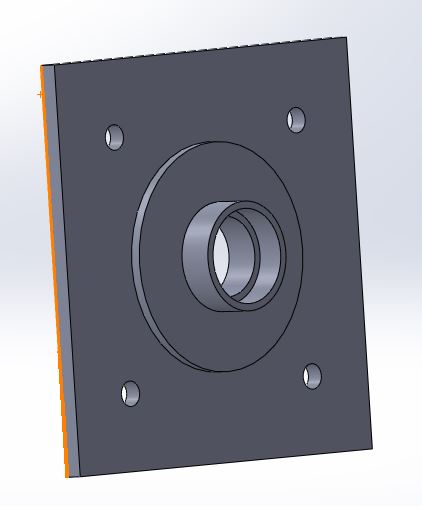
- The bearing assembly(consisting of the bearing holders, flanges and the motors):-
This assembly was pretty easy and had only one task i.e to ensure smooth running of the feeder system.

Sub task:- Designing the Lower part.
The job of the lower assembly was to collect the raw ingredients dropped from the upper assembly and then mix them up along with the liquid spices in the mixer, and then deliver it down.
This assembly consisted of the following parts or mechanisms...
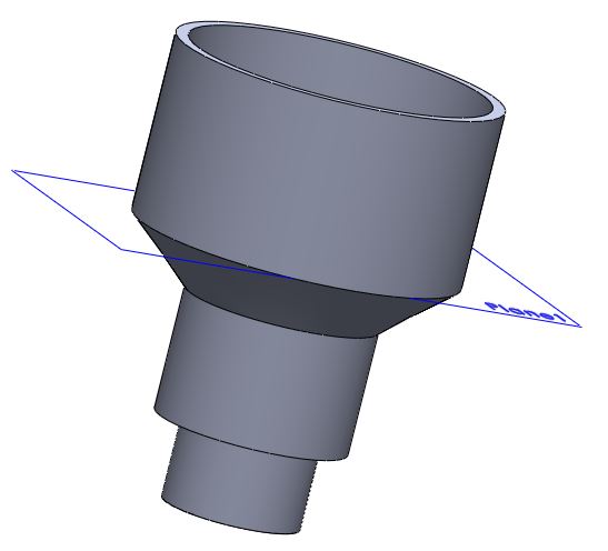
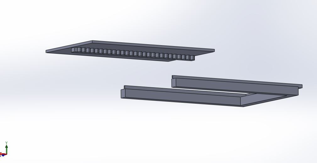
- The main hopper and it's plates:-
This hopper had a basic function to support the upper assembly and then guide the solid mixed material to be mixed with the liquid spices in the mixer.
The assembly consisted of a guiding hopper, with flanges to support the assembly as seen here.
- The mixer:-
The mixer had a crucial role, it had to mix all the raw ingredients to give a perfect taste as required.
The basic requirements were, to be modular and easy to fix or clean if something went wrong, so was designed with detachable flanges, where the blade was mounted.
Hence following was something I had got as a design cosidering the requirements.
- The Door:-
This was basically a shutter, driven by a rack and pinion mechanism.
For this I had a pinion custom designed according to my need, and I wanted this to be 3D printed, and in parallel, a rack for the same.
The major consideration here was to have an optimum length and a sustainable travel in order to open the shutter completely.
Considering the above I had the design ready.
The design process for the rack was bit different than the ones opted before, according to the traditional method of modeling I had to calculate all the parameters for both the rack and the pinion, which would actually have been difficult for me since I had never studied them before.
So rather I was suggested to use a parametric file that was predesigned in open SCAD, it was a pre written program where the relative math for the alignment of the meshing teeth was written.
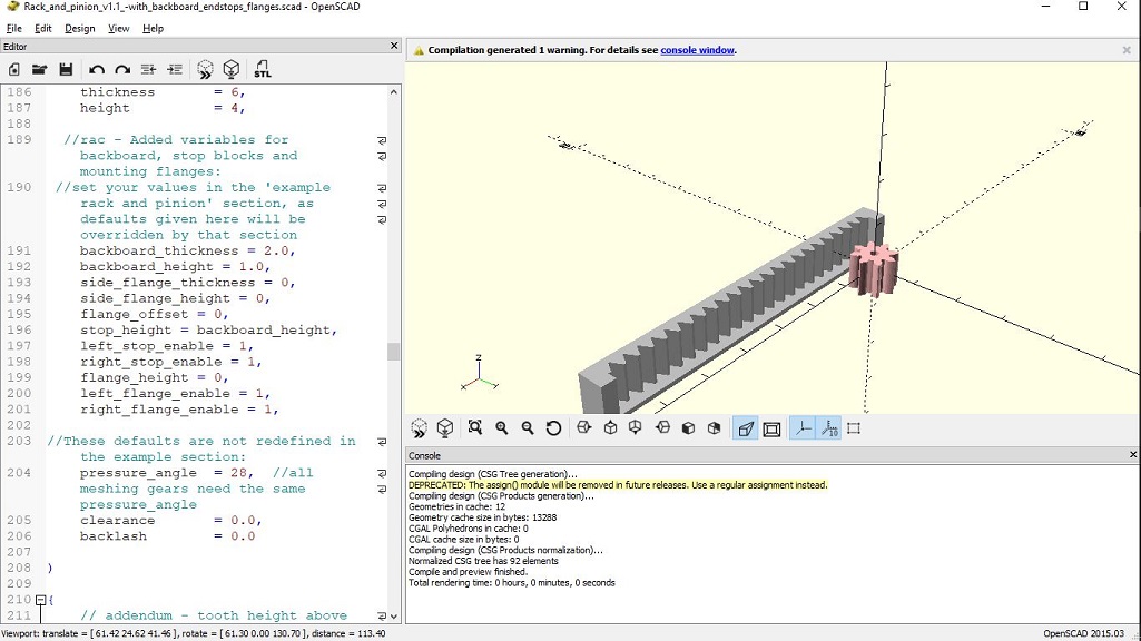
Initially in the file the modes for the gear and the rack had to be defined, which were later being used while specifying the other parameter, basically these were the governing parameters for developing the gear and rack.
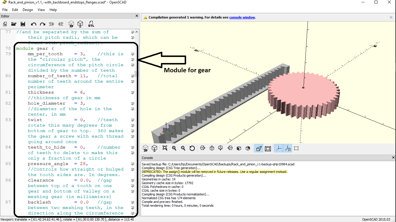
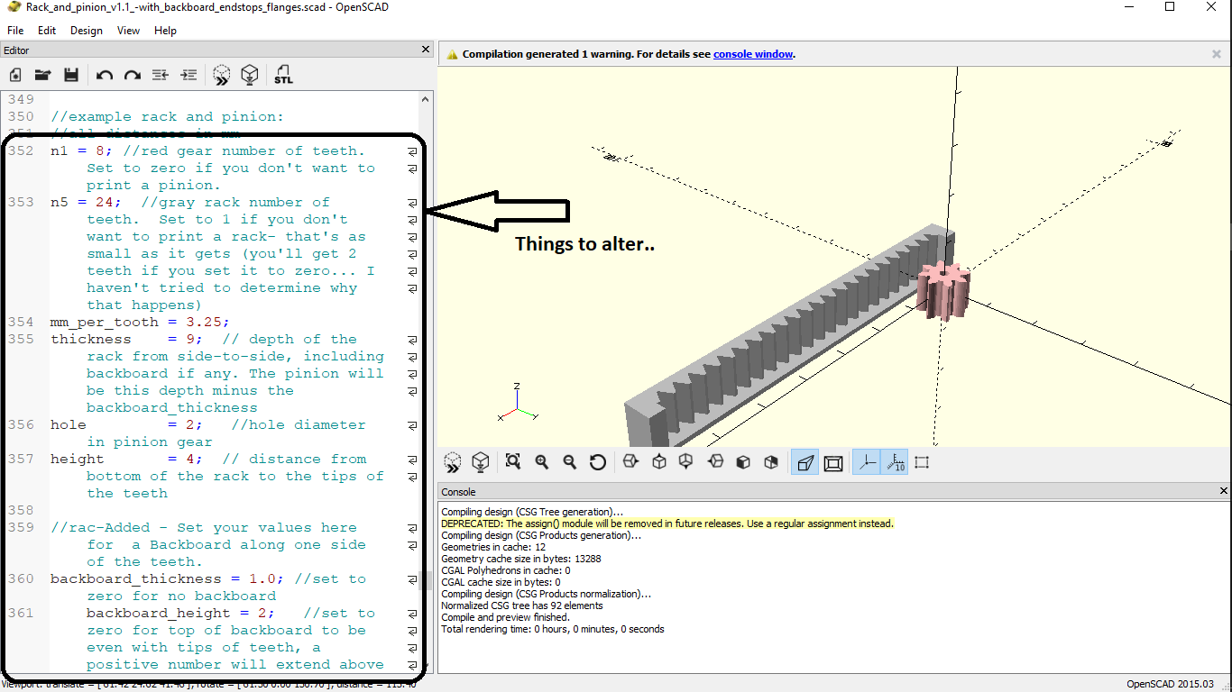
Later as we went down we had the editables for the actual dimensions for the rack and pinion, here as we specified the dimensions according to our need, both the rack and the pinion changed.Which could be viewed in parallel, by hitting the preview button.
Once the rack was satisfactorily ready, the step was to export this as STL file for 3D printing, but before that the file had to be editted to make a perfect pressfit on the shaft of the motor, basically a keyway had to be made.
For this we found another SCAD file that was dedicated to convert 3D STL files to 2D DXF files..
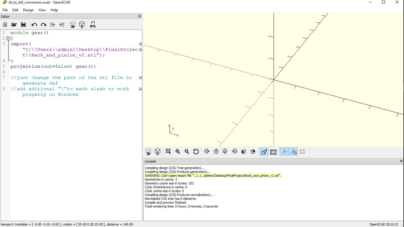
Using the above I converted the DXF file of the STl and then rendered it to develop a keyway through it..
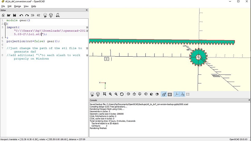
Inconclusion the following method actually turned out to be a better solution for me.
For further help I have uploaded the SCAD Files here.
For the same I needed a shutter for the actual operation, along with its guideways, which I had planned to design as seen here.
After the success of the design of this assembly, it was a conclusion to the mechanical parts of the project, and the next step was designing the electronics.
Task 1:
Working with the Electronic Design
This was actually a part I was very sceptical about, because I had actually been through this process, only during the course of FAB academy, and had no initial backgroud as I had a bit in the mechanical designs.
For this I was initially well suggested by one of colleague that I would have two or rather more versions of the same board.
Also considering the experience out of the previous assignmnets I had following things to prepare before I actually designed the board, those being:-
- Reading the data sheet of the ICs to be used for the required pinout
- Finding the basic required components for the initiation of the circuit, before we add our required peripherals
- Listing out the number and position of analog and digital pins in order to understand the alignment of the sensors and the actuators.
- Listing out the power sources and other necessary information
Considering the above I had sat to design the version one of my board...
Electronics Design:- Board Version I
Duting the design of this board, I actually had a different mechanical design it consisted of the following components:-
- 4 Motors for the hopper
- 2 Motors for the acctuators
- 3 inputs(ultrasonic sensors + switch)
- 1 Relay
Considering all the pin outs for these respective components I had decided to go with the atmega 328 processor the one which was available with us. For the same I had to refer to the datasheet inorder to go through the required details.
After which I had designed my board, with a few difficulties that are mentioned in the process of the design of that individual board, which could guide the entire procedure for the problems and their solutions.
Procedure could be found Here.
After the entire session of problems and solutions I had this following design and a printed board.

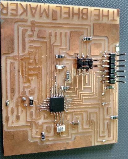
There were actually issues with the programming and interfacing of the board, and it was being very critical to debug.
Hence the this other design i went with was quite optimised and with a familier circuit to debug.
Electronics Design:- Board Version II
There was a significant change in the design of this version because till then I was working on optimising the mechanical design.
This led to reduction of the driving components upto a great margin.
Hence I finally had only following moving components...
- 3 Motors for the hoppers
- 1 motor for the actuator
- 2 Inputs (1 Ultrasonic sensor + 1 switch)
- 1 relay
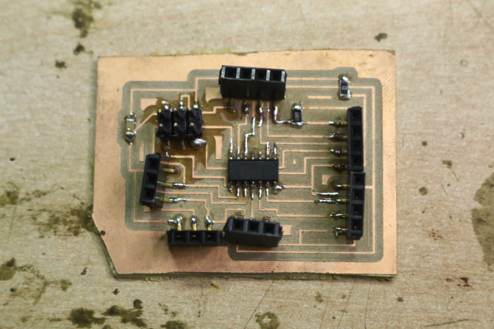
For this change I decided to work with a little familier IC, Attiny44, this was pretty simple to design and debug, since we had a ton of experience working with this one.
This was the one I also used as the programmer board for my Output Devices assignment, hence I had very little to design apart from the procedure explained in that week.
Therefore I had got this board as my final board..

This concluded the design part of my final project, and what was now left was the manufacturing and the assembly.