The first task this week was to read the Attiny Microcontroller's datasheet and document what I learned.
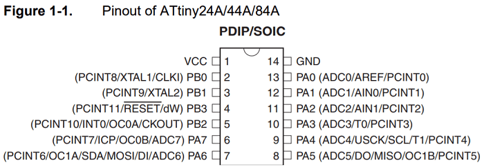
As soon as I started reading I already had useful information, the pin configuration page shows the different types of inputs and outputs that will work with each pin.
For example one of the options for pin 8 (PA5) is MISO (Master In Slave Out) where data goes out of the slave and enters the master.
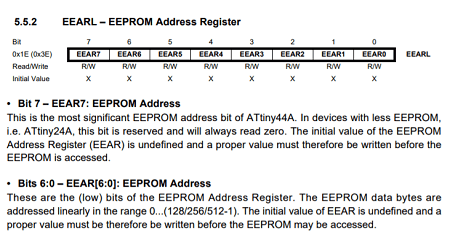
As I continued reading I found the pin description area where it states more details about the different types of ports (VCC, GND, Port B, Port A, RESET). As I reached the general info, block diagram and architectural overview I sincerely felt a bit lost since its the first time I'm seeing some of this terms and am not familiar with AVR Architecture. Past this point I undestood maybe half of what the data sheet said, I undestand what the information is about (types of resets, sleeps, toggling, reading, writing, etc and how to do it) but its super specific and there are so many options(286 pages).
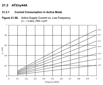
Almost at the end of the datasheet you can find the power consumption graphs which help calculate cost efficiency in larger projects and also make sure your source can supply the voltage your micrcontroller will demand.
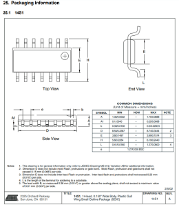
Almost at the end I found more general information about the Attiny such as its specs and the packaging instructions.
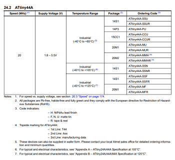
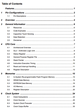
Finally, the last part of the datasheet is the index(Table of Contents) which in my opinion should go at the start of the datasheet.
The most important information I got from the data sheet was that all the information I need when handling a microcontroller can be found in the datasheet and its a very useful tool since it allows you to access only the information necesary for your projects. Obviously you learn more and more with practice but for a beginner its like having a dictionary that shows not only meaning but also the grammar rules regarding each word.
You can find the Attiny's datasheet:Here!
After reading the attiny44's datasheet I pondered about a better way to learn about micro controllers:
- Is there an easier way to read through a datasheet or a faster way to become familiar with them?
If there isn't I would like to learn:
- A specific order regarding the must knows when it comes to Microcontrollers and their programming interface and software.
Once I absorbed the information regarding datasheets I was ready to program.
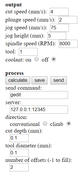
At first I wanted to make and program the Satchakit board so I imported my png into fab modules and set up the parameters for the Milling machine and exported my .nc file (g-code).
Parameters:
- Spindle Speed: 8000rpm
- Cut Depth: 0.1mm
- Tool Diameter: 0.1mm
- # of Offsets: 2
Once everything was set, the X,Y and Z zeros were marked and my PCB was secured I started the milling machine.
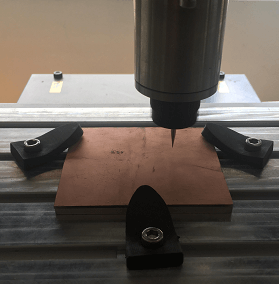
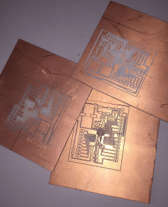
Right from the start it was a disaster, board after board came out with problems as the tools on the milling machine kept breaking or the bends in the boards wouldn't allow the path to be carved properly. As the week progressed I started getting nervous so I decided to program my hello_world board instead to make sure I completed the week's tasks. After I could retrace my steps and finish my satchakit.
After the minor setback I was back on track so I started my Arduino IDE(version 1.8.5). Soon I found out from my peers that programming with the Arduino IDE (version 1.6.4) was much easier so i downloaded it.
Before programming my board I installed the Attiny library for the Arduino IDE.
I did so by: File > Preferences > Paste
"https://raw.githubusercontent.com/damellis/attiny/ide-1.6.x-boards-manager/package_damellis_attiny_index.json"
in the Additional Boards Manager URL's > OK
Software side was ready so it was time to get to the hardware.
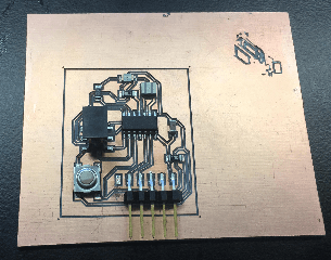
This was my Hello_board from week 7.
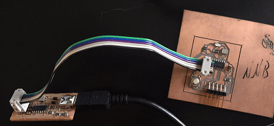
Next I connected the FabISP to my laptop and the fabISP to my Hello_World.
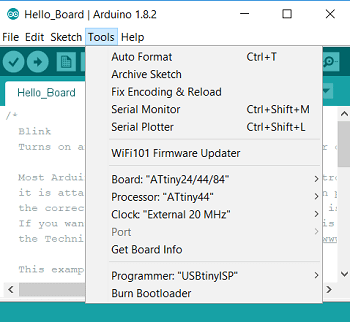
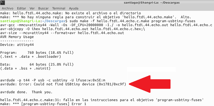
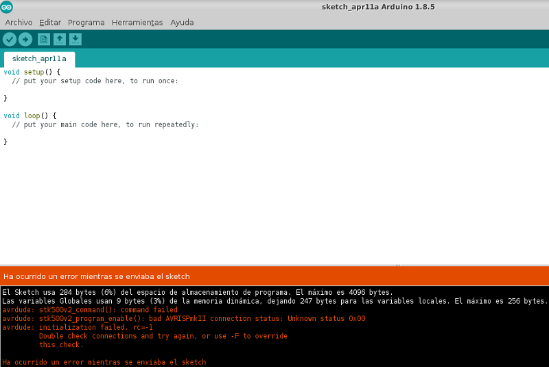
Before I could upload my code into my microcontroller I had to do something called "Burn the Bootloader" which lets you program the microcontroller.
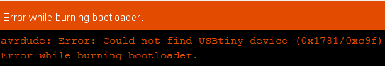
The error meant something was wrong so I started checking everything:
- First my hello world board had some soldering problems so I took out the multimeter and checked the board for missing connections.
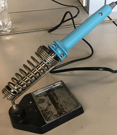
Quickly I found out there was some problems (2 legs from my attiny, a missing pin in the 2x3 header) so I took out the soldering iron and fixed them.
Once my Hello_World board was working properly I took out my FabISP, FTDI and AVR connector and tried to burn my bootloader again.
I was getting used to getting that error.
This time I decided to check if the problem was my FabISP although I was pretty sure it was working properly as I could program it in week 5(although I could only do it with my instructors computer).
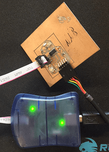
As soon as both green lights were on I knew the board was working so I tried to burn the bootloader but my computer wasnt having it... you guessed right! couldn't find the AVR programmer either. Next I decided to try with my instructor's Linux to see if it helped. First I checked if it recognized my board, it did.
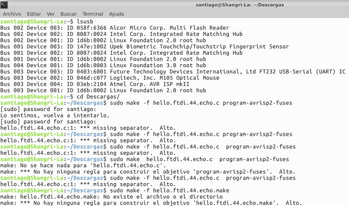
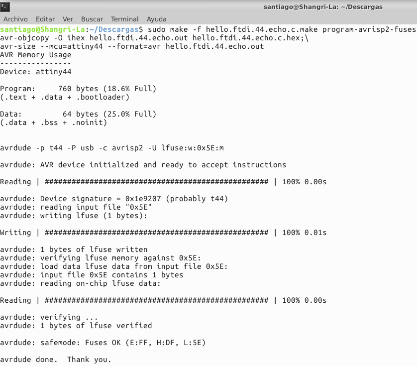
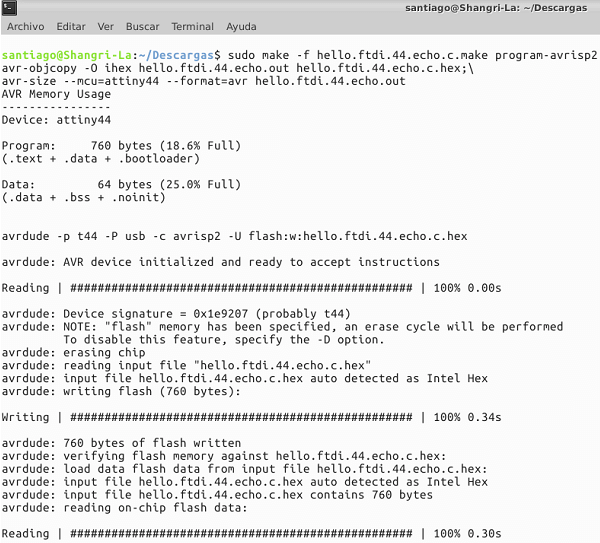
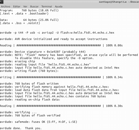
Next, I attempted to burn the bootloader directly from the terminal.
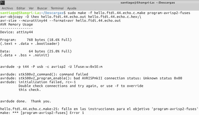
Even with the AVR there was an error so I quickly tried my FabISP.
Hello darkness my old friend...(Back to the AVR)
At this point I was both confused and relieved, my board worked although it was not working consistently. At least I burnt the bootloader, now it was time for the code so I tried uploading in the Arduino IDE. It failed but at this point I wasnt stopping unless the board was broken.
Next I opened the blink example from the Arduino IDE and changed the pin from 13 to 7 so that my LED would work. I used the datasheet's pinout reference to find out which arduino pin would they be in the Arduino IDE.
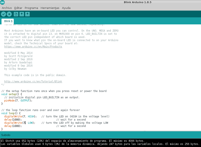
At last my code uploaded. Later I discovered that my LED was soldered in the wrong direction so although it was working it was not blinking. While trying to desolder it I melted some routes learning a valuable lesson: Even the board is fragile so handle EVERYTHING with care when making electronics. (Later in week 12 I added a blink to my Output board, hope that counts as proof that I can blink). Here is the proof :)
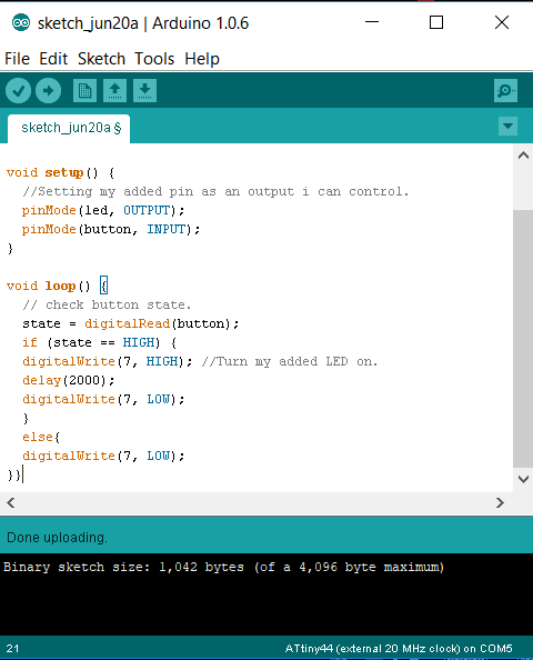
I managed to melt the route on my week 7 board so I made a new board and re-soldered it with my improved skills and managed to make it work on the first try. Burnt the bootloader and uploaded another code I wrote myself for the LED to turn on for 2 seconds when the button is pressed.
Here is a video of it working.
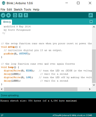
Next, I researched a bit about C++ and wrote my code for my LED to blink.
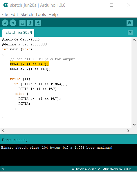
Here is a video of the board working.
Finally, I dug a bit deeper and made my button turn on the LED with C++ code uploaded on Arduino IDE.
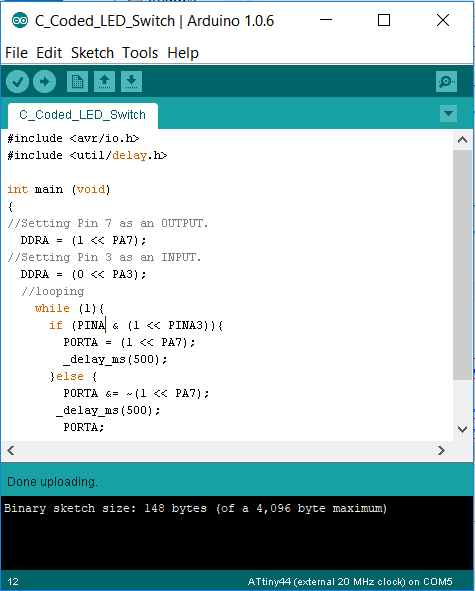
Here is a video of my board working.
Download the source code from the link below:
Hello World Board Code: Arduino (.ino file)
C++ Blink for Hello World: Arduino (.ino file)
C++ Code Button + Switch: Arduino (.ino file)