This weeks assignment was redrawing (with our original touch), milling and soldering a "echo hello-world board". I've been dealing with 3D printers for years now, but electronics is a whole different story, first time designing a board so I got straight to it. I decided to use Eagle since I had already used it for week 5: electronic production. First I downloaded the next images of the board.
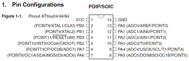
Having a clear idea of what I was attempting helped get my gears in motion. Before I started designing the Schematics on Eagle I took a look at the datasheet for the ATtiny44.
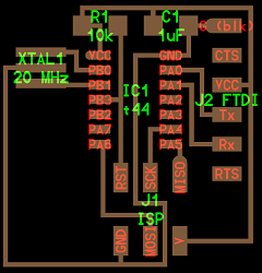
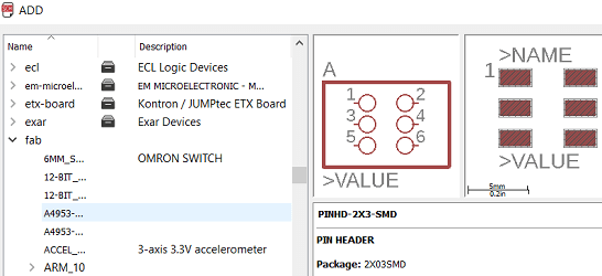
To design the schematic in Eagle you have to add all the components necesary and after connect them (as shown in the first image which was used as reference to create the schematic). In order to do this we use the add button for each component as shown in the next picture.
Once all the components are added I started connecting the ones shown in the example image.
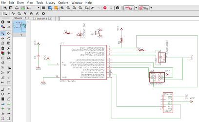
As you can see I hadn't connected the LED and button yet. Once they were connected the schematic looked like this.
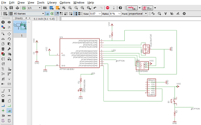
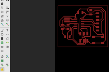
While connecting everything I discovered that cables with the same name dont need to be connected visualy in the software as it assumes they are connected making this process much simpler. Now that my schematic was ready I proceeded to generate the board by selecting File>Switch to Board. This is how it looked.
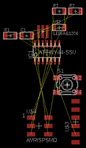
The yellow lines indicate which connections are necesary. I tested the autorouter but after some attempts I decided to design the board myself step by step. The ratsnest command helps alot as it generates the optimized yellow routes as you move the components around(thoroughly recommend using it).
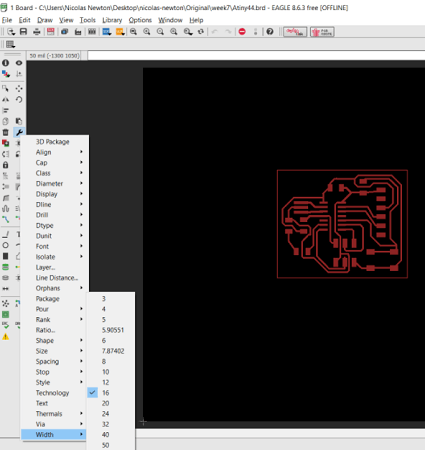
Before I started designing I had to decide my trace width which I found in the tool above (change(wrench icon)>width>select your width).
I opted for 24 on the paths that had enough space and reduced it to 16 for the paths that had too little space for a 24.
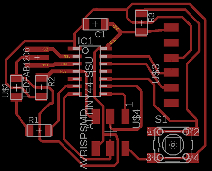
It took me about an hour but eventually I had a design that worked.
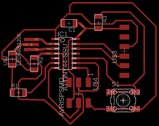
Once my board was finished I checked for errors with the DRC tool (Caution triangle icon on the bottom left). Nothing reported back so I assumed my board was OK.
Finally I moved components a bit to make my board more efficient regarding area, it didnt change much but I felt better about it.
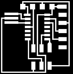
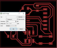
Once I had my finished design I had to pass it through Fabmodules to generate my G-Code so I saved my design as a monochrome .png file.
First I imported my monochrome into Fabmodules. Next I chose the output option: G-Code and the Process option: PCB 1/64.
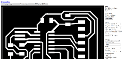
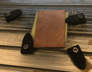
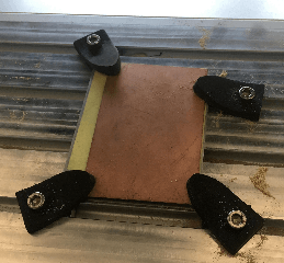
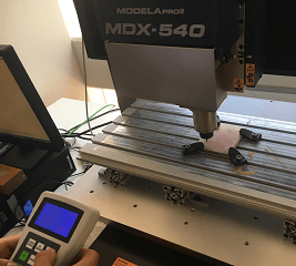
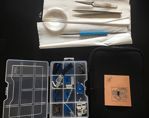
Finally, I modified the spindle speed to make sure our router would cut the path properly and I generated my G-Code file. I then proceeded to mill my Hello_World board. First, we had to set up the plate we were to mill. It proved harder than it looked.
Once its set you have to set up the zero for the Z axis by moving the tool with the controler and then lowering the tool until it touches the special tool to zero the Z axis(looks like a holeless wheel).
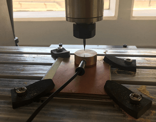
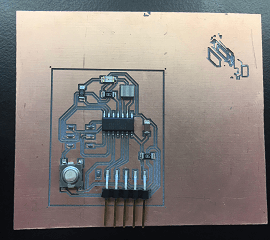
Finally, you start milling your PCB.
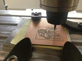
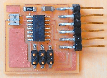
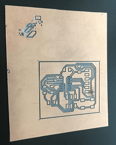
This was the PCB after milling.
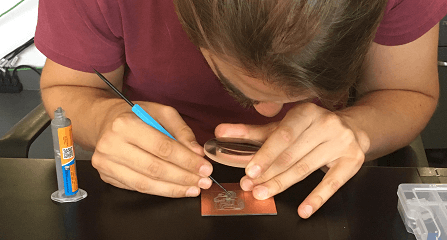
It was time to start soldering with flux! At first Flux can be tricky but after some practice it becomes your best friend when soldering this type of PCB.
Slow and steady my PCB started looking more like a Hello_World PCB.
Some more soldering...
And voila!!!
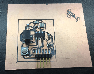
So in total I added a power LED and a switch button with a limiting resistor each. Limiting resistors are used in LED lights to prevent them from burning out from high voltages. The main reason I used the resistors was to keep the current at the characteristic(recommended) forward current. Regarding the switch/button I used the resistor to prevent any floating values from returning to my microcontroller from it. Regarding how I connected my button I ran the VCC route through 2 of its legs and a gnd route over the other 2 using pin #4(arduino pinout on datasheet).
Download the original files from the links below:
Modified Hello World Schematic: Eagle (.sch file)
Modified Hello World Board: Eagle (.brd file)
Modified Hello World G-Code: Eagle (.nc file)