Wheek 14: Networking and Communications
Networking Hello Serial Buss
This week I used the hello world board example to connect several boards together
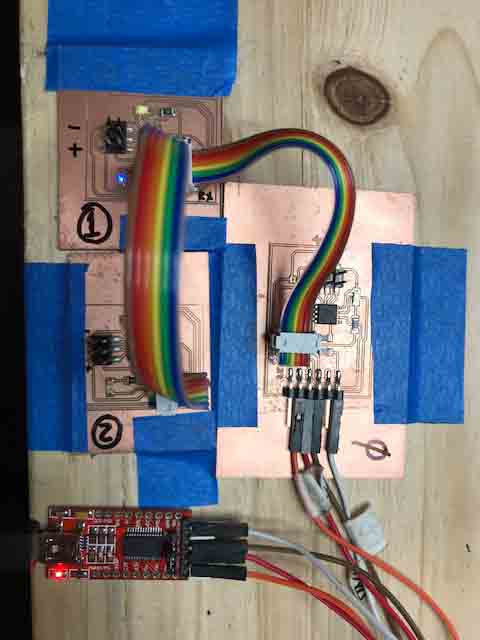
on a network using the serial bus protocol. The bridge is connected to a computer with FTDI.
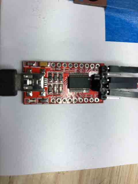
Fig 1. FTDI to comunicate the boards to the computer.
All the designs of the boards were once again made using the EAGLE software. All the boards have one led to indicate that tey’re being energized.
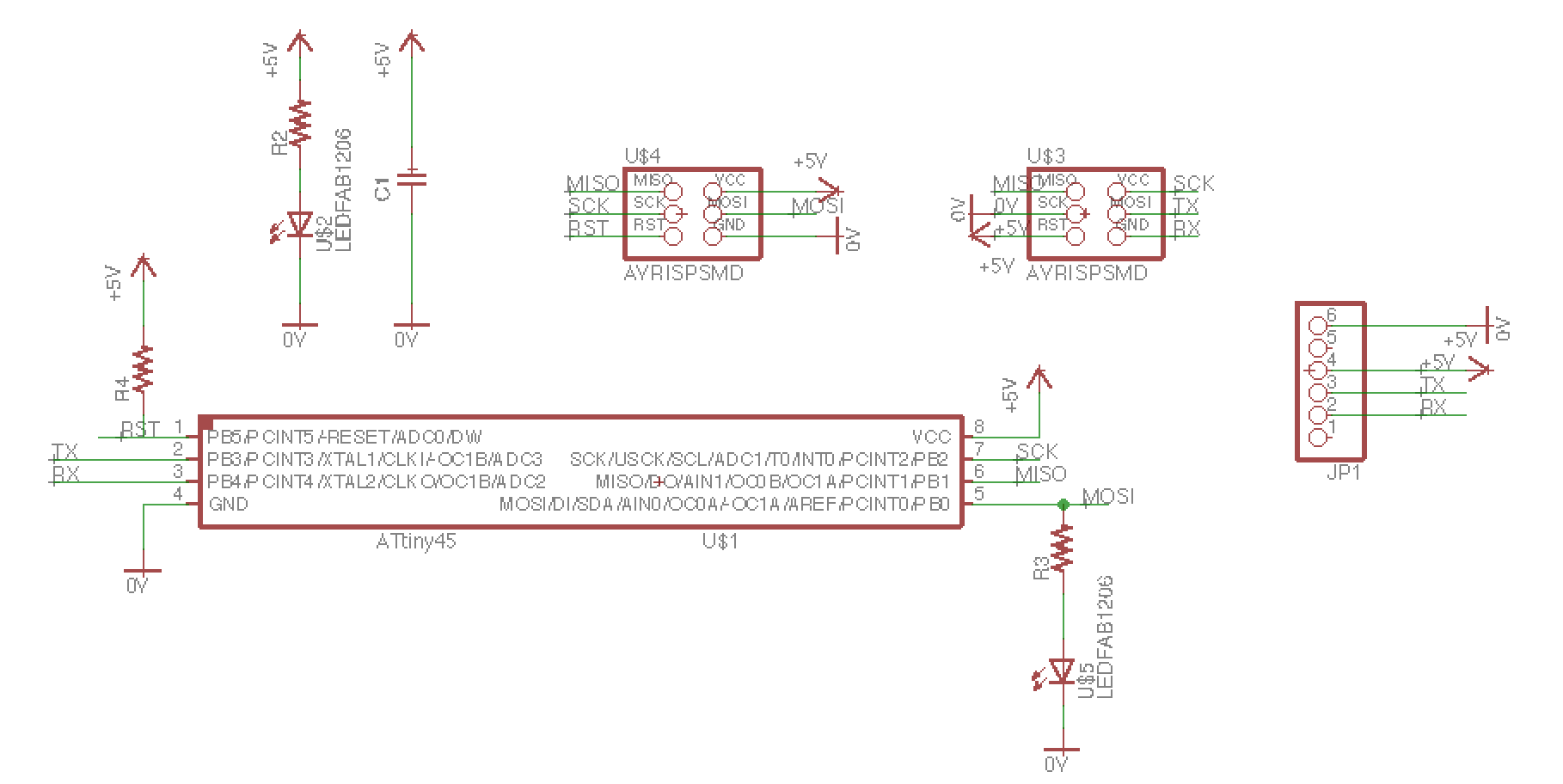
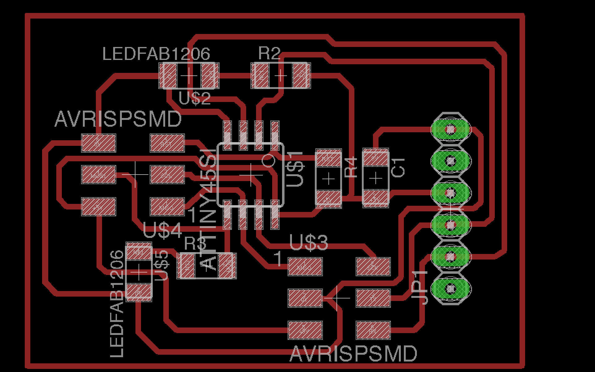
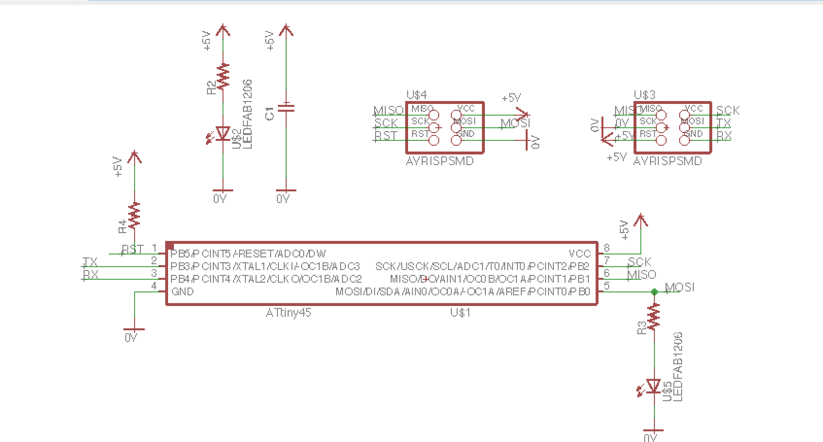
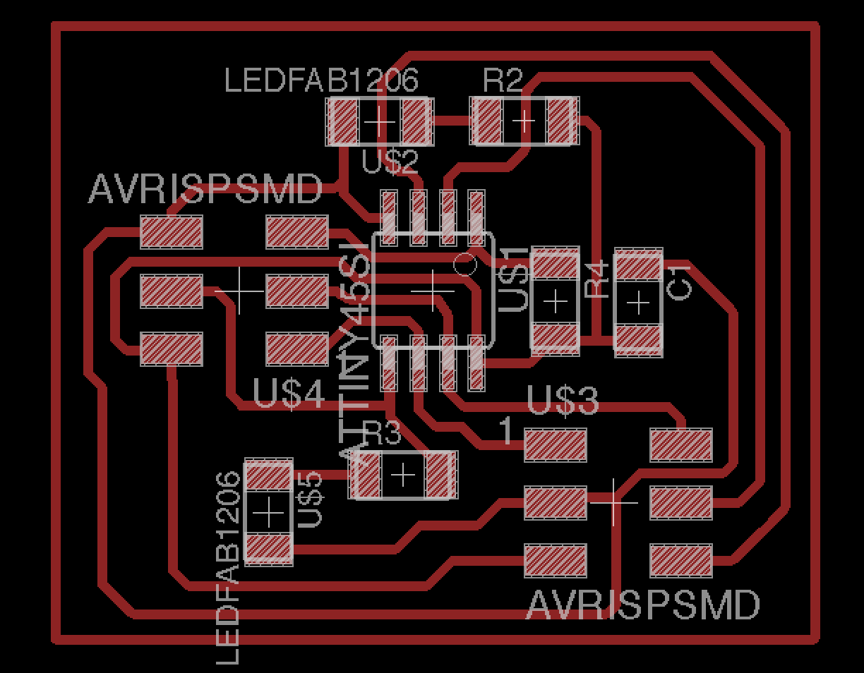
Fig 5. The node board on EAGLE.
The bridge and nodes will have an attiny45 embedded.
The datasheet shows on this link:
http://www.mouser.com/ds/2/268/Atmel-2586-AVR-8-bit-Microcontroller-ATtiny25-ATti-1065586.pdf
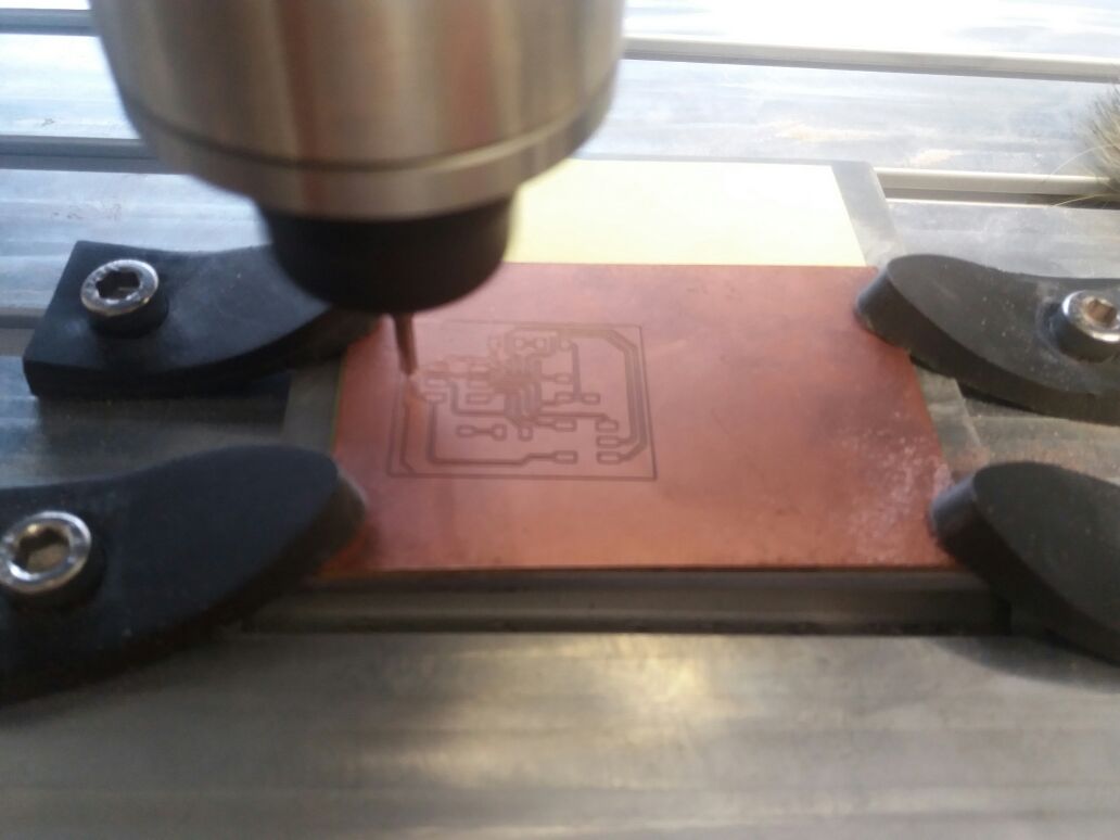
Fig 6.The boards made with modela mdx 540 by Roland.
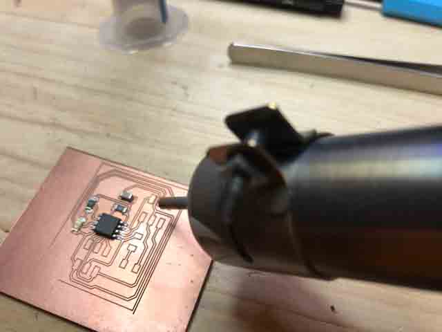
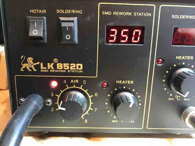
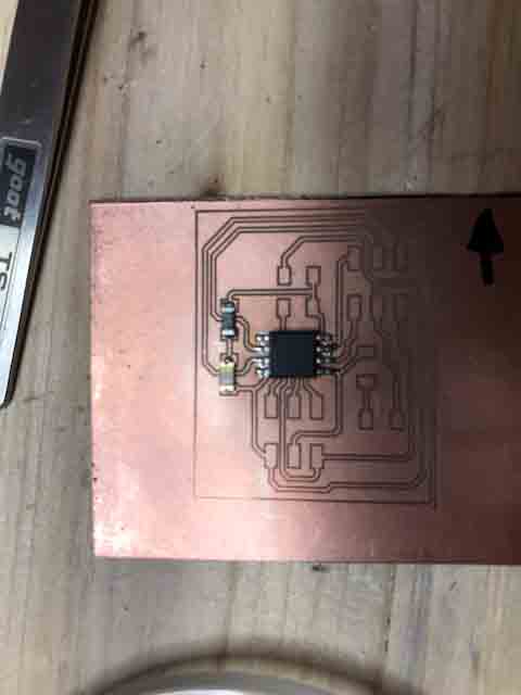
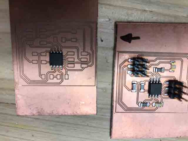
Fig 10. Two nodes finished.
The firs step was to burn the boolader on the respective boards: one brigde and two nodes.
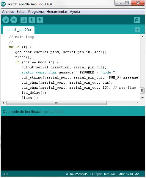
Fig 11. Done burning bootloader.
Get the board files and code:
http://academy.cba.mit.edu/classes/networking_communications/index.html
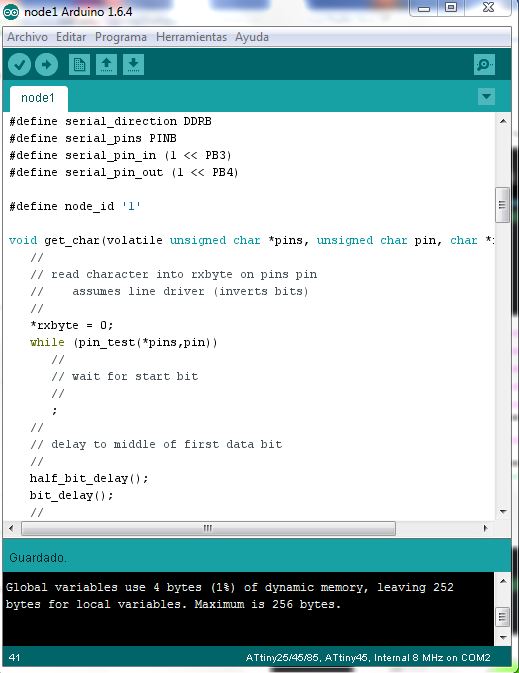
The Link code with Neil’s code:
http://academy.cba.mit.edu/classes/networking_communications/bus/hello.bus.45.c
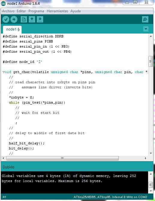
I made two nodes and one brigde. I modified the “c” code; for example on the brigde de id number was “0” (# define node_id “0”) and the nodes “1” (# define node_id “1”) and “2” (# define node_id “2”).
**VIDEO**
This video shows the the led on the red RS-232, change the frecuency and regulated the intency of leds.
Right mouse button to play video
**VIDEO**
This video shows the blink on the node 1.
Right mouse button to play video
node board
node Schematic
bridge board
bridge Schematic
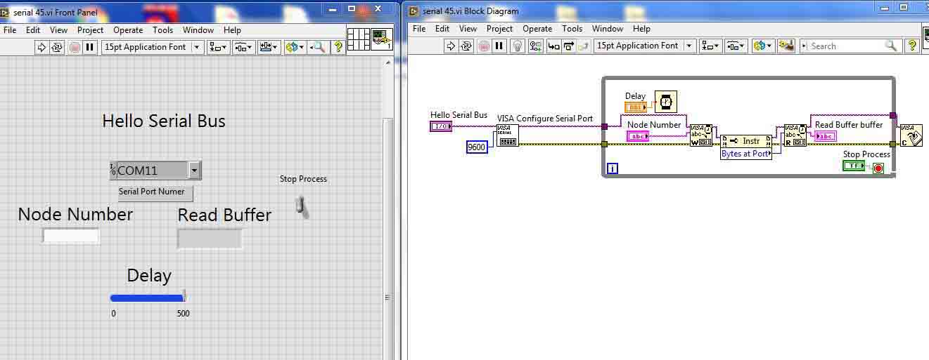
Labview program.