Wheek 13: Interface and application programming.
This week assignment was to make an interface program and connect it with an input or output device. i made a satschakit board as the controller board and link it to a Labview interface. The workflow was use the satchakit to read the an analog signal and show it in a graphic interface that was programmed using Labview. This signal will be used in the future as a robust control with PWM signal for the final project. I learned about this assigment, and used this link: For more information the following link:
http://fabacademy.org/archives/2015/doc/projects/fabkit-0.4.html
http://ww1.microchip.com/downloads/en/DeviceDoc/Atmel-42735-8-bit-AVR-Microcontroller-ATmega328-328P_Datasheet.pdf


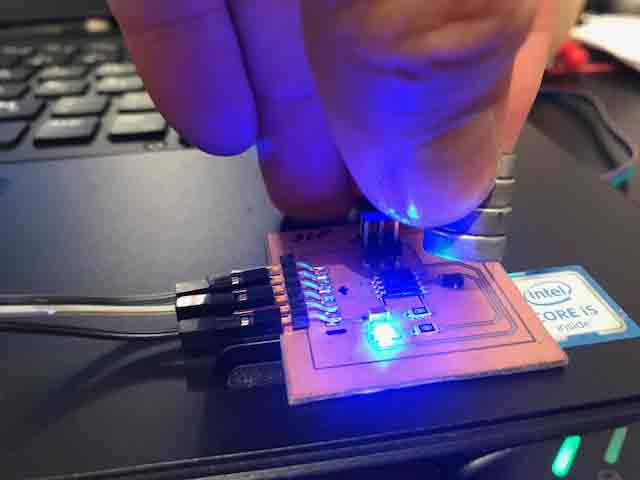
This time I made three boards due to some machining errors, wrong parameters and soldering mistakes. After all the problems were solved, the third board worked smoothly.


Pin 13: SCK
Pin 12: MISO
Pin 11: MOSI
RST, Positive and negative.

Fig 9. The Pin connections to satschakit.
Now I made an extension board for an input device. The temperature sensor LM 35 was chosen as the sensor. This link shows the Data sheet of this sensor.
https://www.mouser.com/ds/2/321/604-00011-LM34-Temperature-Sensor-Datasheet-337154.pdf


The next step was to make the interface in Labview, I learned to use this program and used an example that I found on the web. The goal is to read the signal from the Arduino. I used FTDI to conect Arduino to labview via RS232. The data flows from the sensor to Arduino and to the graphic interface from Labview.

Link to Labview:
http://www.ni.com/es-cr/shop/labview.html
Link to use Labview for serial comunication:
http://www.ni.com/white-paper/7907/es/


Fig 18. Control Panel functioning with the Satschakit and Labview.
**VIDEO**
This video Shows the Control pannel working with Arduino and Laview together.
Right mouse button to play video
Now I tried to make a microcontroller board myself adding an input device and connect it with another tool I wanted to give a try. This time I made a hall effect microcontroller board and connect it with a graphic Interface I made using Processing.

The link:
http://academy.cba.mit.edu/classes/input_devices/mag/hello.mag.45.cad


Fig 21. This square change when the magnet is next to hall effect sensor as an activation indicator. The black colour shows no presence of any magnet. and the grey colour when it senses the presence of a magnet.
**VIDEO**
Showing the efect from magnet on the hall efect sensor and the processing interface.
Right mouse button to play video
Processing Program
Labview program.
Arduino program.