Embedded Programing
First steep I need to read data sheet about the ATtiny 44. Given the good example and tutorials online. I used tutorial give this link:
http://fab.cba.mit.edu/classes/863.15/doc/tutorials/programming/Simple_examples/c_prog_examples.html
The ATtiny44 datasheet following link:
http://fab.cba.mit.edu/classes/863.09/people/ryan/week5/ATtiny44%20Data%20Sheet.pdf
This week assignment was to program a microcontroller board with a stable programming environment. The idea was to use as many environments and languages as possible. In this case I worked with:
•Arduino IDE.
• Flow code 6.
• Atmel Studio 6.
Arduino Ide
The first ide to try was the well know Arduino. In this case I needed to install the 1.6.4 version this is the best choice, I learned that this version works better with the attiny44 MCU since I already had the board functioning. I found this information in this PAGE: http://highlowtech.org/?p=1695 For more information the following link:
http://highlowtech.org/?p=1695
Paste the following URL into the field (use a comma to separate it from any URLs you’ve already added): https://raw.githubusercontent.com/damellis/attiny/ide-1.6.x-boards-manager/package_damellis_attiny_index.json
Fig 1. Additional Board manager URLs Next step was to go to tools and select board’s manager Fig 2. Add external board. Nand then select ATtiny by Davis A. Mellis. Fig 3. Attiny complements. Now, having intalled this new library, select the new processor, in this case select the board: ATtiny 24/44/84, processor: Attiny 44 and the clock: 20 MHz and port:COM1 Fig 4 selecting the right processor. At this point, we need to burn the bootloader on the ATtiny to allow it to be programmable with the Arduino IDE. Now the board is ready to accept information from this IDE . I prepared 2 programs to test the board with ATtiny 44. The first program was a simple blink. The second program was to turn on an LED when pushing a button. To keep in mind the correct pinout, I analyzed the datasheet of the Attiny44 MCU. Fig 5. Data sheet of the ATtiny 44.
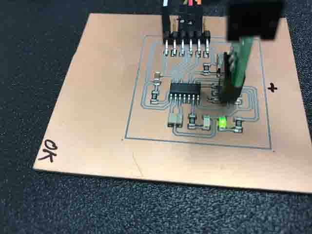
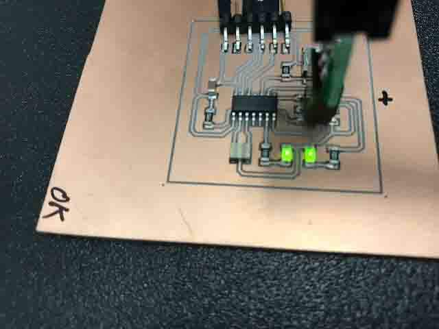
State Initial on ATtiny 44. The Led on indicated the board is ready.
The LED output is connected to pin 7 on Arduino and pin 6 (PA7) on the Attiny. The input on Arduino is 3 and 10 (PA3) on the ATtiny. This is the first program test on Arduino Ide 1.6.4.
Led program on Ide Arduino. Led program on Ide Arduino. The second program with one input button and an LED.
Swicht and Led program.
Video Led-Swicht.
(Right mouse button to play video)
Flow Code 6
The next IDE I used was Flowcode 6. This is the best choose when you need fast programing. This structure is based on flow diagrams. In order to program the Led on flow code, I need to specify the output port (pin) and the bitrate (value). In my ATtiny board the output port is 7. Fig 6. Configuration of the port or pin 7. Now I downloaded the program on flowcode 6 and then pushed to the ATiny 44. Fig 7. the program was successfully uploaded. Then I wrote the second program with the switch button and an LED on flowcode 6. I configured the input port to 3 (pin 3) and output port to 7 (pin7). The program makes a decision to know whether the switch is pressed or not. The program runs on a while loop. Fig 8.Program on Flowcode 6 running on a while loop. The program was successfully uploaded on the ATtiny 44.
Fig 9. Successfully uploaded the program on ATtiny 44.
Atmel Studio 6
Now I give Atmel Studio 6 a try. This is the professional IDE for any type of Atmel chips. The software is free with the basic tools. To start to use this software go to FILE, NEW and select Project
Fig 10. Environment of ATMEL STUDIO 6. This display shows 4 templates. Select executable Project, this is the best choice to program ATtiny 44 because it allows to program in C++. Fig 11. The environment choice: Executable Project.. Select the family chip Atmel and then select ATtiny 44 on Atmel Studio. Fig 12. select the family board. This script show the first program on Atmel Studio. I Needed to put two libraries first:
Fig 16. options before uploading the program on chip. When the program uploads on chip some message will appear showing either if the upload was successful or if there have been some problems when uploading the program. In this case everything went all right.
Fig 17. Program uploaded successfully. The second program was the Led-Switch. The following script shows extra line different from the first program. One again I needed to define the frequency of the crystal.
Fig 18. The Led-Switch program on Atmel Studio 6. And finally, the program was once again uploaded successfully.
Fig 19. Led-switch program uploaded the chip.
Files with different IDE
Need to download Arduino Ide, Files on extension .ino
Blink-Arduino
Blink with Button
Download files on extension .rar
On Atmel Studio 6, Files on extension .rar
Atmel syudio Led.
Atmel syudio Led-BUTTON.
On Flow Code 6, Files on extension .rar
Led on Flowcode 6.
Led with button on Flowcode 6.


