Wheek 4:Computer Controlled
Cutting
In this week, we have learned how to use the computer cutting machinery, laser cutter and vinyl cutter.
Laser Cutting.
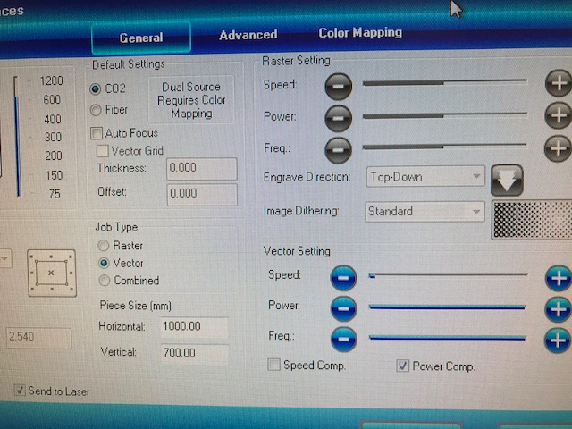
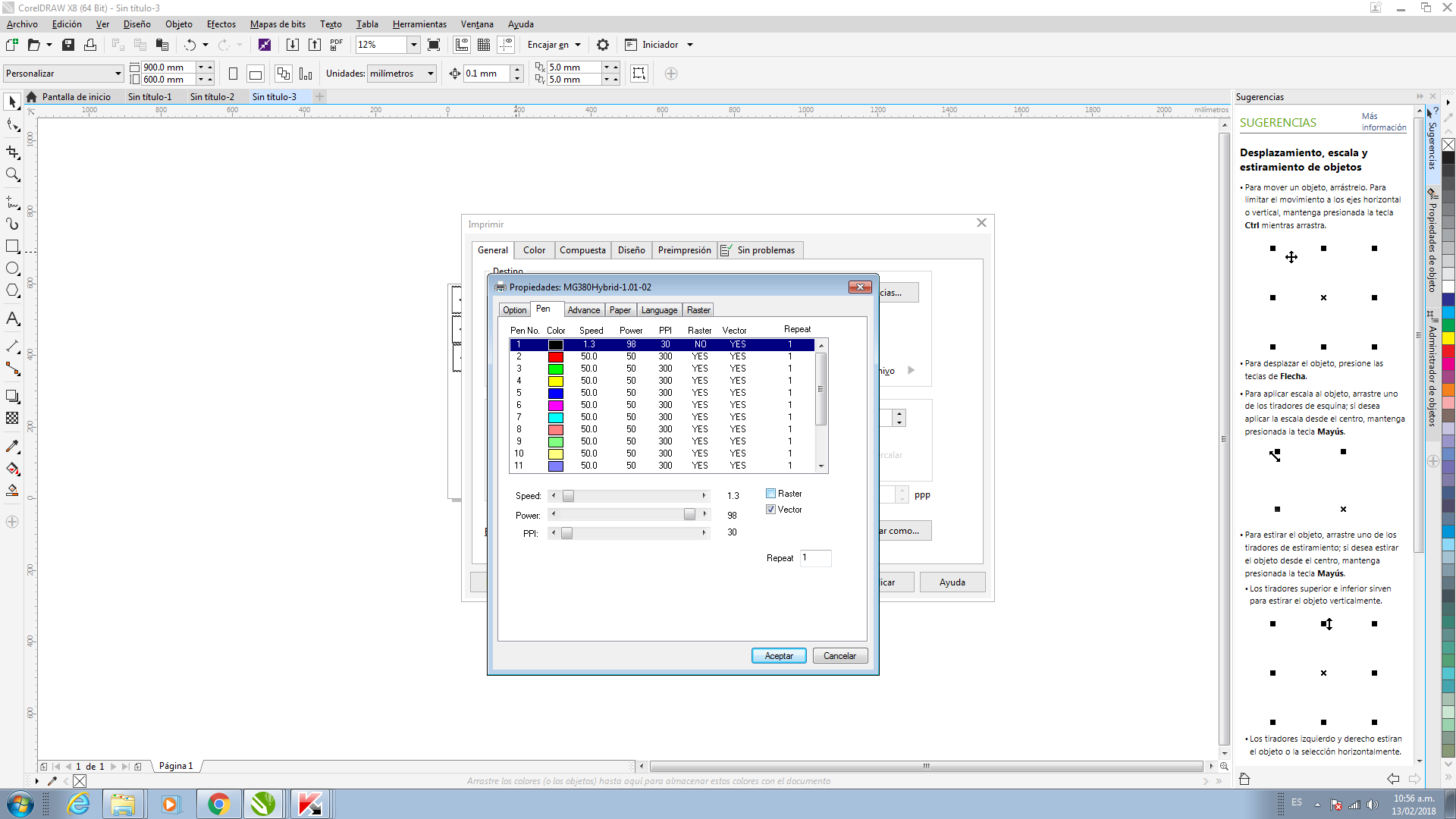
The laser cutter uses Corel Draw to input cutting parameters, and imports the image from inventor. The extensions used were dxf from Inventor and import to Corel. Provided all these tools, it was very hard to decide which one would suit me the best. I used Inventor from Autodesk on 2D or 3D I generated the 3D sheets and exported the file.
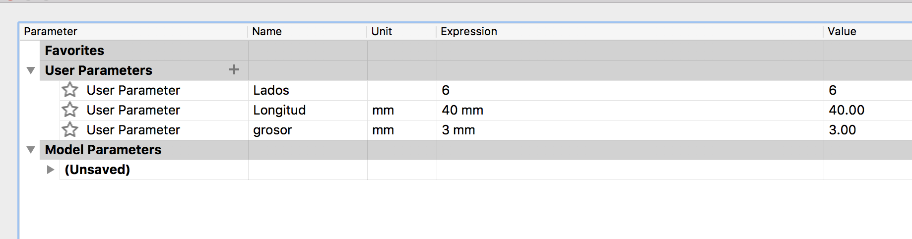
Parametric Design.
During thid week I designed a simple support for my phone with press fit.For the process I used fusion 360 with parametric design.
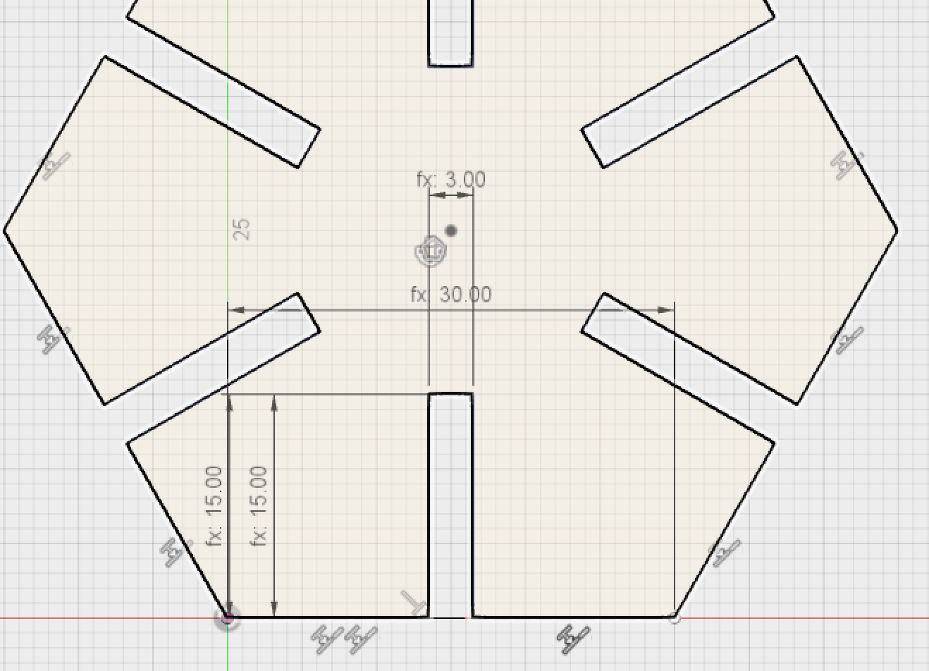
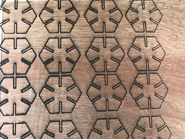
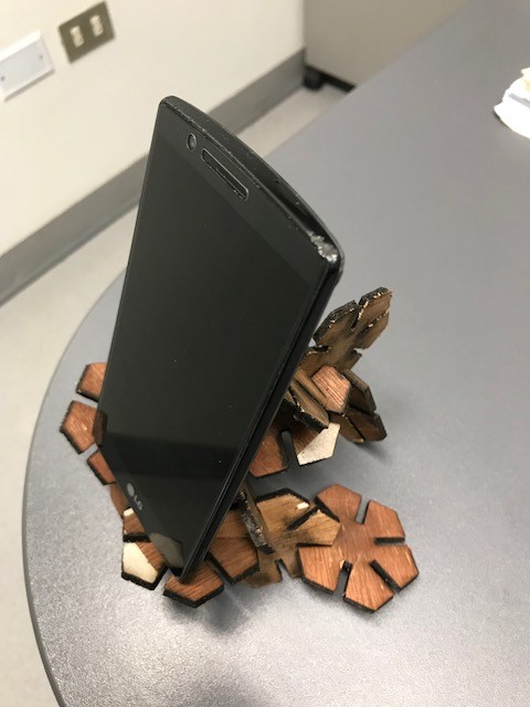
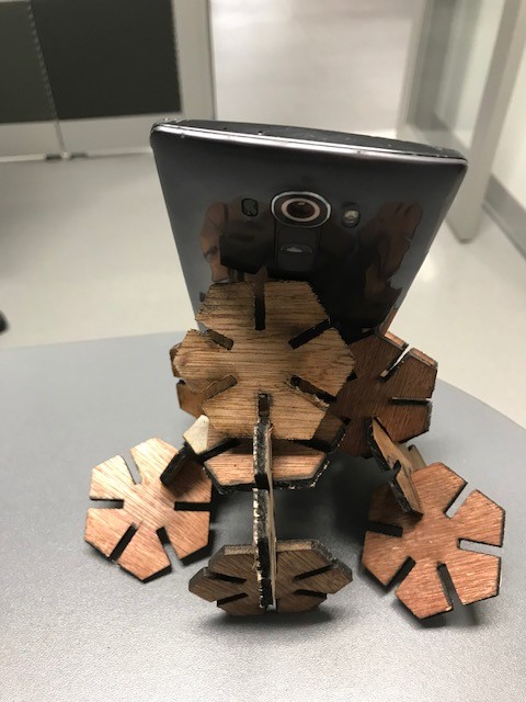
The Design.
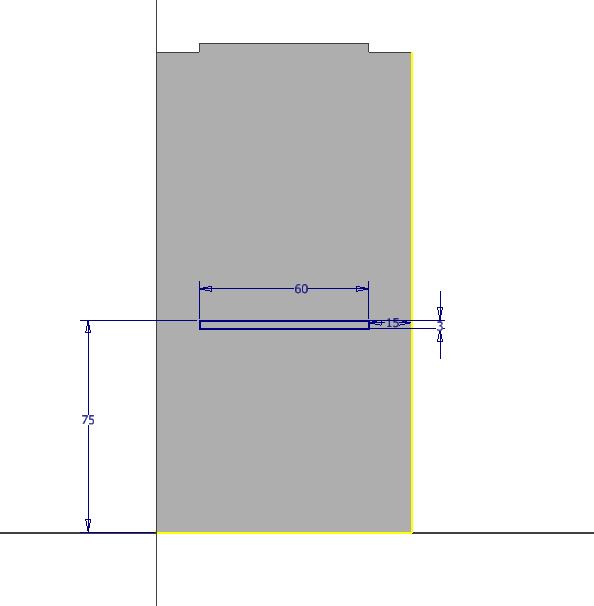
In the assembly model show that.

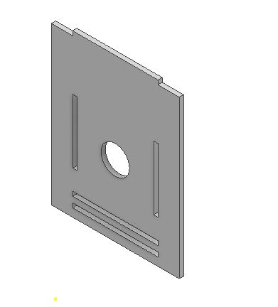
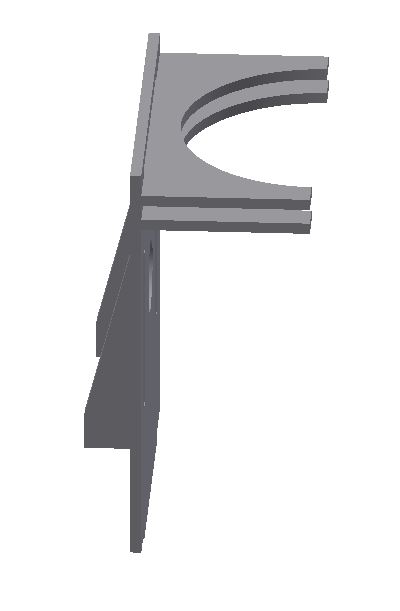
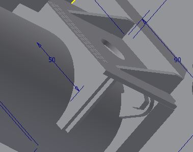
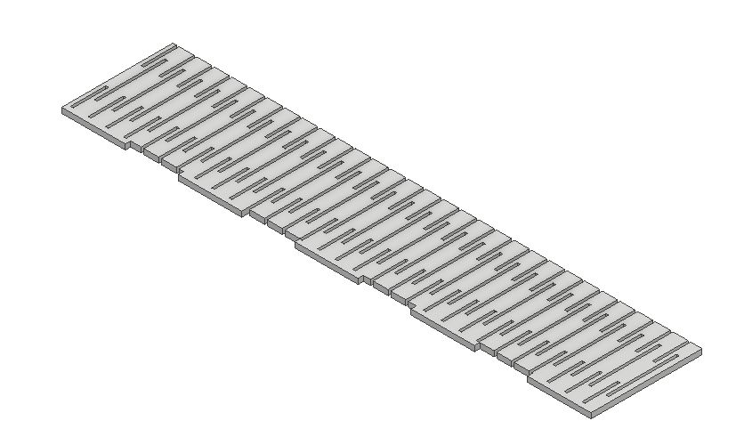
The other part of the assignment with the laser machine consists in designing the flexible guard on Inventor.
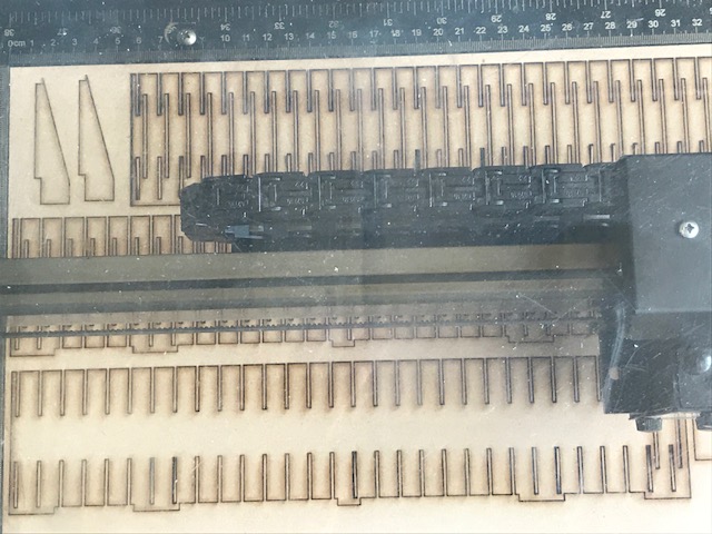
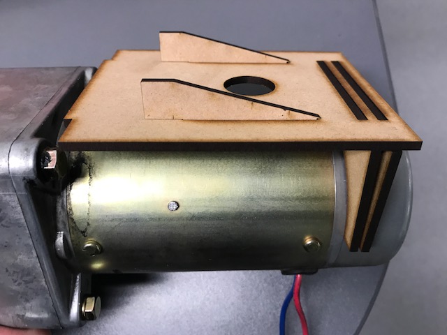
The next pictures show the assembled flexible guard. This is used for the lemon hopper.
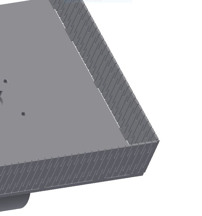
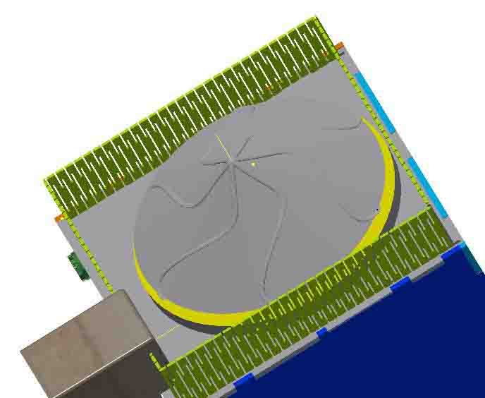
Fig 25. Flexible guard in the squeeze machine .
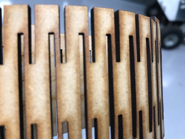
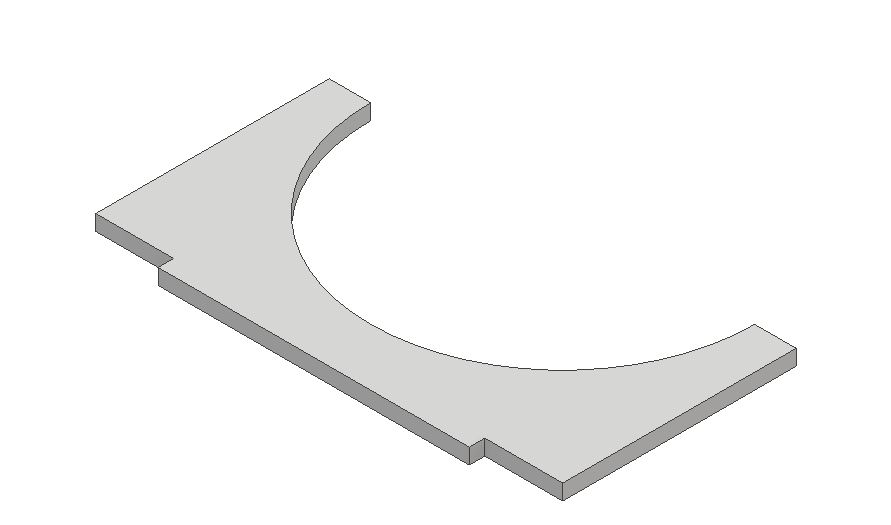
Fig 26 Example of guard flexible.
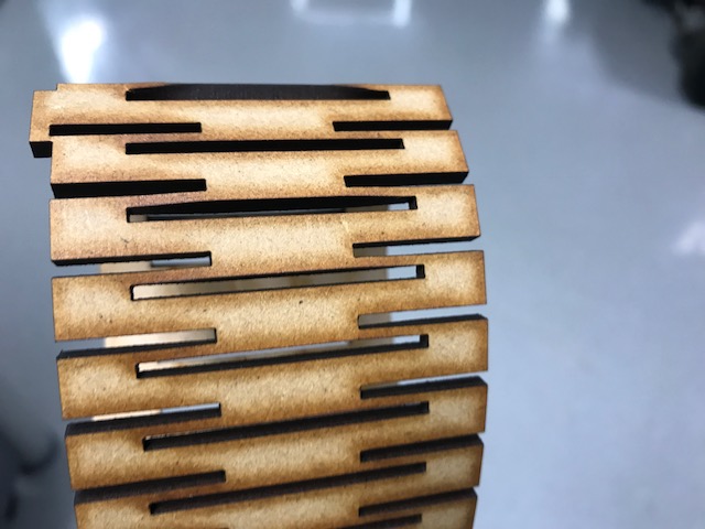
Fig 27. Other view, Example flexible guard.
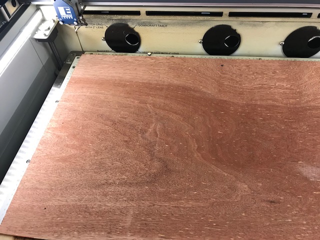
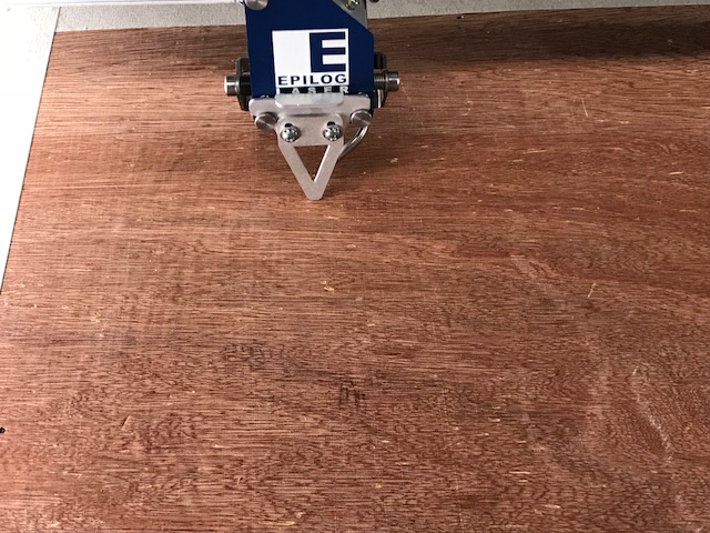
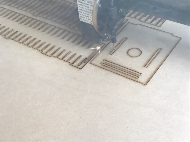
The kerf in my asigment was 0.2mm. I used plywwod.
Link for the kerf:
http://www.cutlasercut.com/resources/tips-and-advice/what-is-laser-kerf
Vynil Cutting.
The second part of the assignment for this week was Vynil Cutting. I found a picture that seemed easy to vectorize. In this case I worked with Corel Draw.

Fig 28. Picture vector from the internet.
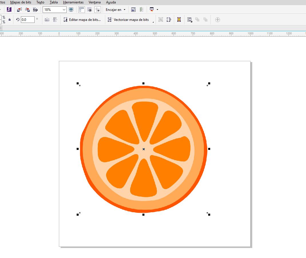
Fig 29. Sample on Corel Draw.
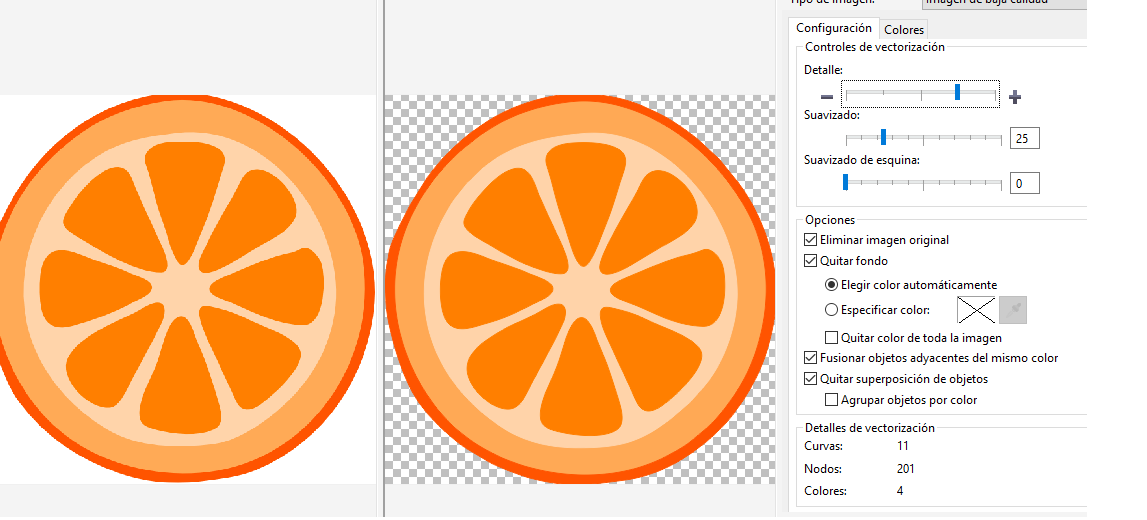
Fig 30 Vectorizing the image on Corel Draw.
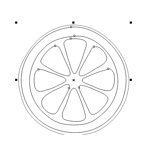
Fig 31. Image vectorized.
Ready to be sent.
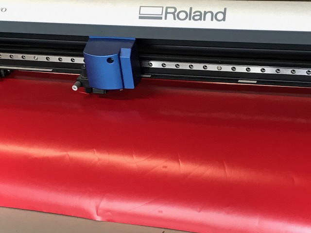
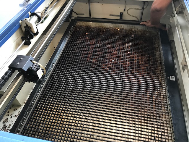
Fig 32. Machine cutter.
Finally we obtain sticker.
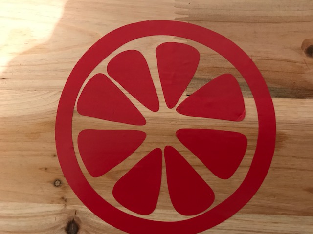
Fig 33. Sticker obtain finally.

Fig 34. Final Cut.
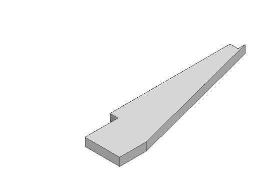
Ribs
Safe guard.
Plate
Support part.
New archive pressfit.