Wheek 3: Computer-Aided Desing
2D Desing
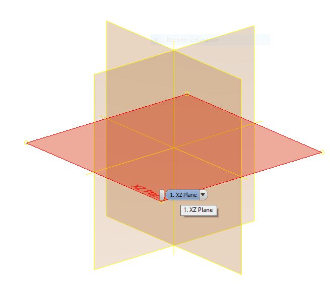
In this week, I used Autodesk Inventor and Solidworks for 2D design because I find it easier this way to desing. When using the parametric software the first thing to do is selecting the plane on which we’ll draw the 2D sketch.
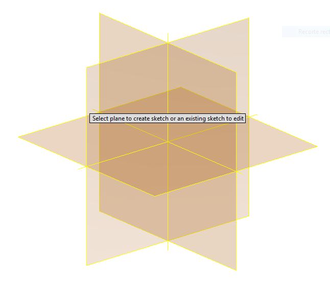
And select the working plane.
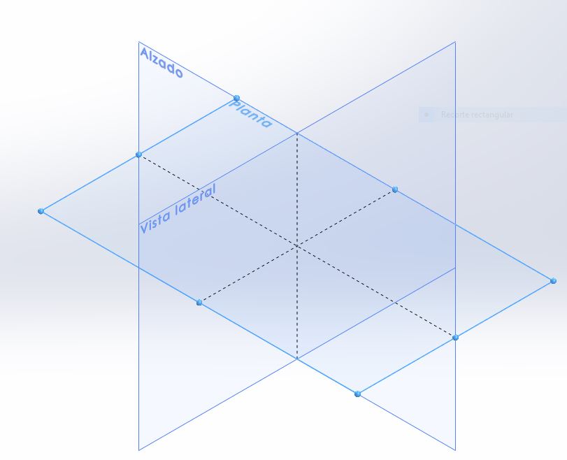
Solidworks works in a similar way
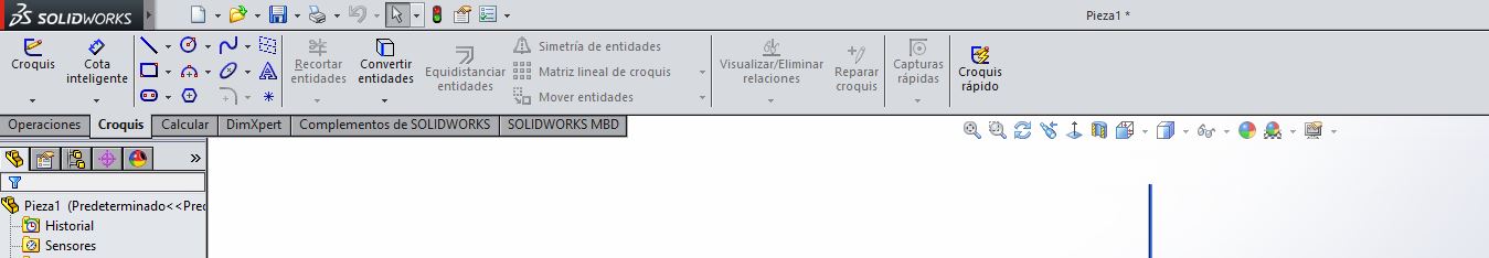
The sketching tools for 2D design is show in the picture below:
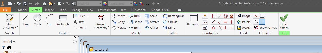
And the tools on SolidWorks are displayed in a similar way.
The most important thing when using this software is parametric design. Put dimensions in all the drawings generated. The dimensions you wish will be set immediately after placing the first line.
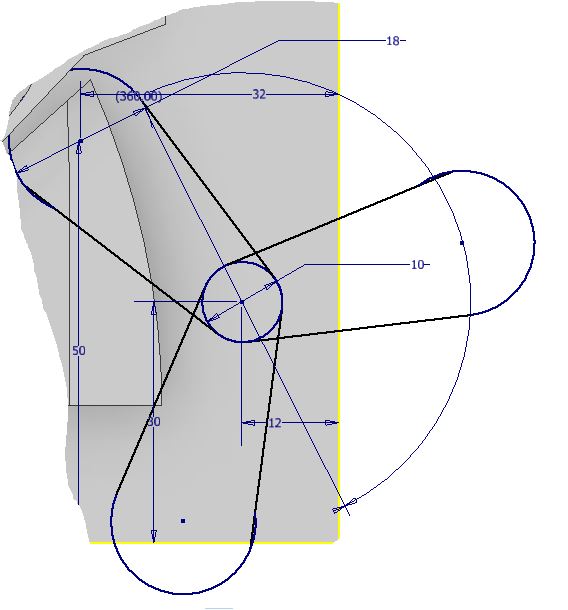
The workflow for the sketching of this piece was first, draw one arm (the circle at the middle and a wing that consists of 2 tangent lines and a external circle), and then use the tool “circular pattern” having the midpoint of the circle at the middle and rotate 360 degrees. For the integration of all pieces we have to have some considerations such as the distance between pieces and the offset from the piece to the case. The important thing in designing is to imagine the integration of all pieces in real life. To make the 3D profile we just need to go to the “Features” panel and select “Extrude”.
3D Design
The power of this software relies on the integration, simulation and articulation of all pieces together as in real life. We just model the different pieces and integrate them on an assembly. This allows you to simulate the behavior of the system in a whole as a real life machine. My all time favourite software was Autodesk Inventor. I got a free license as professor of the University.
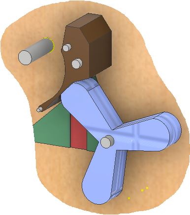
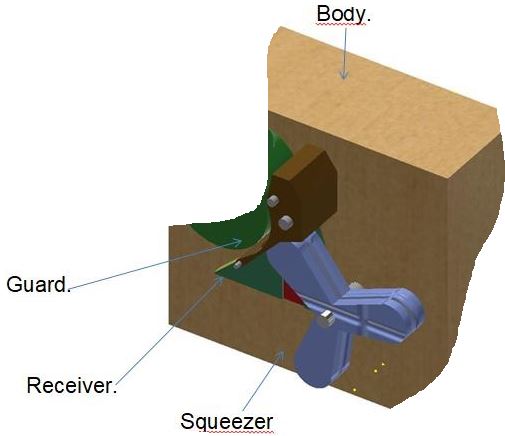
In this draw shows the integration of the main parts of the squeezer machine that will later become my final project.
For this assignment we are supposed to try as many design software as possible, so I made some models using two other 3D modeling software: Solidworks and Fusion360. Now I worked with the drum piece for the squeezer machine on Solidworks and finally, created a new surface using fusion 360. Format compatibility now is not a major problem, Most 3D software can output compatible formats. This time I exported all designs using the IGES format (*.igs). This is a very simple way to carry models from one software to another.
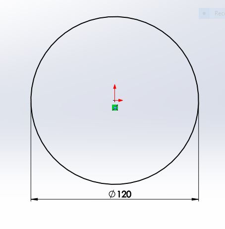
Fig9. Draw a circle with in the selected plane.
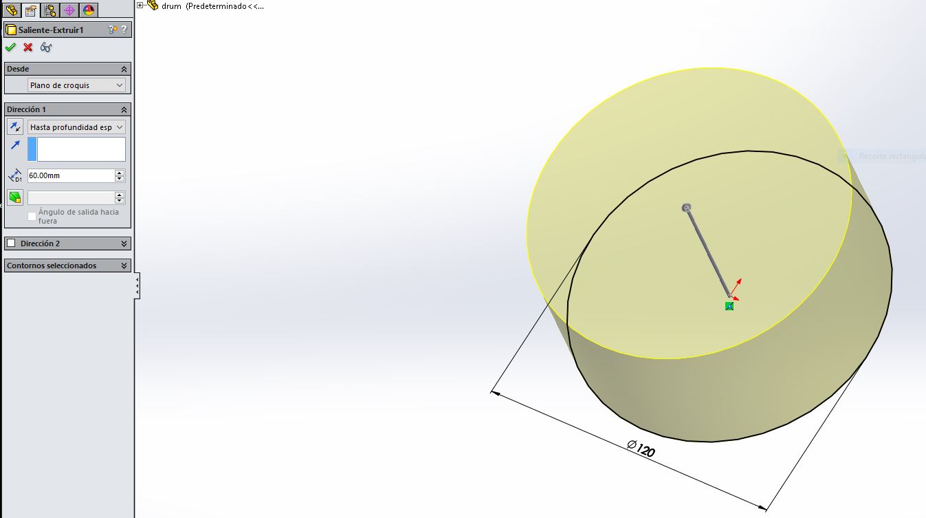
Fig10. Extruded the circle 60mm.
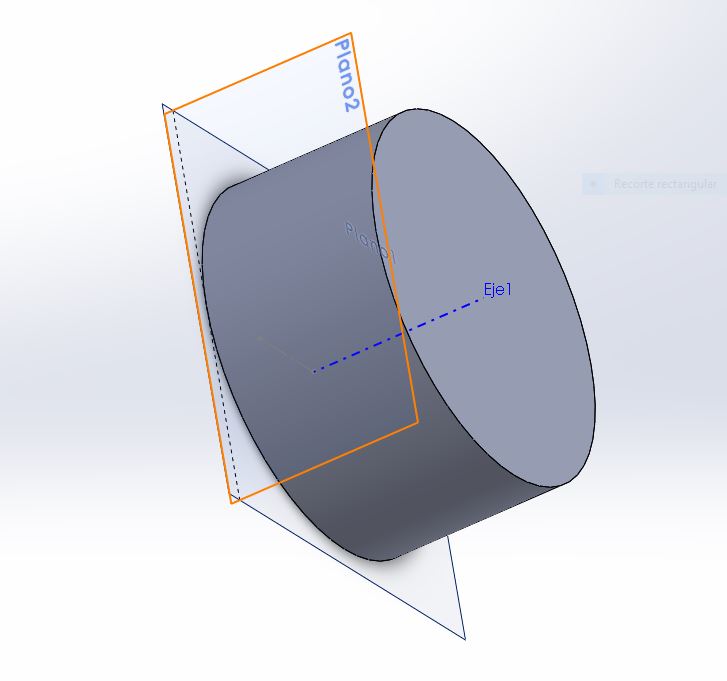
Fig11. Created a new axis a plane tangent to surface.
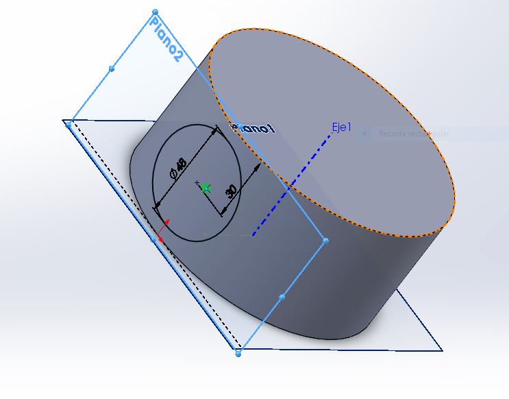
Fig12. Created a new circle with 48 mm of diameter and 30 mm distance from the edge to the center of the circle.
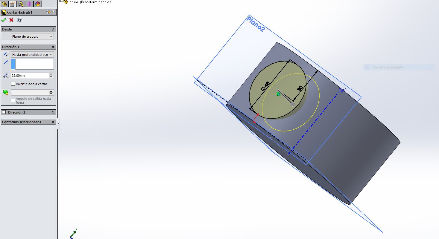
Fig13. extruded a hole with 22 mm depth.
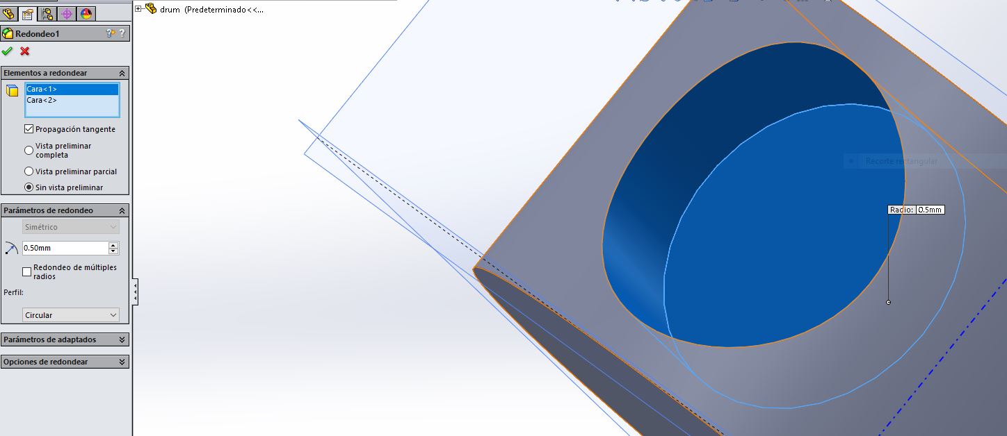
Fig14.Next used fillet of 0.5 mm for the edges.
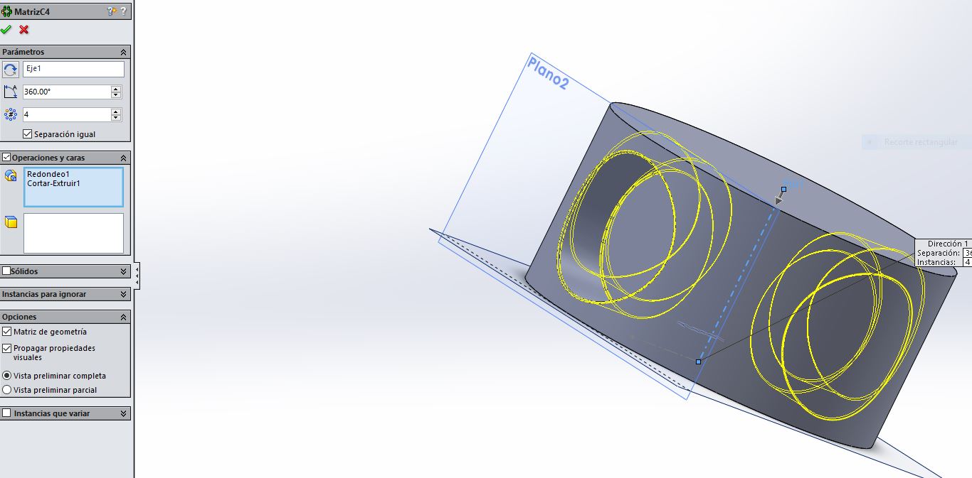
Fig15.Copy this feature 4 times with array matrix.
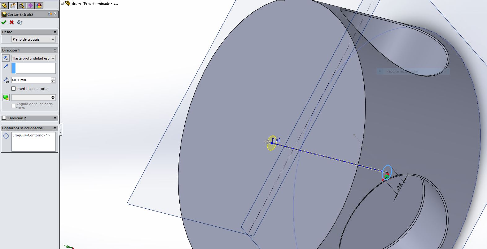
Fig16.now, I created the hole for the axis of the DC motor.
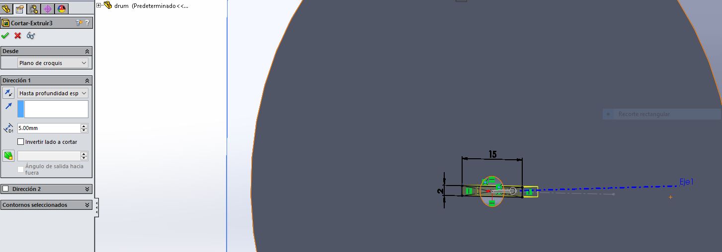
Fig17. This part clips on the axis of the propeller.
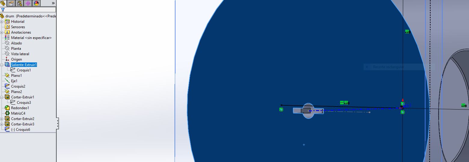
Fig18. Finally, made the connection part for the axis.
Now I used Fusion 360 software from Autodesk as Neil’s recommendation. I think this software is a great tool for drawing parametric. It’s a mix of Inventor and rhinoceros. This package treatment is very fast for modeling surfaces.
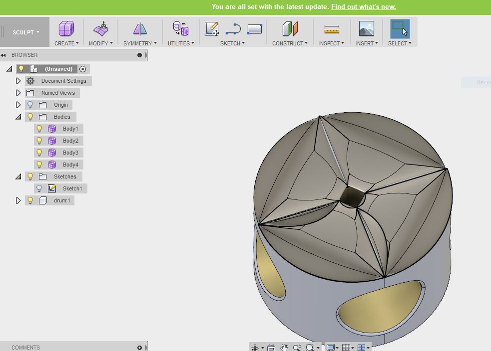
Fig19, This example shows the modification for the surface of the drum.
I plan to use all models I made in this week as parts of my final project. This, of course, can be changed in a future.
Part of proyect on Inventor.
Part of proyect on SolidWorks.
Part of proyect on Fusion_360.