The project development
The whole Lemon squeezer machine was modeled, component by component, using Inventor software. This is the first step in creating a functional machine because we can visualize a preview and makes changes if needed. This is initial assembly.
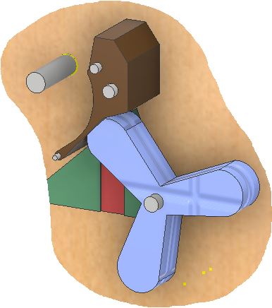
The drum and squeezer working together.
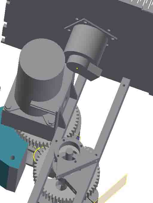
Here is the working of the gear set in the assembly.
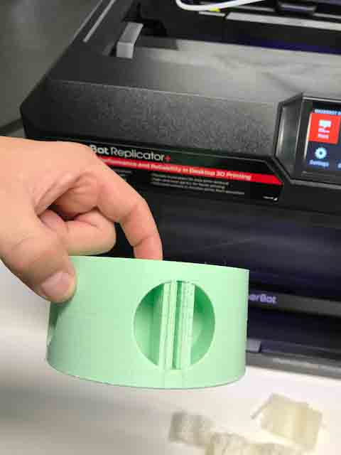
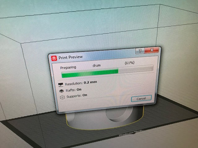
The component that will be the drum was 3D printed in a Makerbot 5th generation with PLA
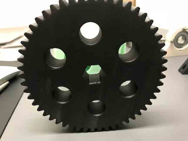
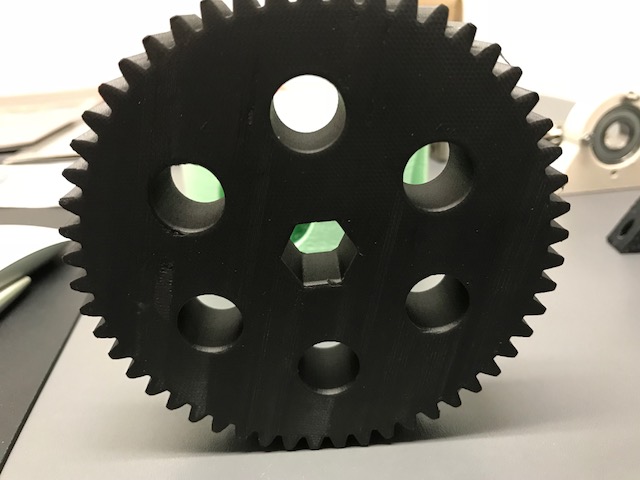
The gear was 3D printed on Carbon fiber with Makforged 3D printer due to the requiremet of a durable and resistant material. Markforged Onix Carbon fiber behaves like a 6061 alluminium alloy. “https://markforged.com/materials/”
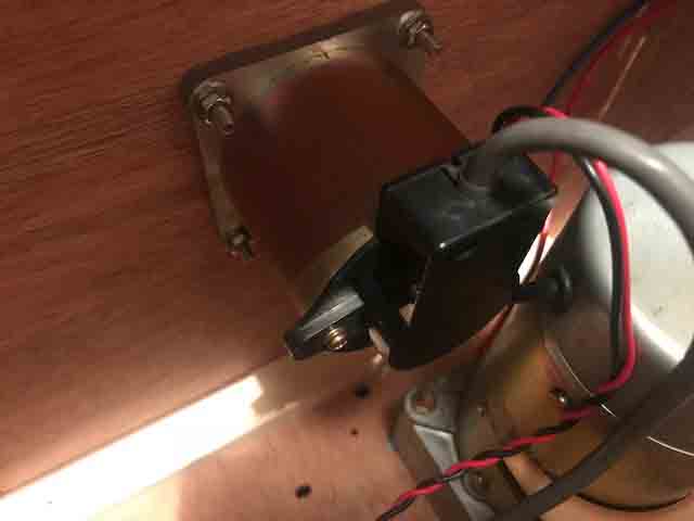
The main motor that will generate the movement of all the machine.
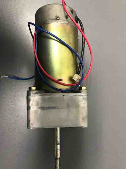
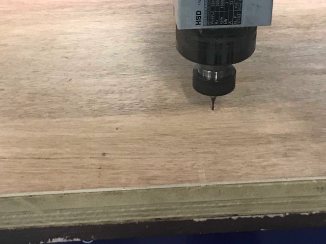
The support for the DC motor made at week 4
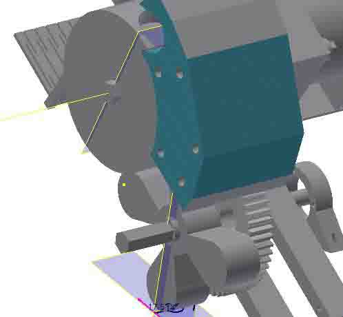
The bendable guard was made in week 4, also designed on Inventor.

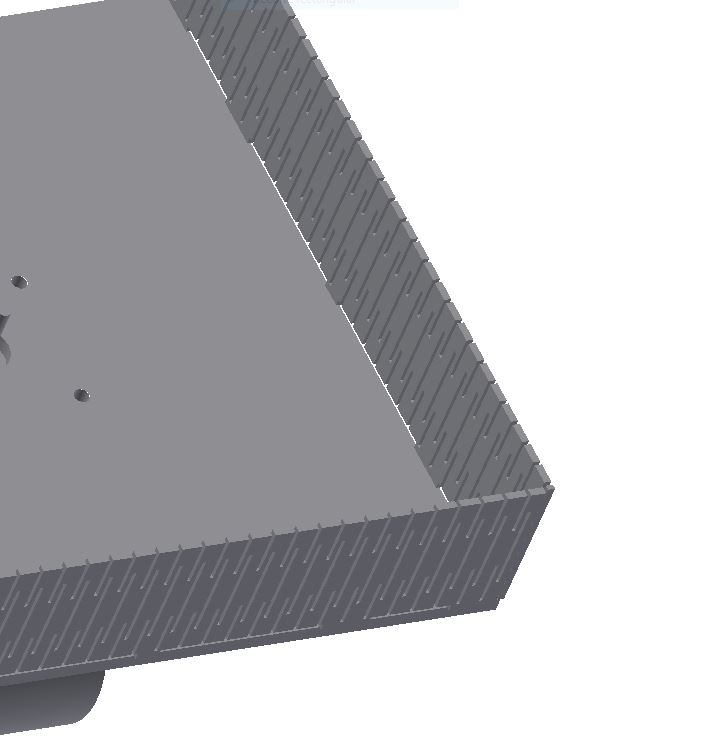
When laser cutting the mdf with this pattern we obtain a bendable structure known as kerf bending. This bendable structure will make part of the Lemon squeezer as the lemon hopper.
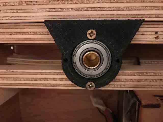
The piece with the ball bearing fitting perfectly. When I designed the piece on Autodesk inventor the external diameter of the hole was 35 mm but I put 35.4 mm instead. The 0.4 mm corresponds to hole on the extruder, made week 6.
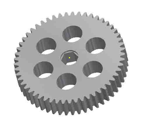
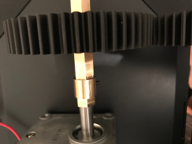
Transmission gear.
Up date week 10
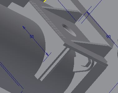
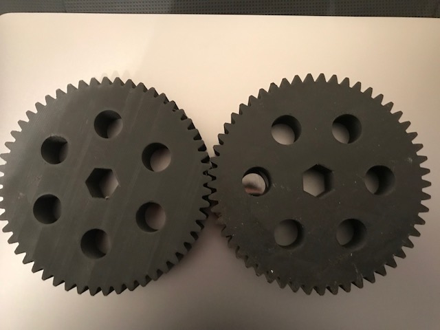
Two gears with the same dimensions are part of the gear set. The diameter is 110 mm , root diameter 106mm , height 20mm, teeth 53, module 2. This gear made on carbon and Kevlar.
Only one DC motor at 24v makes the system function, at 7.5 Amp. It moves the left hand of the drum from the squeezer and rotate the right hand.
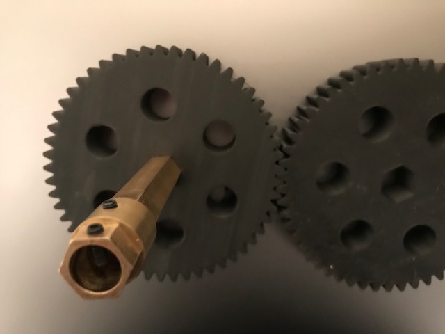
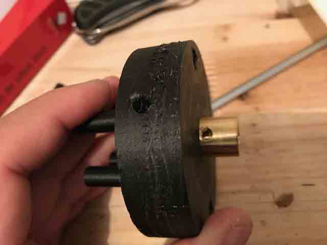
The gear has a shaft to insert an hexagonal axis.
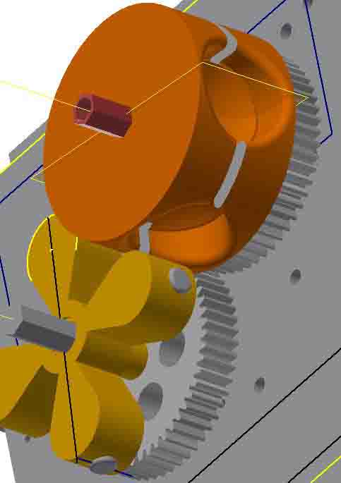
Two gear working together, the drum rotates left hand (orange ) and the squeezer rotates right hand (yellow).
Simulation squeezer and drum.
This simulation is very important because it shows the squeezer and drum working together and calculates the correct dimensions and the correct positions of the pieces.
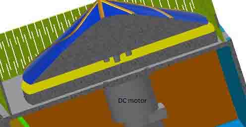
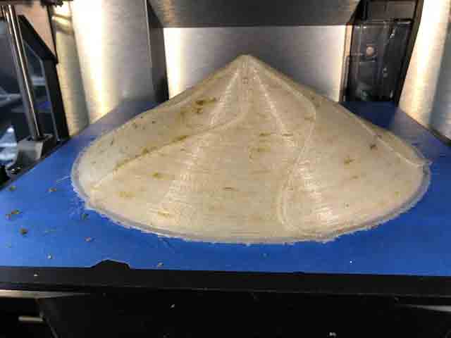
On the top of the machine.
On the top of machine we have other dc motor to rotate a cone to move the lemo. This will supply the machine with the stock. This second motor dc runs at 24 V.
The cone on the top, to throw the lemon to the feeder (blue and gold).
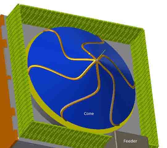
The feeder supplies with only one lemon to the drum.
This picture shows the fully assembled lemon squeezer machine.
This video show the simulation of all parts of the machine working together..
Video.
Simulation Lemon squeezer machine.
Right mouse button to play video
Week_20
This is the last week. During this time I described the project development made on the lemon squezeer machine. I made the body with plywood, the main parts, like the squeezer, drum, feeder and containers were made on ABS. The top of the machine was made on PLA using a 3D printer. The two main gear were made out of carbon fiber. The two main shafts were fabricated with a lathe and a milling machine, on bronze. The shaft on the squeezer has two ballbearings, because it needs to support the force exherted by the motor. In my case, I made some parts during weeks of the academy.
Desciption of the machine.
This squeezer machine has a spinner on top which is connetced to a DC motor. This part rotates for the lemon to go out to the feeder. This part has an infrared sensor and two solenoids which work together in feeding the lemons one by one. This way, the lemon goes to the drum and the knife cuts the fruit in half. On half stays within the drum, and the other half rotates until it falls into the drum again. The squeezer presses the lemon with the drum and the juice falls into the container. This container has a grid or sieve to prevent the lemon seeds from falling. The squeezed lemon is then punched outside of the drum.
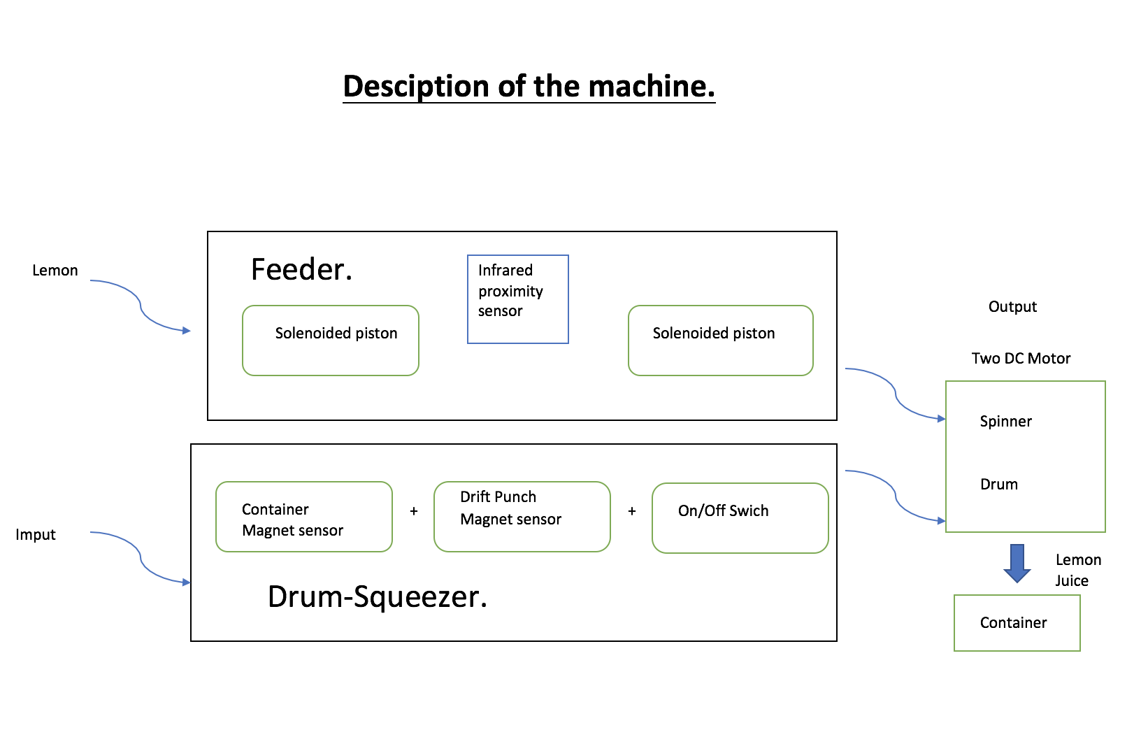
Input:
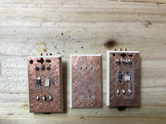
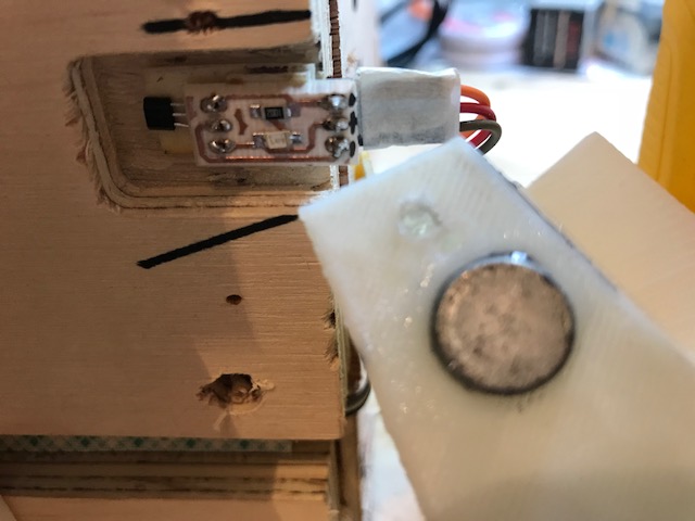
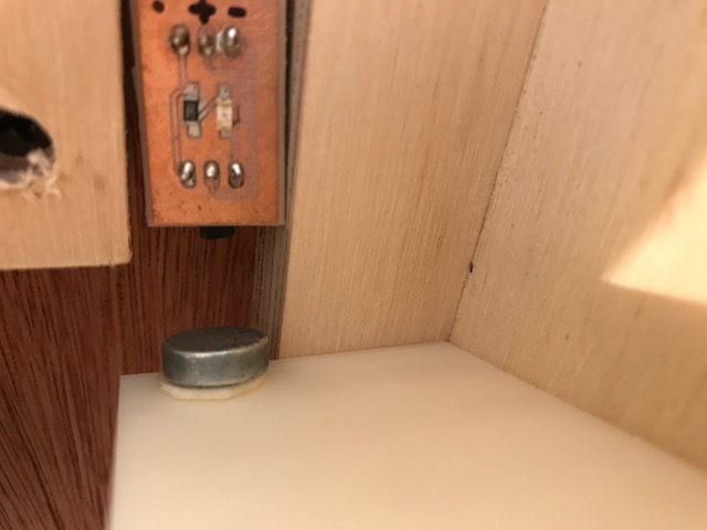
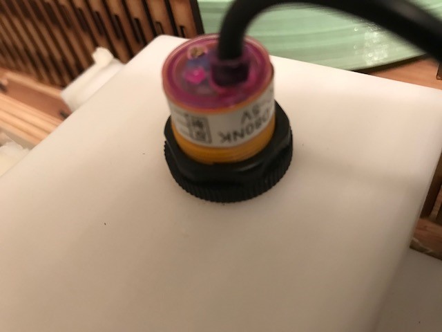
• Infrared proximity sensor.
• Two Allegro MicroSystem Hall Efect sensors.
• On-off switch.
Output:
• One DC motor at 24 V, 7 amperes.
• One DC motor at 24 V, 2 amperes.
• Two solenoids pistons.
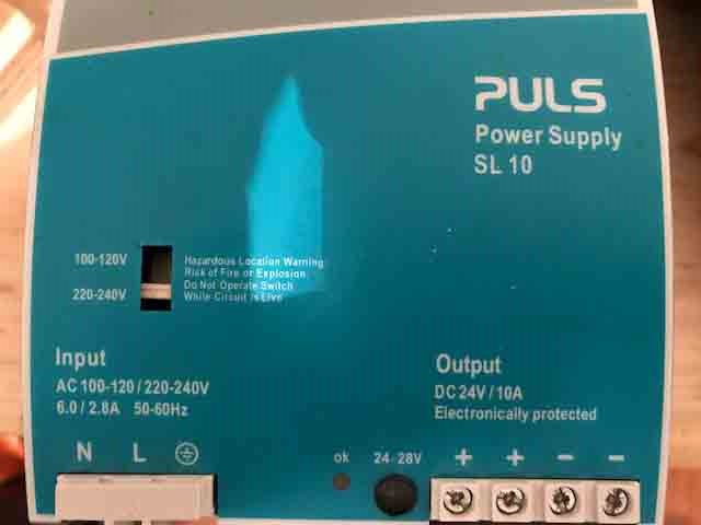
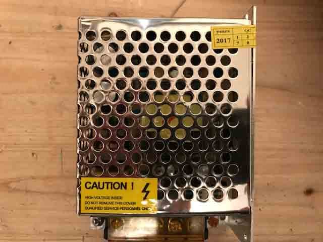
The power.
• One DC power supplier at 24 V, 10 Amperes.
• One DC power at 5 V and 5 Amperes.
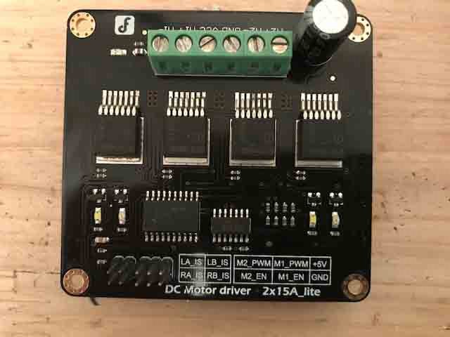
Integracion
This machine has an ATmega328p microprocessor, within a modified satsha kit which controls 3 input devices and 4 output devicers for the operation of the machine. It uses one motor driver at 24 V , 15 amperes for the DC motor and one relay controller for both the solenoid pistons. The software was written in the arduino IDE.
Machines used for the final project.
Pieces:
• 5 pieces made on ABS.
• 3 pieces made on PLA.
• 3 pieces made on cabon fiber and kevlar.
• 2 axes made with brass and one for the collar to secure the squeezer axis.
• 13 pieces on plywood
• 5 pieces on MDF.
In this project there are:
• Body made with plywood cut in the Shop boot.
• 3D printer on PLA, ABS, carbon fiber with kevlar.
• Lathe made two axes and a collar.
• Milling machine made hexagon axis.
• The guard was made on MDF with laser machine.
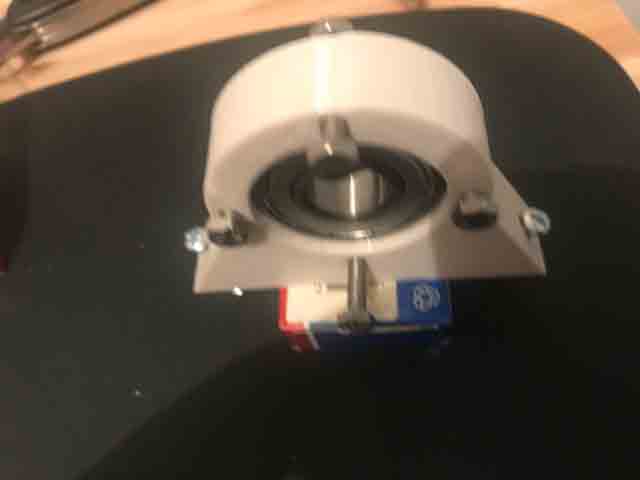
• Two ballbearings for squeeze axis.
• Inventor as the CAD software.
Materials for this proyect.
• Plywood for the body.
• ABS for the feeder, drum, squeezer, container, grid.
• PLA for th spinner.
• Carbon fiber with kevlar for the gear.
• Brass for the axes.
Conclution
This machine works fine currently, but this model is only a prototype. The lemon is ripped apart by the knife. I will work on improving that part in the future.
Description: Diferent part.
The body.
The body was made on 3 mm thick plywood. The width is 30cm for all 6 sides. This makes the body a cube.
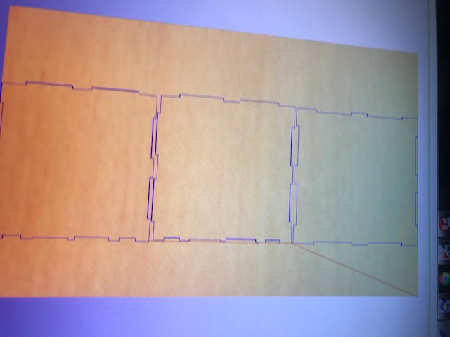
The Guard.
The guard was made on a Laser cutter. I cut the four parts for the top of the machine. The guard is flexible. The material is 3 mm thick MDF.
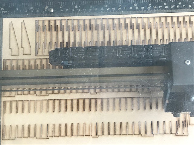
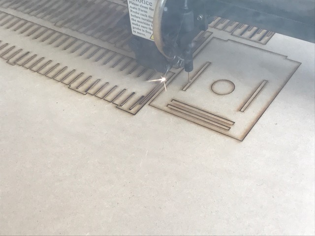
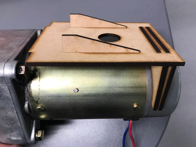

Fig 7. Flexible Guard
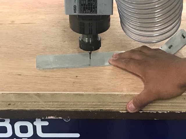
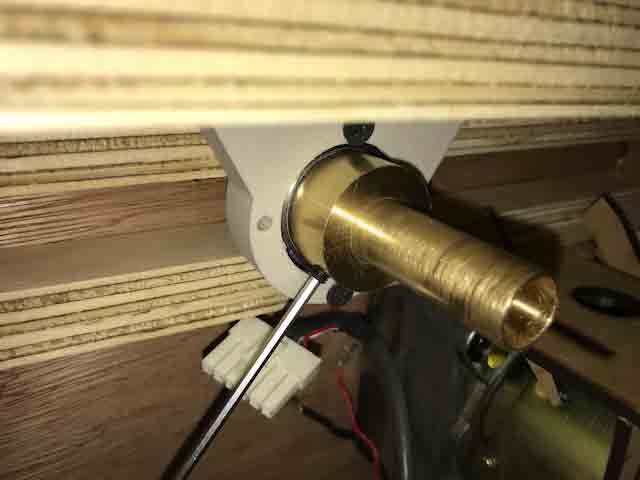
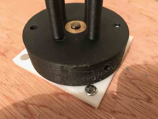
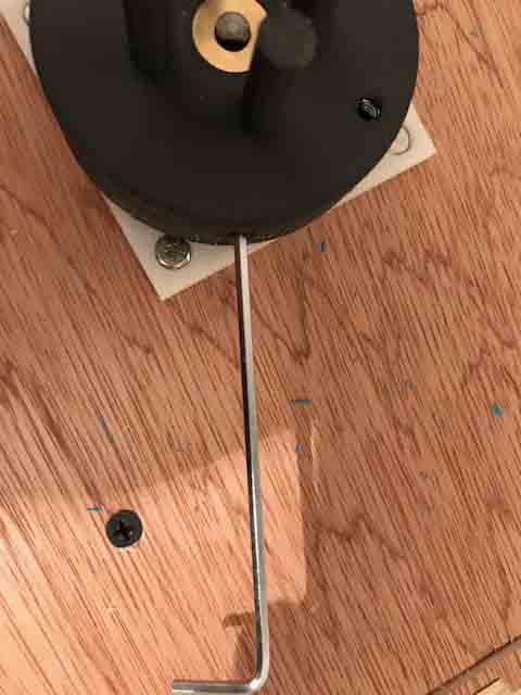
The shaft.
I made both axes on bronze. For this purpose, I used a lathe and a milling machine. The firt step is lathing the material to a diameter of 17mm. The next step is using the milling machine with a divider head for making an hexagonal shaft.
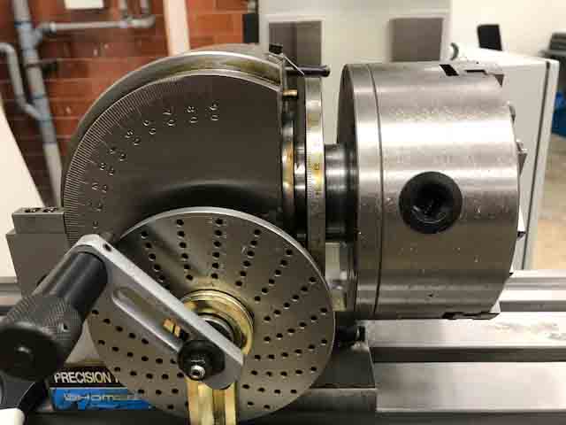
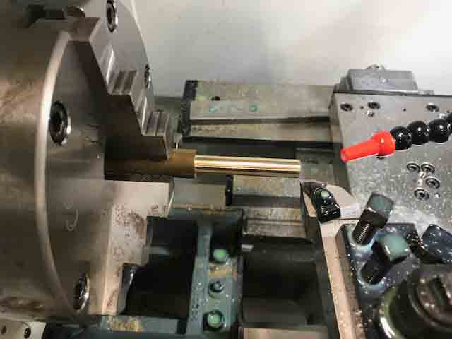

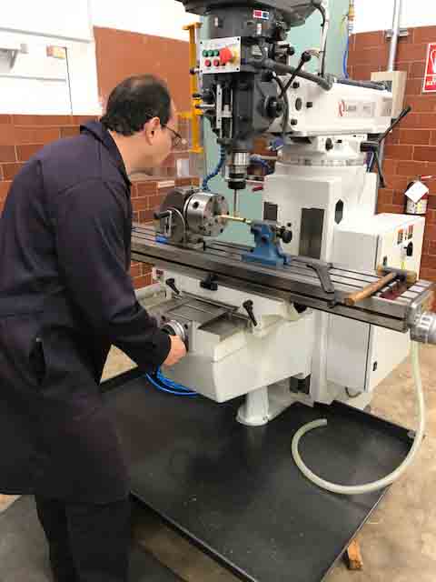
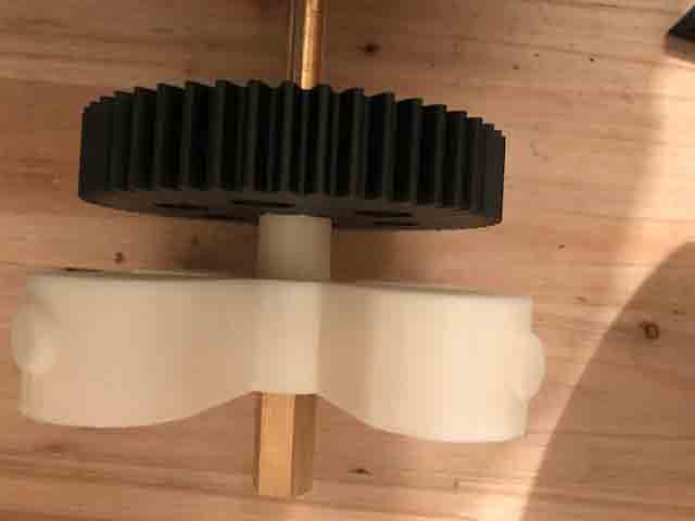

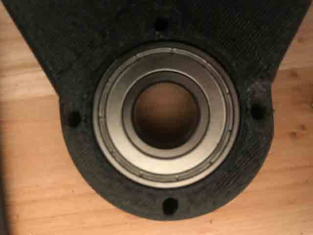
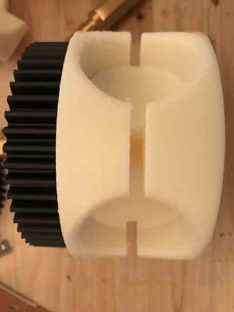
Fig 15. Axis, drum and gear.
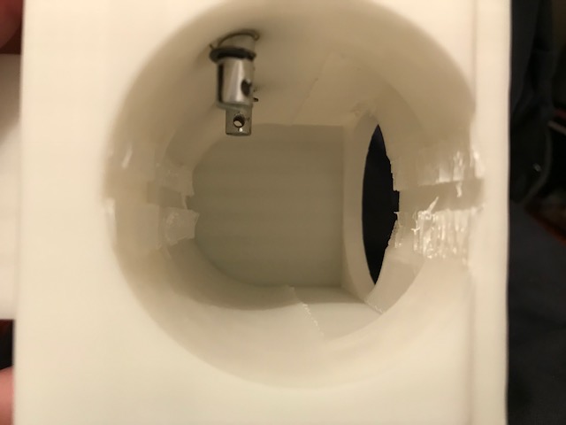
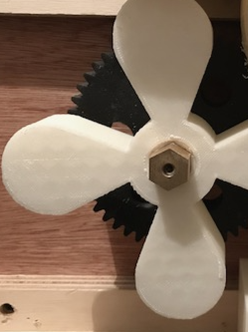
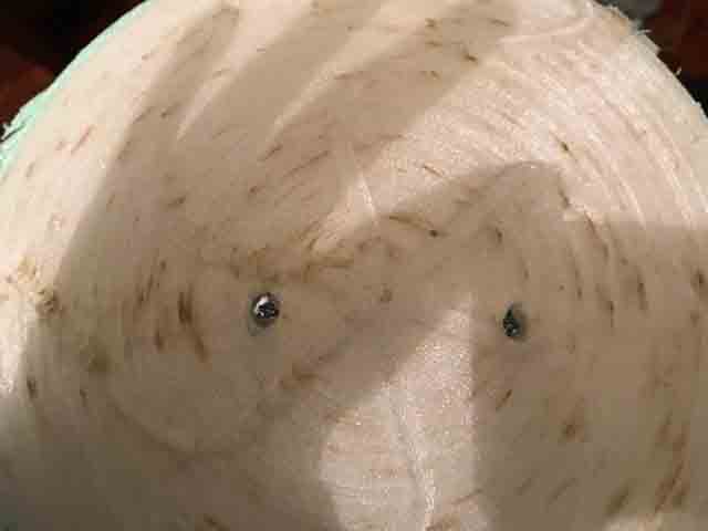
The Drum.
This part holds the lemon for cutting it in half. I had to trim the interior psrt of the drum, so that the feeder can throw the lemon outside.

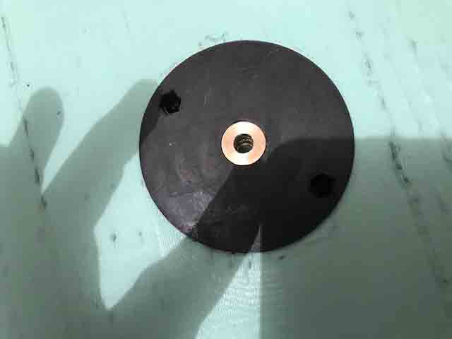
The Gear.
This gear was made with carbon fiber in a Markforge 3D printer. This gear has 53 teeth. This material is very hard, and that hardness is necessary for the tramsmition part.
DC Motor.
The DC Motor works with 24 Volts and 7 Amperes. When it’s powered, the DC motor uses about 10 Amperes.
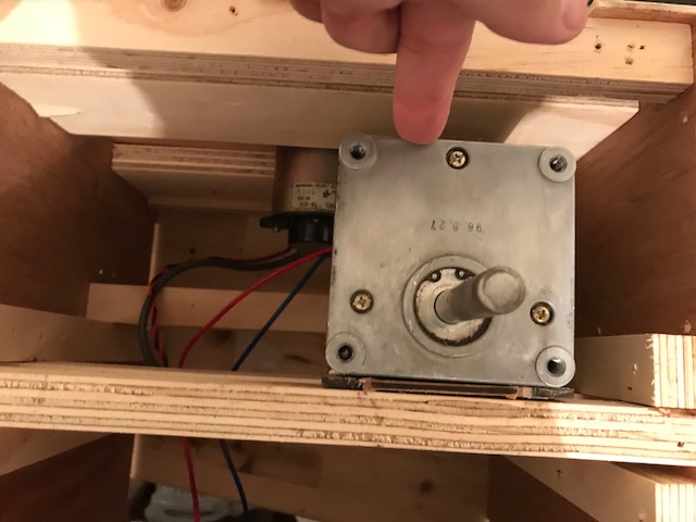
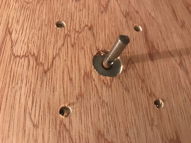
Fig 23 The DC motor assembled on the frontal part of the machine.
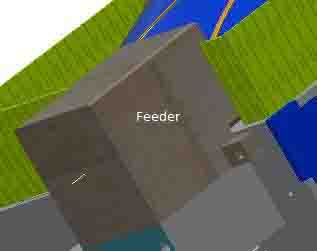
The Feeder.
The feeder has two solenoids, which feed the lemons one at a time. It also has an ultrasonic sensor to detect whether or not the lemon is inside of the machine.
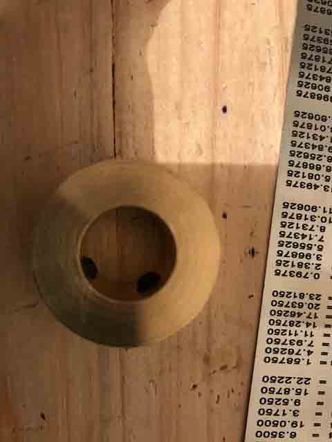
The squeezer.
This piece was made with PLA. It is not so strong, this is the main problem with the machine because it can be easily broken.
The top on the machine.
This part distributes the lemon to the feeder.
The Electronic and power.
The board I used the miny satscha kit whit extra pin for positive and negative and led aditional for the power and extra led on dgital pin 13, the resistor for the led 1k ohm.
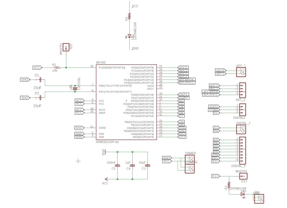
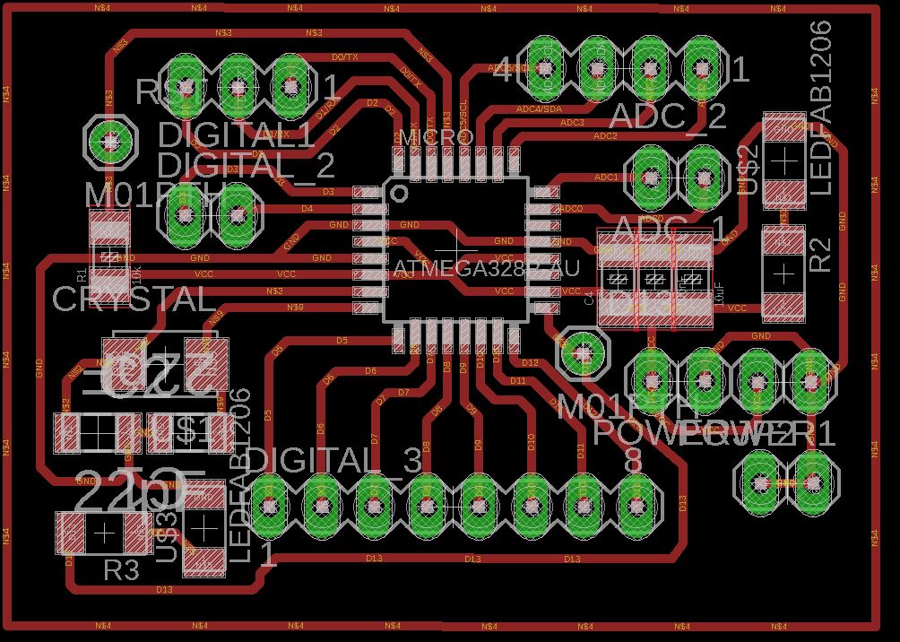
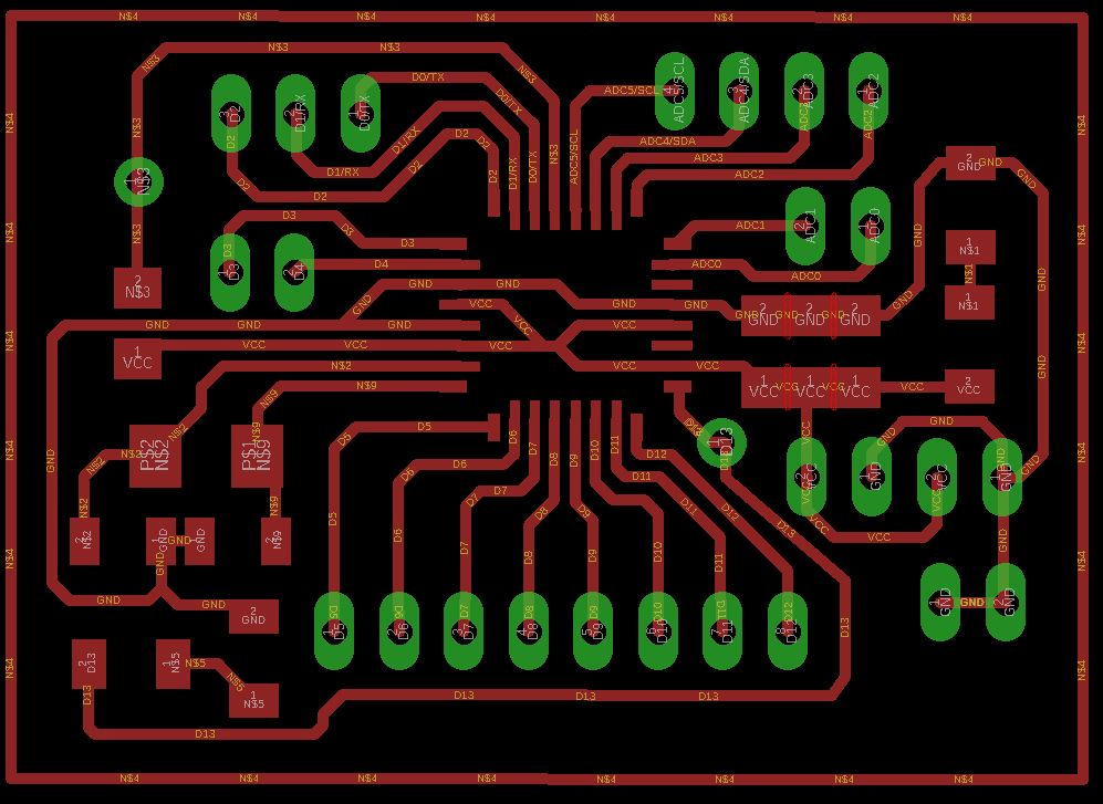
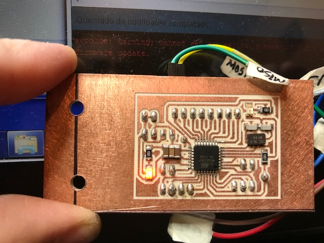
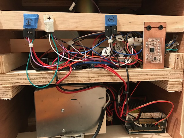
Mini Satscha board.
Mini Satscha Shematic.
Firware for the Lemon Squeeze Machine.
Final Video
Video: Lemon Squeezer Mahine
Right mouse button to play video
Return: Final Proyect
Read MoreFiles on Inventor 2017
Ribs
Safe guard.
Plate
Support part.
Gear.
Rowlock
Drum
Click on
Filter
Dish
Knife
Receive
squeezer
Hoperr
Spinner
Container