This week's assignmet was to make and program a FabISP, using one of the available designs. At first, I decided to make the classic FabISP. This is Neil's original version of the ISP board. The problem was, I could not find a ".brd" file of the design, so I had to download the ".png".
I use Flatcam as a CAM tool when generating the G-code for my milling machine. Unfortunately, FlatCAM cannot use .png files, so I had to convert the file to an .svg. I did this using FabModules.
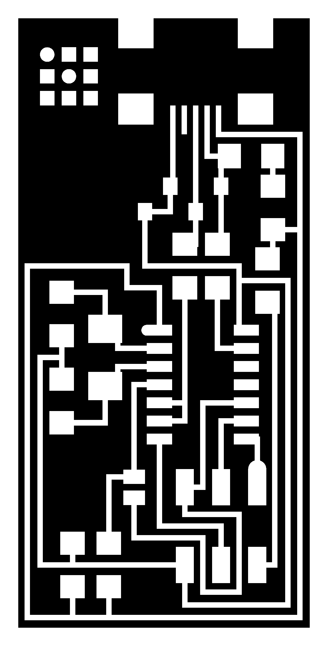
I downloaded to .svg output file and imported it into FlatCAM. However, when I was about generate then code, I realized that for some reason, the width of the board was set to 30v 000 milimeters, I was going to cut a 30 m wide PCB. I couldn't just scale it, mostly because I needed to be sure of the components' dimension, and I had no idea what they were. Thus, I decided to change to a different design. I settled for the Ali. I downloaded the ".brd" file, and opened it in Eagle.
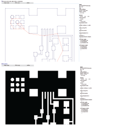
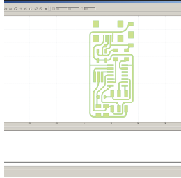
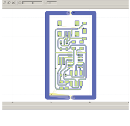
I then exported it as a Gerber file, and loaded it into FlatCAM. To open it, click on "File" then "Open Gerber", and select your file. Once you do that, this is what you get:
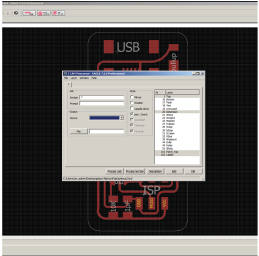
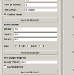
Next, I edited the plottong parameters, and generated the cutting geometry. These are the parameters:
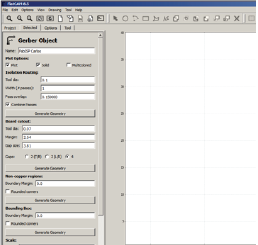
Once the geometry had been generated, I edited the cutting parameters, These mainly include the z-axis parameters:
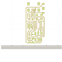
I now have a G-code, which I can send into my milling machine. But first, I have to generate a second g-cout for the board cutout. The steps are similar, but the parameters change a little bit.
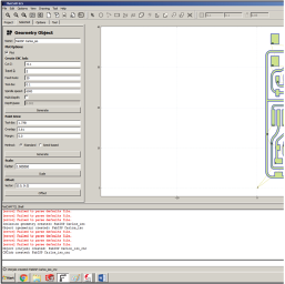
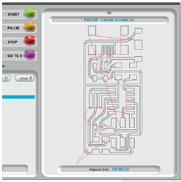
This process generates a geometry, and finally a G-Code which is sent to the milling machine. We use a Wegstr cnc machine which comes with its own software.
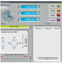
I positioned the board and the tool using the arrow keys, and set a "zero-point". Afterwards, I loaded the G-code and started milling.
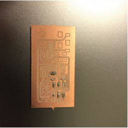
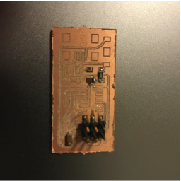
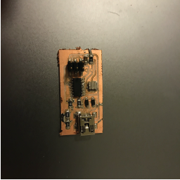
The next step was soldering the board. I started with the traditional method. Using a soldering iron and lead.
I however, am not very good at soldering, and ended up screwing up 2 PCB's.
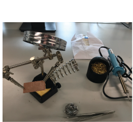
Finally, I used a different method. I used flux and a heating gun in order to solder everything to the PCB. This was my new soldering station:
In the end, i managed to have a complete board, though I'm not sure if they work yet, i'll have to wait and program them
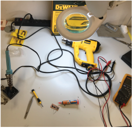
Finally, it was time to program the board. I followed the instructions available in this page. Because I'm a mac user, I had to download X-code in order to program the board, Fortunately, I already had it, so I only needed to use the terminal to acces and modify the firmware.
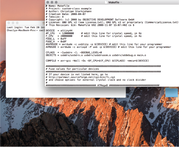
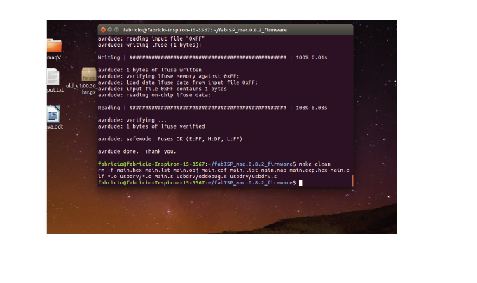
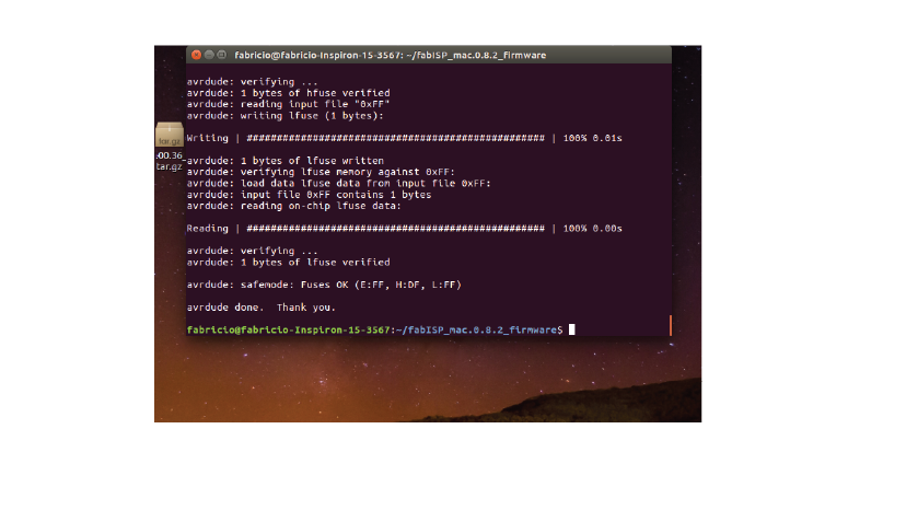
After modifying the firmware though, I tried programming the board with the command line in Mac, and it didn't work. I had followed the tutorial and had all of the necessary drivers, so I did not understand. Fabricio told me to try his computer and my FabISP worked! Here are the commands I used.

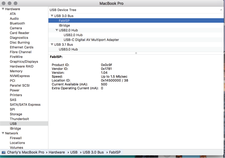
After programming, I desoldered the 0 ohm resistor and reconnected the FabISP to my computer. I checked within the system information to make sure that the computer recognized the device: