
Just as with the input devices, I wanted to use this assignment to move forward with my final project, so I decided to make a dedicated board in order to control both a stepper motor and a servomotor. Each of these motors will serve a purpose in the FAB-Brewer. The stepper will be the main actuator within the peristaltic pump, while the servo will work as part of a self-made electro-valve. Now, because I was going to travel outside of the country during this week, I had to start earlier with the assignment, and I began making my board before Neil's lecture. This meant that I missed some important key points.
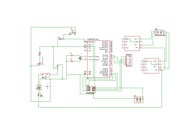
While I was checking the available examples, I wondered why these boards did not use the FTDI pins. I started checking other people's reppositories and found no answer whatsoever. So when I designed my board, I designed it with the FTDI pins. However, I did not consider the following. First, most output devices need currents and voltages higher than those a computer can provide, meaning that an external power source is necessary. Second, other than transfering data through the serial port, I really haven't used the FTDI pins for anything else. Given that I did not need to monitor the data, and that I could program the board through the AVR-ISP pins, I really did not need serial communication, so the FTDI pins are innecesary. In the end however, using them proved really useful when routing in Eagle. Anyway, just as with my potentiometer, I had to check how the H-bridge worked, and select a specific microcontroller. I settled for the ATtiny 44, becasue I needed the extra pins. Initially, I used the ATmega 328, biut I had to change microcontrollers. I don't particularly like the Atmega 328, because it's rather hard to solder. Here's my original schematic:
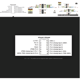
I also checked the Attiny Pinout, to make sure I was connecting my H-bridges properly. They only need digital inputs, so most pins are ok. The servo needs to be connected to a PWM pin, so it's important to double check the connections.
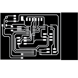
Once I changed microcontrollers and reviewed the pinout, I redid the routing. I had to use a 0 ohms resistor, because I had problems finding some paths. Here's what my board looked like.
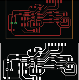
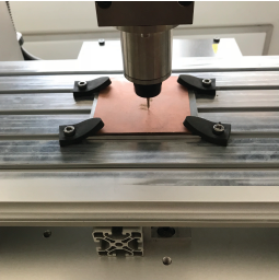
I used the monochrome image to get the G-code using fab-modules. I milled it and obtained my first board.
I was advised, however, to change my board, because some of my paths had diameters of 0.2 milimeter, and they would not be able to stand the current which would flow through them. I had no clue as to how to route my board, so I checked the repositories of previous students. One of my friends from Fabricademy, Luis Dulanto, had taken the FabAcademy on 2017, and he made a similar board, so I based my routing on what he had done.
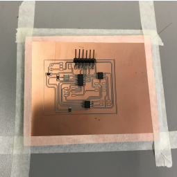
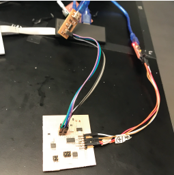
After milling, I soldered my components:
I wanted to program my board using the AVR-ISP mkII, but it wouldn't work, even when the device communicated with my board. I know there was communication, because a green light indicates that the programmer recognizes the presence of a microcontroller.
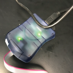
In the end, I had to do it with my FAB-ISP.
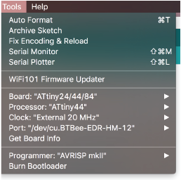
Once again, I had to change the settings with which to program the board.
And.... the bootloader burnt properly.
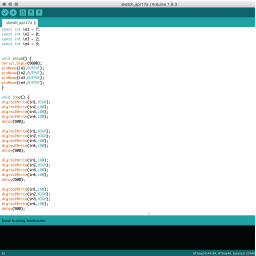
I then programmed the stepper motor. I used a bipolar stepper motor, with 8 internal steps. This is the program I created:
After compiling and uploading....
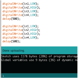
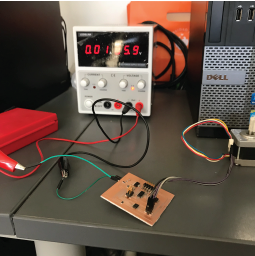
It worked! I connected it to the external power source and checked to see whether or not the code run properly. The video below, is separated in 3 parts:
You can download my code from here and my schematic and board from here and here.