Machine Design
Week 15 & 16
ASSIGNEMENT
- design a machine that includes mechanism+actuation+automation
- build the mechanical parts and operate it manually
- document the group project and your individual contribution
- actuate and automate your machine
- document the group project and your individual contribution
SOFTWARE USED
- Fusion 360
- UP
- Cura
HARDWARE USED
- UP 3d printer
- Ultimaker 2 plus
- Dremel
FILES
Files of the parts we added or changed from the axidraw machine on thingiverse.
Brush holder F3D
Brush holder STL
Inkwell F3D
Inkwell STL
DrawingMachine_base_modified F3D
DrawingMachine_base_modified STL
GROUP ASSIGNEMENT
Machine design group page
This page shows the group work and the machine made.
In the group, my involvement was to make the machine,
check its operation manually and work with Nicolas on the end effector.
LEARNING EXPERIENCE
For this week's assignment, we decided with the team to make a drawing machine.
More particularly, a calligraphy machine.
We looked , Nicolas, Axel, Denis and I at different drawing machines and decided to work with an
axisdraw base.
An is downloadable on thingiverse(see link above).
We started from there
There are two ways to build it:
3 d printing or from laser cut panels.
We shared the tasks among us:
Axel, Denis's assistant took care of the supplies and was there in support
Nicolas was in charge of the analysis of the machine, the electronic and the code.
I took care of the mechanical part, printing and construction.
During this first week I worked mostly alone on the 3D printing parts and assembling them .
I received from Nicolas a summary of the way the machine worked with the 6 pieces to print.
I did also some research and saw some videos on it.
We had at our disposal two 3D printers: the UP from TrioSlab and the Ultimaker 2+ from the Fablab ULB.
Time was running out and I had to finish the mechanical part of the machine for the Tuesday of the first week.
The plastic prints are on these two machines very slow.
So I opted for security by launching the most complicated parts (central) on both printers.
My preference was for the UP also because it was easier to work with Axel next to us.
Printing the small parts was not a problem.
The central parts have been the subject of several tests and settings of the printer.
I used ABS and for the first impressions, the parts did not print well.
They bent and peeled off the hot plate.
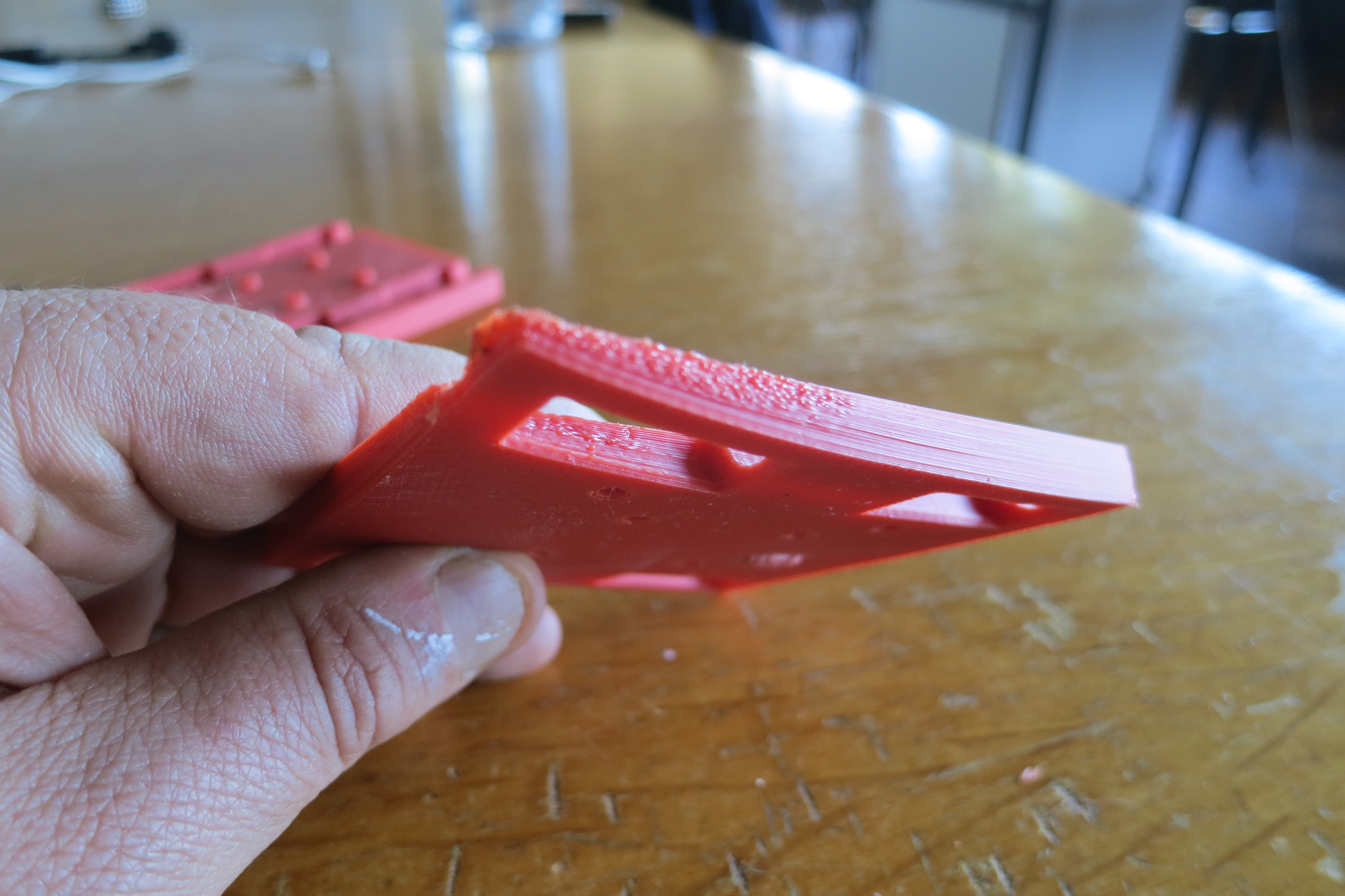
I changed the settings of 100 pc of filling to 75 pc.
The idea was to spread the effort in the structure of the material, which worked.
All the parts produced with this setting were perfect.
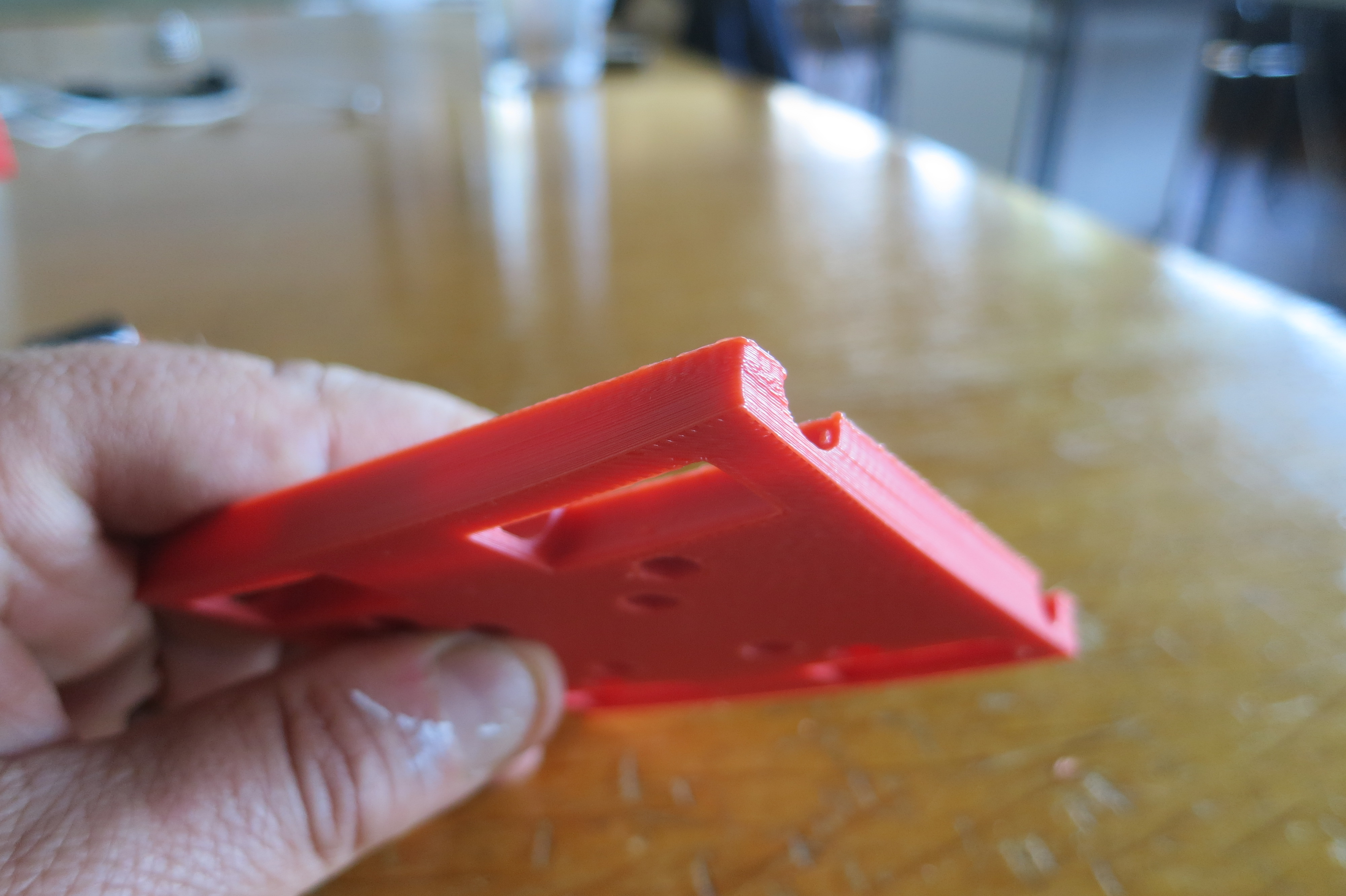
I also set a program setting that keeps the warming board running for 15 minutes after printing.
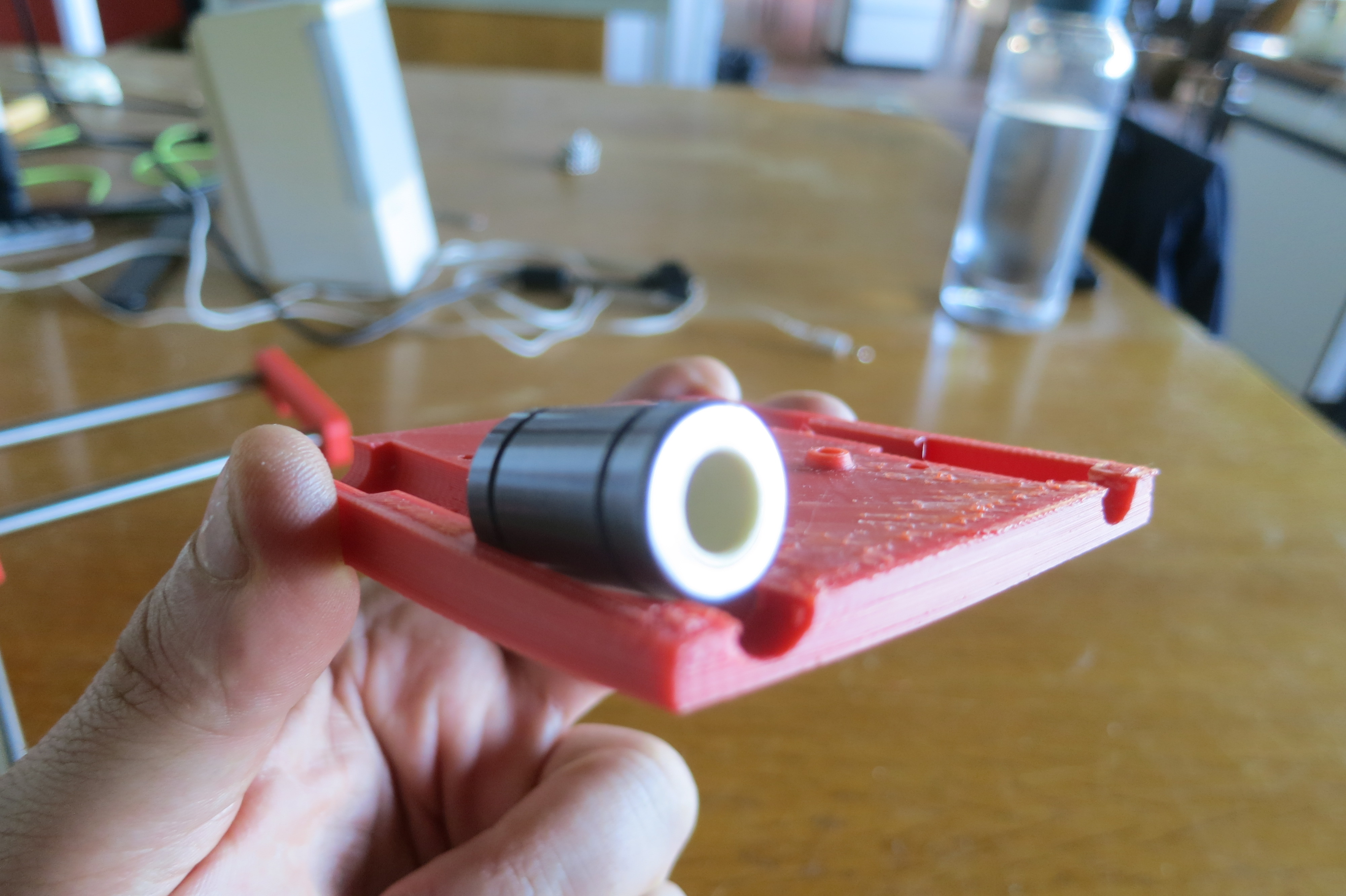
We also had a problem with the size of the bearings that slide on the rectified pins.
The dimensions of the pieces received did not correspond to the order.
I had to modify the central parts on Fusion 360.
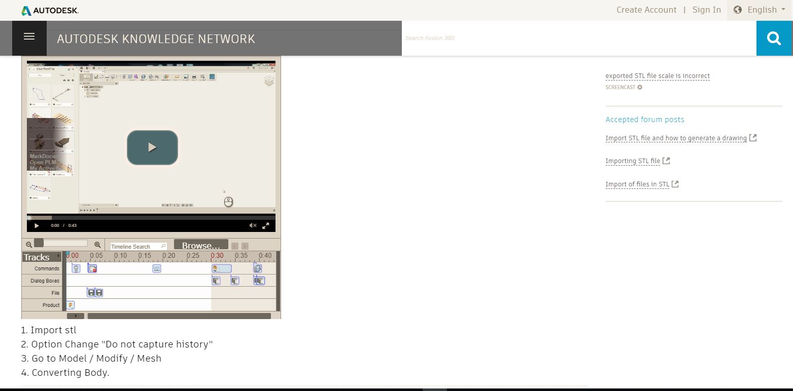
MODIFY THE STL
To do this we must go through a procedure a little complex and unnatural in four steps .
It is documented on the Autodesk website with a fairly clear video tutorial.
I added 1 mm to the hole to fit the bearings dimensions
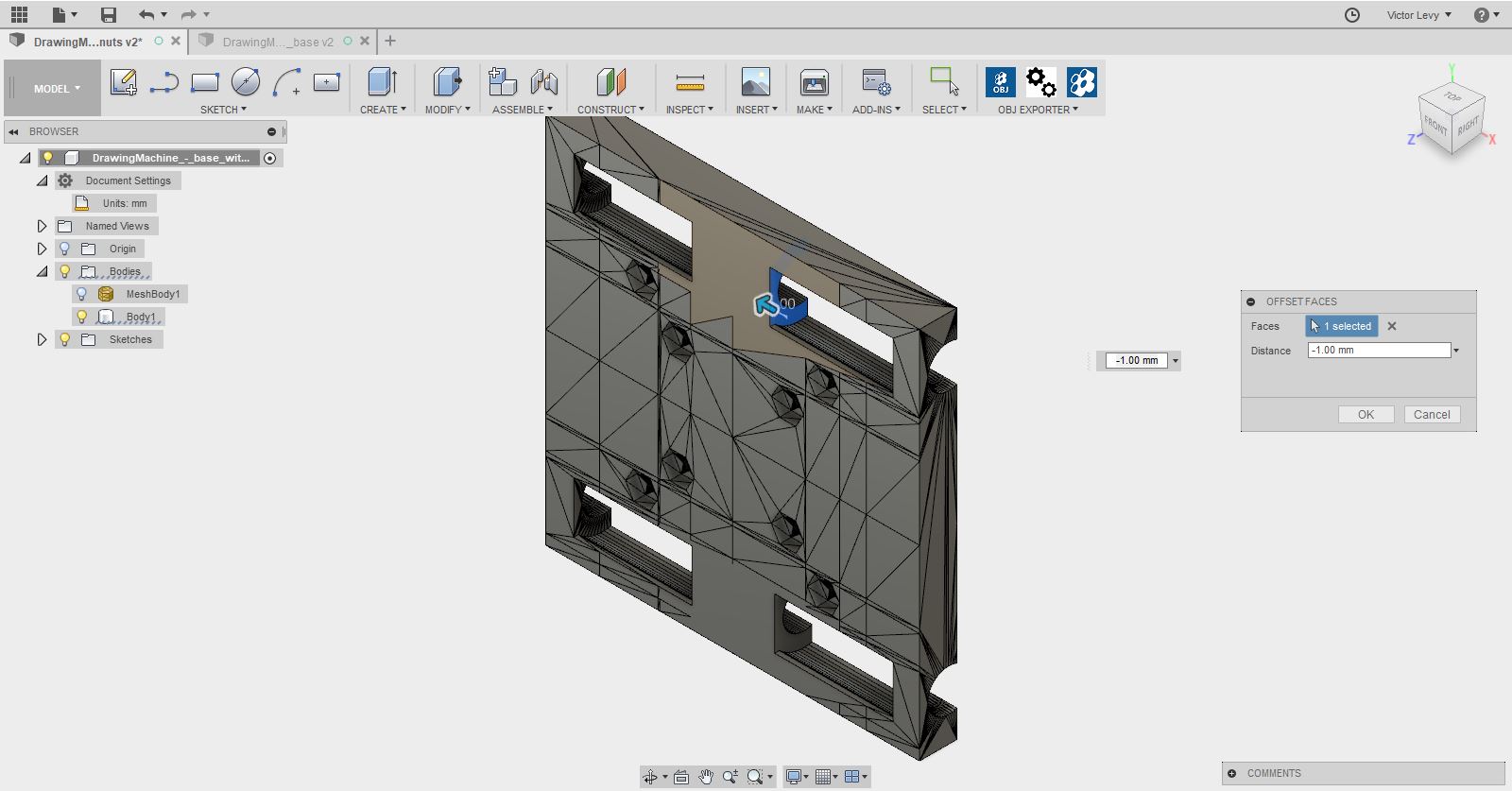
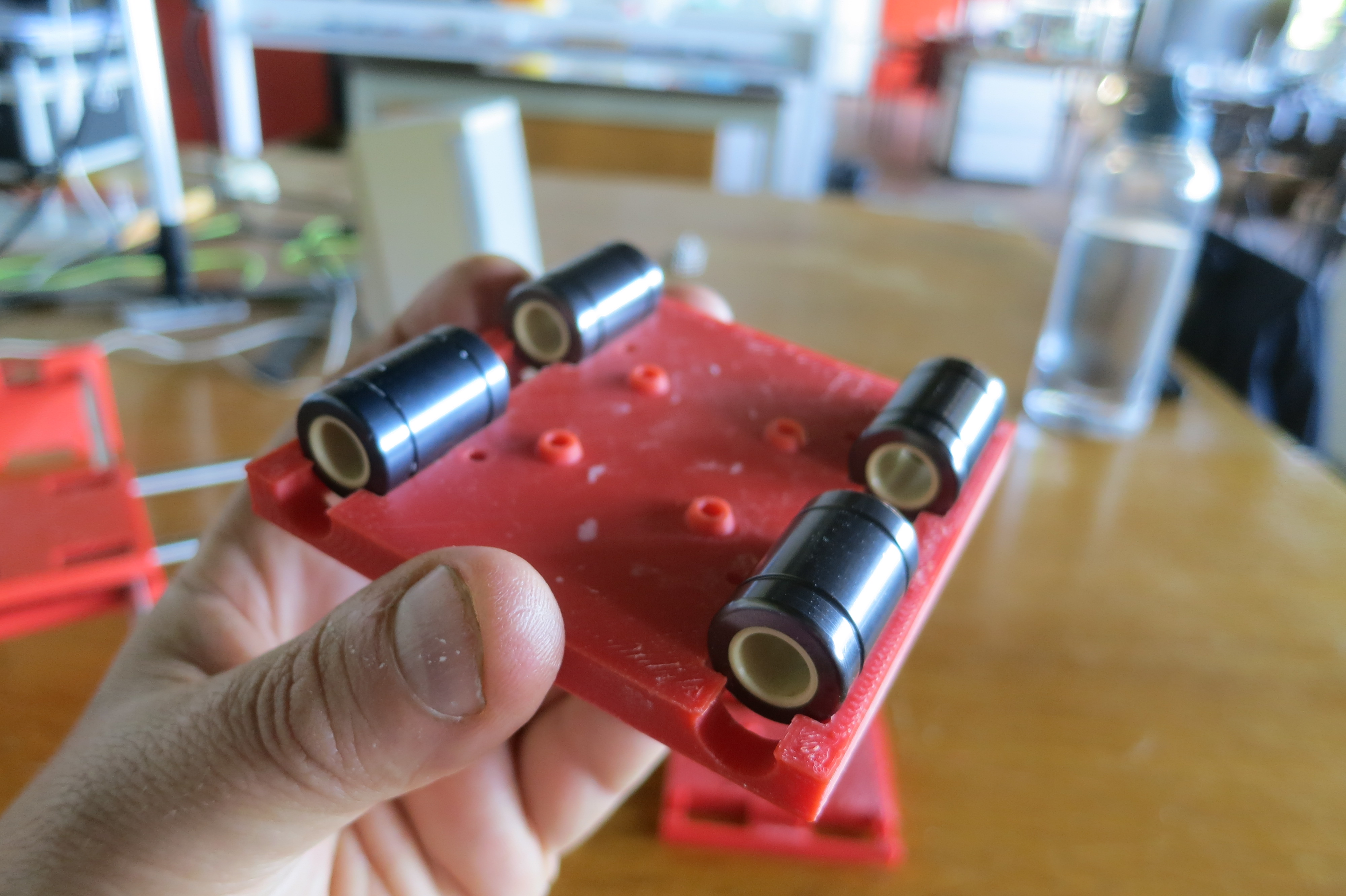
unfortunately I did not pay attention to the diameter that was also wrong.
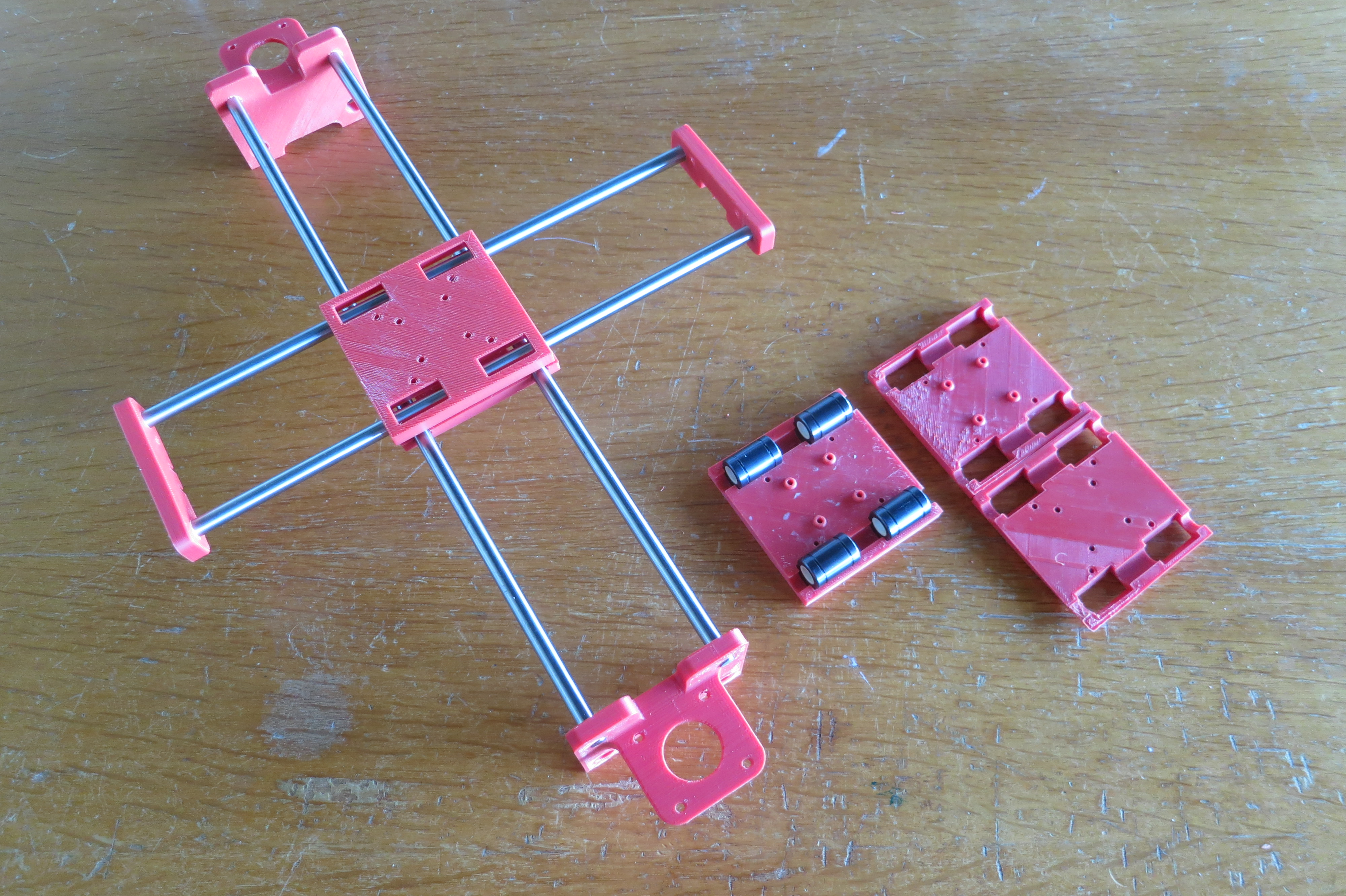
The two cylinders do not fit completely in the two central parts,
I had to add nuts to mount the four ball bearings that serve as a reference to the belt.
The placement of the belt was not simple ...
It had to be passed through the center in the right direction.
HOME