Computer Controlled machining
Week 8
ASSIGNEMENT- Make something big (on a CNC machine)
- Rhinocéros
- Fusion 360
- WinPC-NC
FILES
Julien's chair original Fusion 360
Julien's original dxf
Julien's chair modified Fusion 360
Julien's chair modified dxf
GROUP ASSIGNMENT
CNC group assignment
LEARNING EXPERIENCE
This week I decided to concentrate on the tool to learn.
I decided to use JULIEN's upcycling Chair wich was developed in my design course.
I am proud of him, he is running a very succesful digital workshop in london: L'établi London.
The idea was to recuperate chairs that break in our university.
I love this project and tried to see if I can make it and maybe improved it.
The files we have in the Lab are incomplete, so it was perfect for this exercise.
I have to reverse the way it was build and redesign the file.
I was interested to use Rhinoceros and Fusion 360 to see the difference and the exchange of files between the 2 software.
I worked with my colleague David and exchanged on different workflow.
I did the drawing on Rhino and prepared the cam file on Fusion 360.
I also discovered that Rhino is very much intuitive for me.
Also,I changed the way to document the assignment.
I first started to screenshot and then illustrate with a description of the screenshot.
Before, I was doing that differently: I wrote what I did/learned/experiment/failed using several screenshot and went back on the steps that I couldn't describe.
Much better way to do the path of learning and adding the things that you would have skipped.
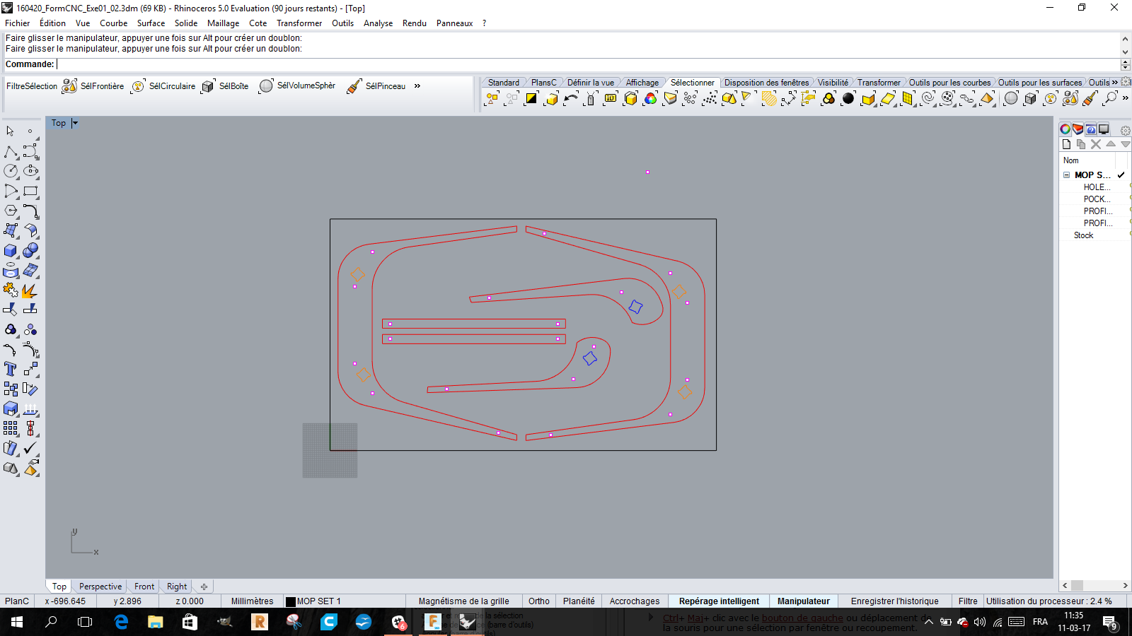
The files were done on Rhino. I never used this software before.
No tutorials, just observation of the structure of the software and trial and error
David helped me on understanding the commands on the top of the screen that allows you to do what you want to do(move,group,rotate,copy,diameter ....)
Interesting way of working, with shortcuts and many options to draw a form.
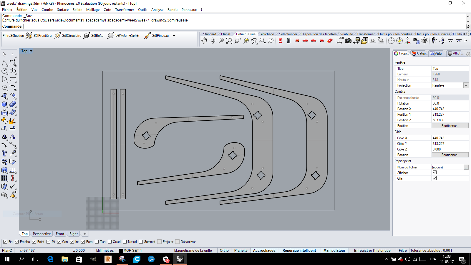
I started from the files we had, 2D dxf files that Julien left us.
I had to place the pieces on the stock 100*60 and place it under the Z axis
Put it on the origin too,move the pieces,copy them...
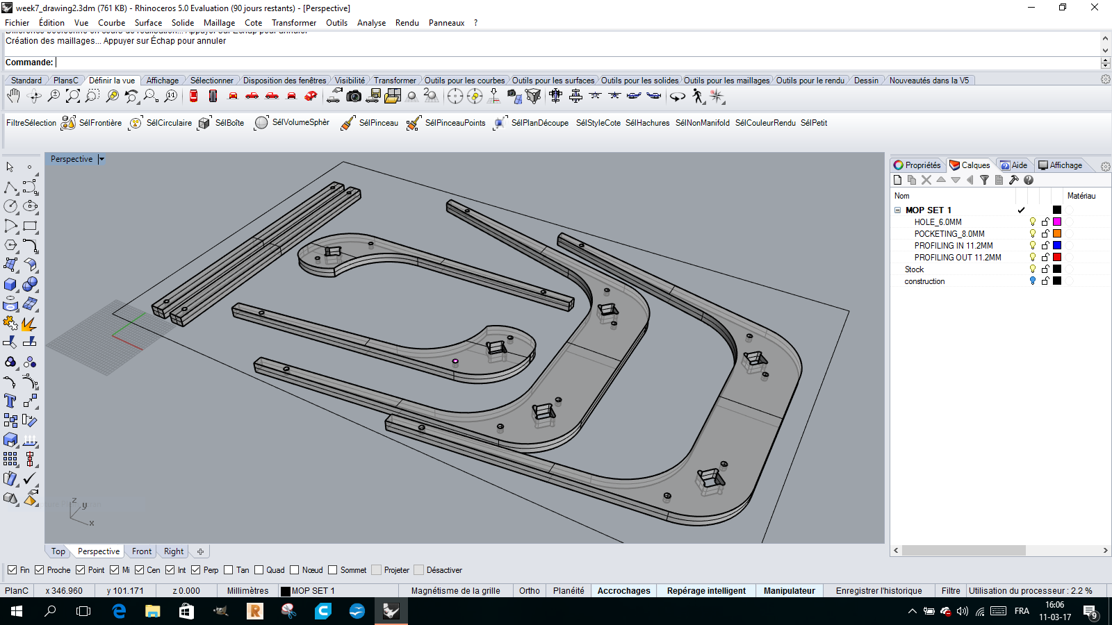
I first extrude the 2D forms in Z axis, 17,5 mm .
As I wanted to add wood cylinders to join the two pieces of plywood,
I used the boolean function to subtract the 9mm cylinders from the plywood parts.
I watched how to import Rhino files to Fusion.
In the tab where the drawing files are, you have to click on the UPLOAD button.
you select your file on the computer and send it to the cloud.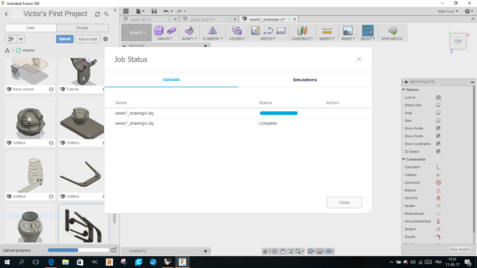
It will be transformed into F3D format and will be displayed in the file window in a new document.
It worked perfectly.
I was a little bit lost with the XYZ,the way it is on my default page on Fusion.
It is not very intuitive, but I will get used to it.
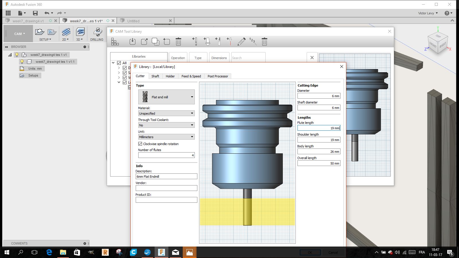
I went on the cam mode in Fusion,used the function 2D contour.
To prepare the Cam file that will generate the Gcode,
the machine must understand in which reference system the drawing is made.
It is in the SETUP function, we will determine :
The location and direction of the axes
The size of the stock of material
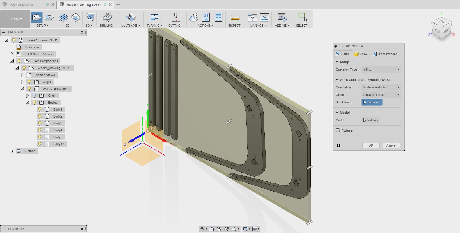
Once done, we will define a tool.
Here we will use a flat end mill of 8 mm.
We will only cut a 2D shape with a constant depth.
This tool will be very good for that.
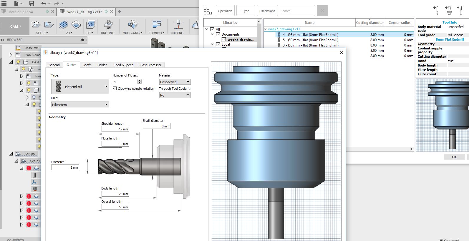
First step is to edit the tool to encode the diameter, the total length of the cutter, the flute.
Then we have to tell the software which path will make the tool, so we have to select a geometry.
In this case it will be the bottom of the piece to cut.
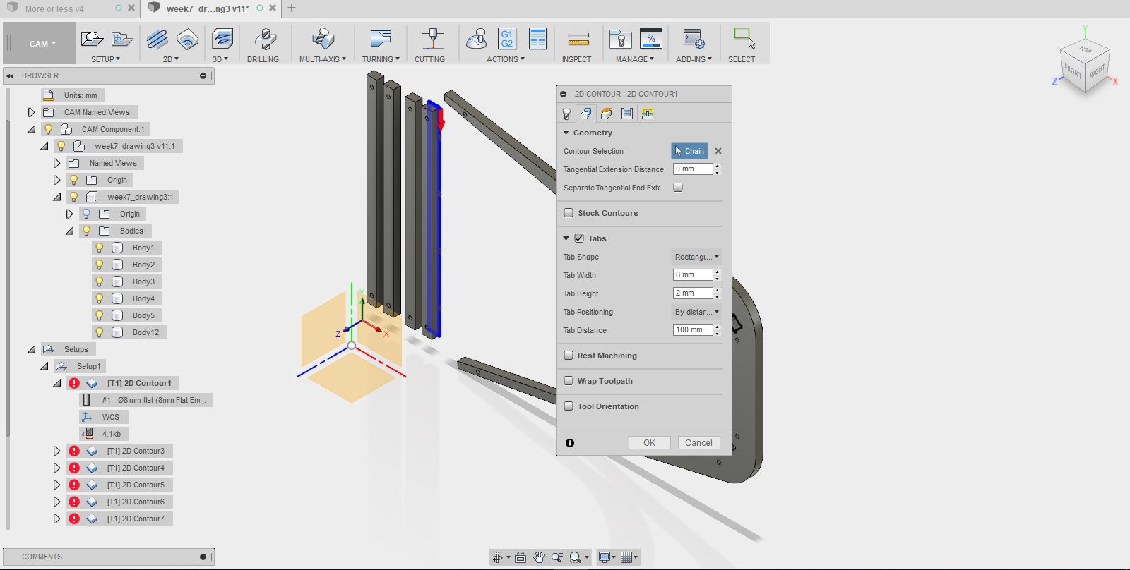
We will also specify if it takes tabs, which will maintain the room during cutting.
It will be necessary to cut the parts after machining.
We will cut the parts over the entire depth of the Plywood.
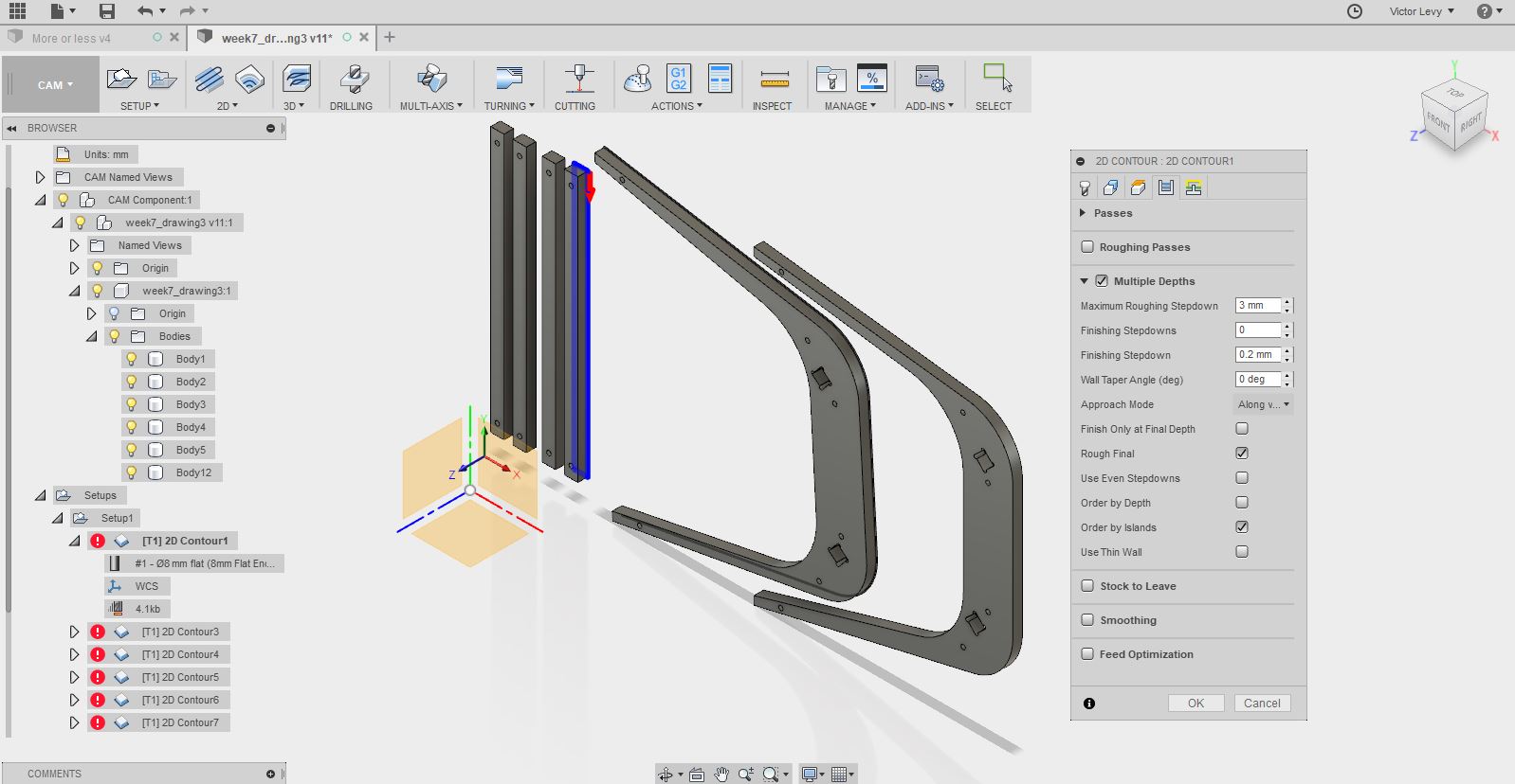
We must give a height of passes, here we will give 3mm, by passage of the tool.
I will do this for each part and will generate the gcode with the postprocess function.
It will take for our machine selection Shopbot iso as output machine.
I went into simulate mode,to be sure everything goes right.
I postprocessed the setup by clicking on it,
Then I had a message of error when generating the final gcode
Then I found the solution by testing each 2D cut and found out that some of them where not correct
I did the gcode another time and tested every 2D cut and also the drilling by generating for each operation a different toolpath
After that operation done,I made the last one with all the toolpath of the different parts of the chair.
Then it was correct.
I opened it on Winpc-nc,placed the forms at the right place for the stock and made the zero point in XYZ and launched the CNC
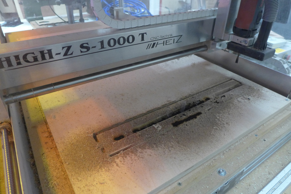
We had a problem of burning wood,at the feed rate of 7,9 and 10 mm/sec
The speed was 20.000 RPM
I stopped the machine and changed the speed rate to 18 mm/sec
Much better result,and no fire anymore
We put back the compressor with air to cool down the drill
It was the best result in terms of cutting
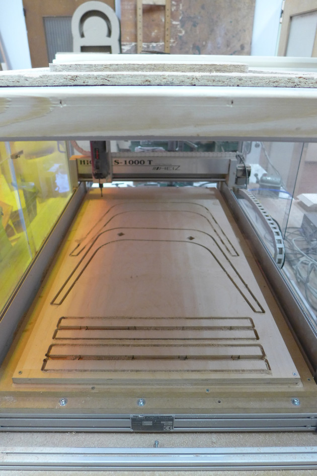
The project was cut but the time to finish was to short
I found out that the square join was wrong,so I had to correct it manualy
By assembling the 2 x 18 mm version of plywood, I found this version too heavy and too massive.
Comparing, we can see that Julien was right and found the right thickness that was the thinnest and most resistant possible.
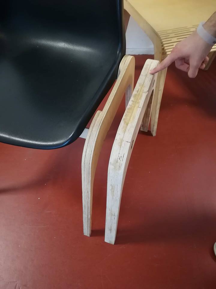
He had received an excellent grade ...
In remaking it, I realize the intelligence of his work.
So I rebuild a version with two thicknesses of 12 mm,
One in meranti plywood and the other in bakelized panel for concrete formwork.
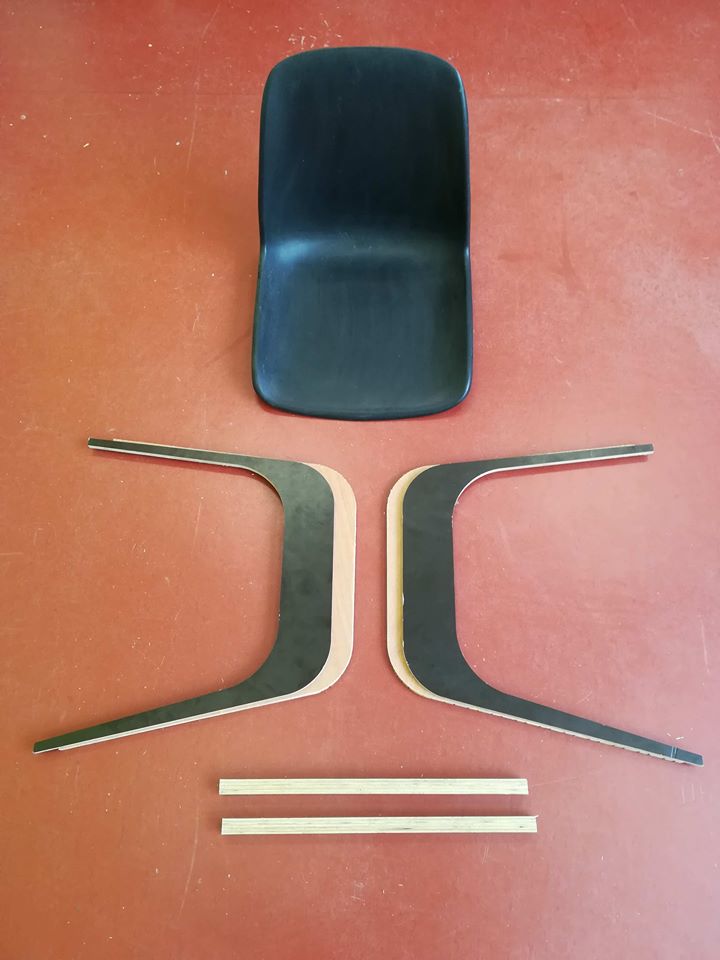
Here is a view of the spare parts.
An image, after assembling in the same street ...
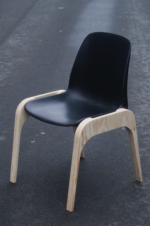
Julien's chair
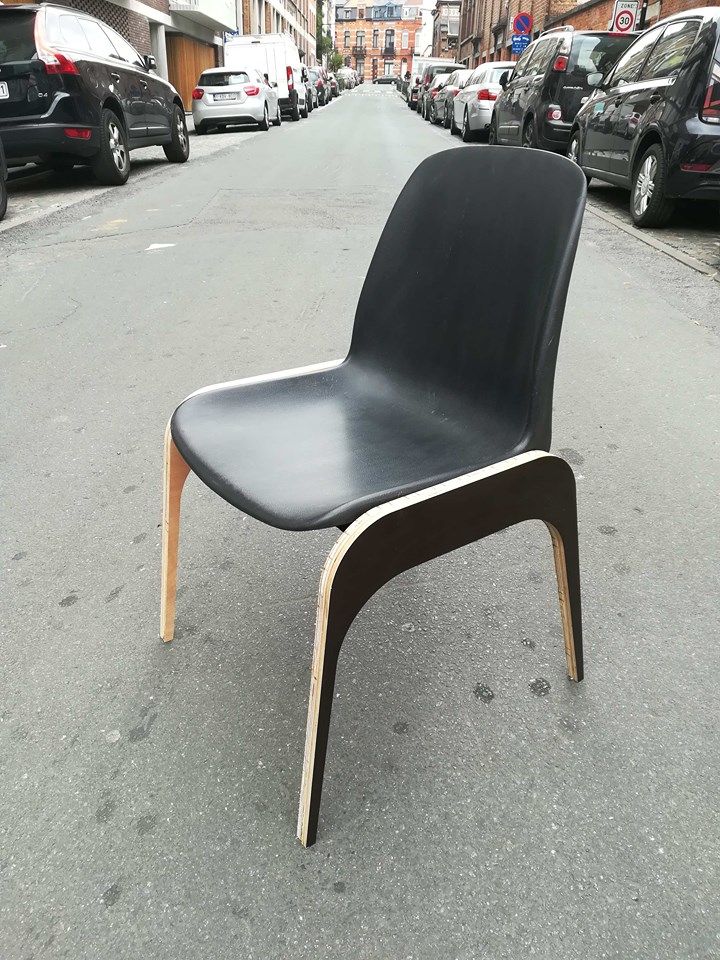
My version of Julien's chair
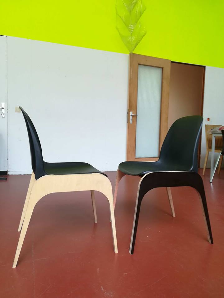
Finally the hero shot: A battle of chairs ...
The files of the 2 versions are above on this page.
HOME