3D scanning and printing
Week 6
ASSIGNMENT
SOFTWARE USED
- 123D
- Remake
- Meshmixer
- Cura
- Scanstudio
- Fusion 360
LEARNING EXPERIENCE
This was quite an interesting week, more close to what I am used to do.
I tried some photogrammetry before, and had a small experience, printing several objects with the 3d printer of the lab.
It was a good thing to start the process again to see what part of the skill is missing.
I learned the basics of photogrammetry.
to use Next Engine scanner of Denis' lab,
to 3D Print with a Graber, a reprap machine and a Ultimaker 2+,
to clean the 3d printing machines.
Origami Remake
3d print coil Fusion 360
3d print coil STL
GROUP ASSIGNEMENT
3d printing group page
3D SCANNING USING PHOTOGRAMETRY
I started this week by scanner using photogrammetry.
I decided to test this technique, because it could alo be interressing for my students.
They all have a smartphone and a good quality camera.
This technique makes it possible to scan by adding software after taking a series of images turning around an object.
Autodesk has developed a series of tools that allow to generate a 3D model that can then be used on 3D drawing software.
They started with a smartphone application 123 make, then a sofware: Remake and now another one : Recap and Recap pro.
I still had a version of Remake before Autodesk removed it and replaced it with the paid version.
So this tool allowed me to model the origami building model of one of my students.
Remake makes the calculations remotely and sends it back to your computer.
I used a Canon S100 camera which is the small compact camera that I usually take with me.
It was set to not use the flash and at a focal length of 50 mm to avoid distortion due to the focal length of the lens.
The images were taken at Fablab with a north light on the large face of the room and neon lights that give a uniform light.
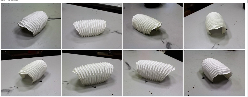
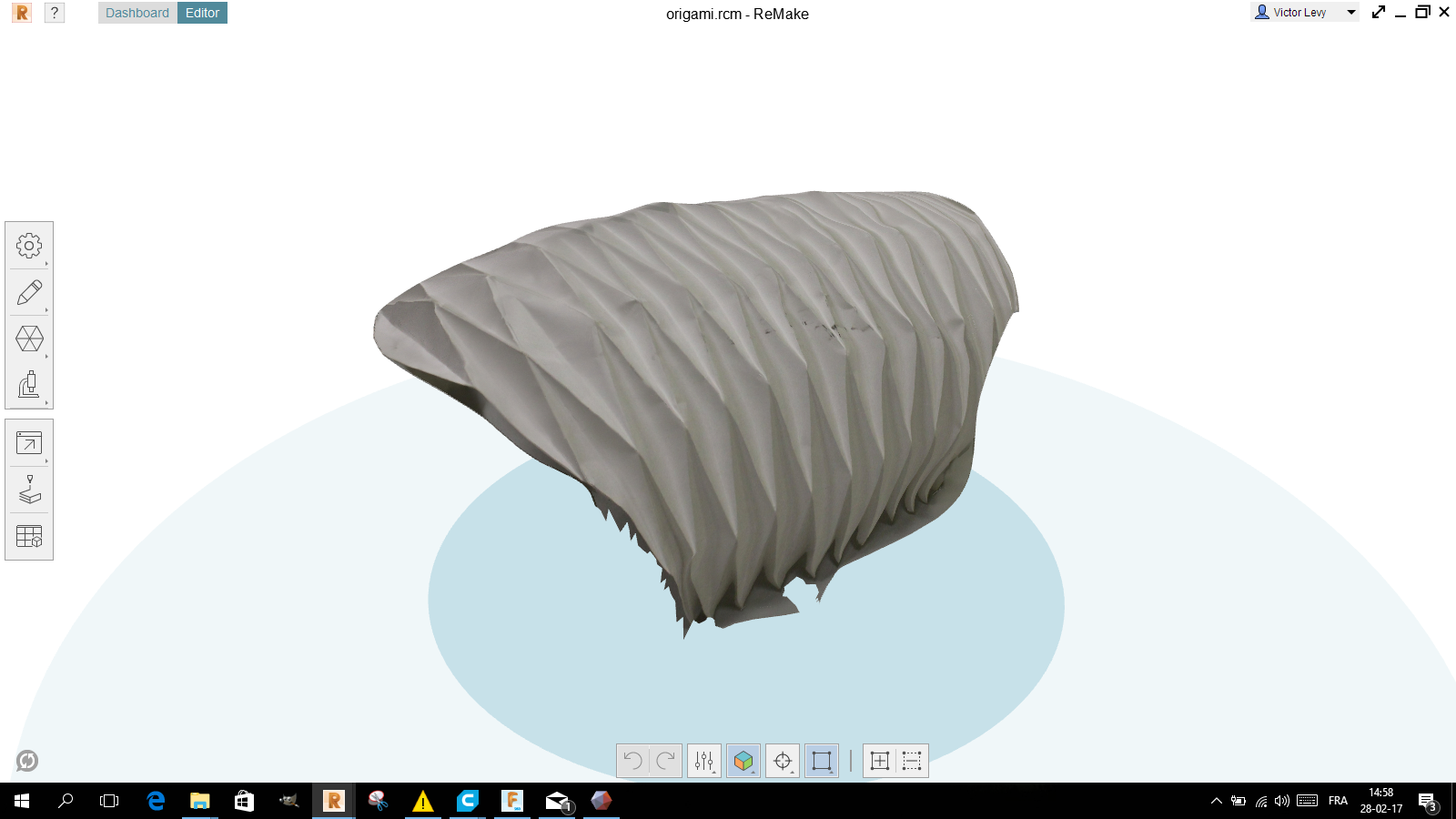
The result was not what I expected, probably because I made the images around a rectangular table,
which changed the distances between the camera and the model.
The light conditions were different depending on the faces.
3D SCANNING WITH NEXT ENGINE SCANNER
Denis has a next engine scanner in his lab that he told me about.
So I decided to test it to see the difference with photogrammetry.
I wanted to test a dark object, which is often problematic.
So I chose to scan a computer mouse.
The next engine scanner consists of a turntable with an adjustable system.
It fixes the objects to be scanned and the scanner part in which a camera and a laser part is integrated.

The laser part uses triangulation.
A laser beam is sent onto the object, and a receiver receives light reflected on a sensor.
The angle is measured by the position of receiving light on the sensor.
This explains why this type of device works very poorly with dark and absorbent surfaces.
The laser beam is then little or not reflected.
The scanner works with a software:Scan Studio HD .
First you have to install the object to be scanned.
This screenshot shows how I positioned it ...
It would have been better for the scan of the mouse to install it vertically to have the maximum of visible faces.
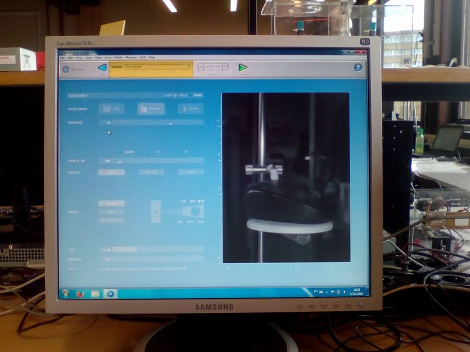
When scanning, you must also specify several things:
The number of images:
this will give somehow the resolution of the scan.
I chose to do 6 images.
The type of surface of the object.
I chose dark, since the mouse is black.
Once this is done, the scanner rotates the object on the board 1/16 of a turn,
scans with the laser and takes an image.
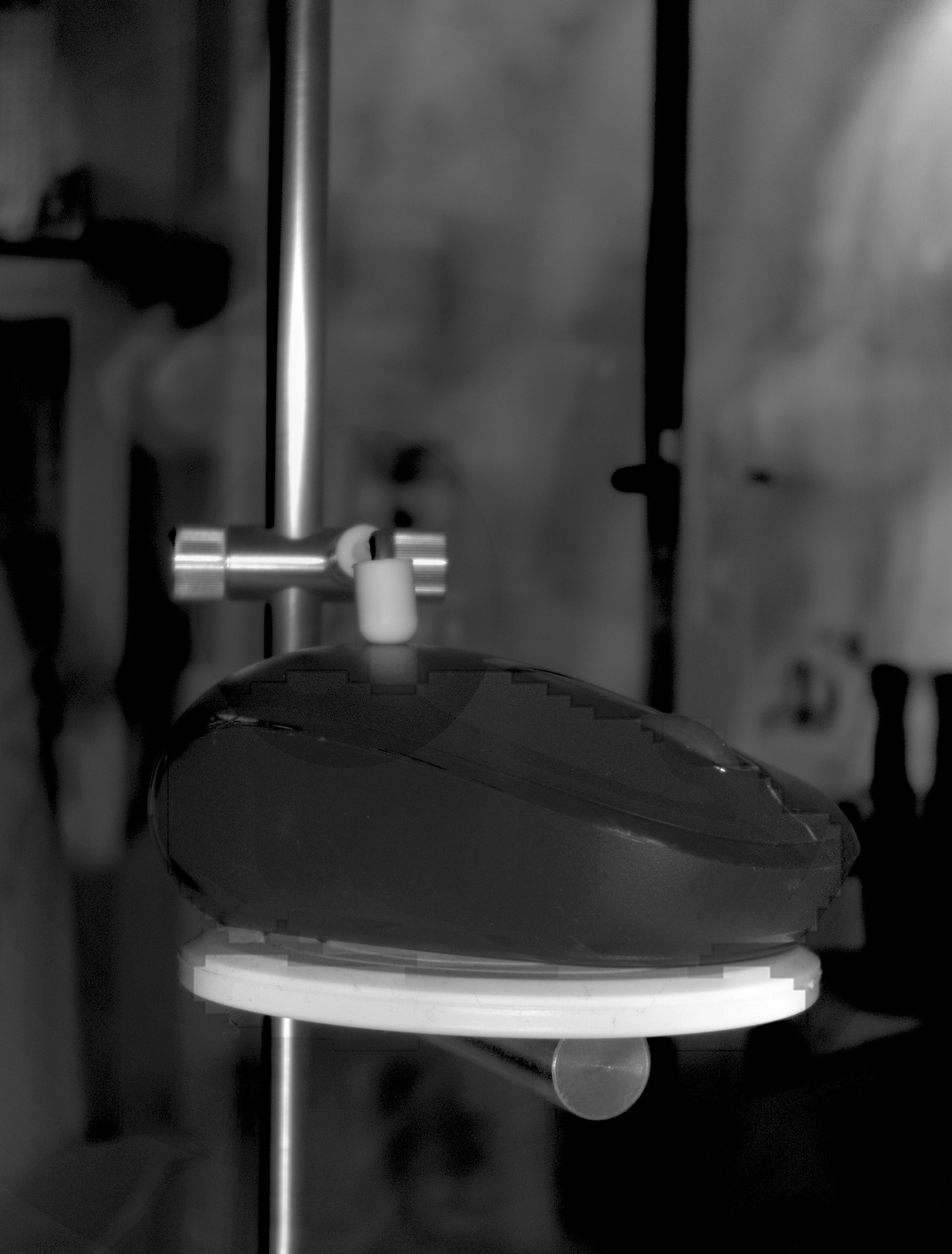
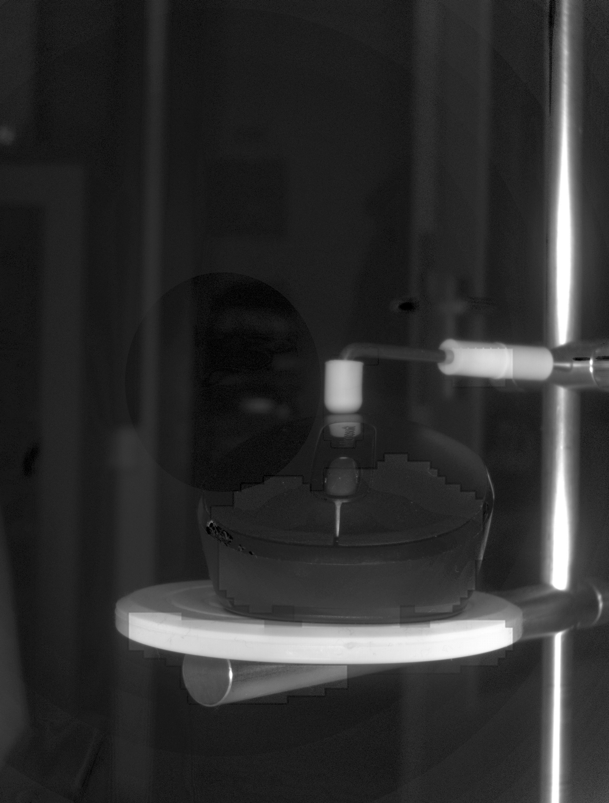
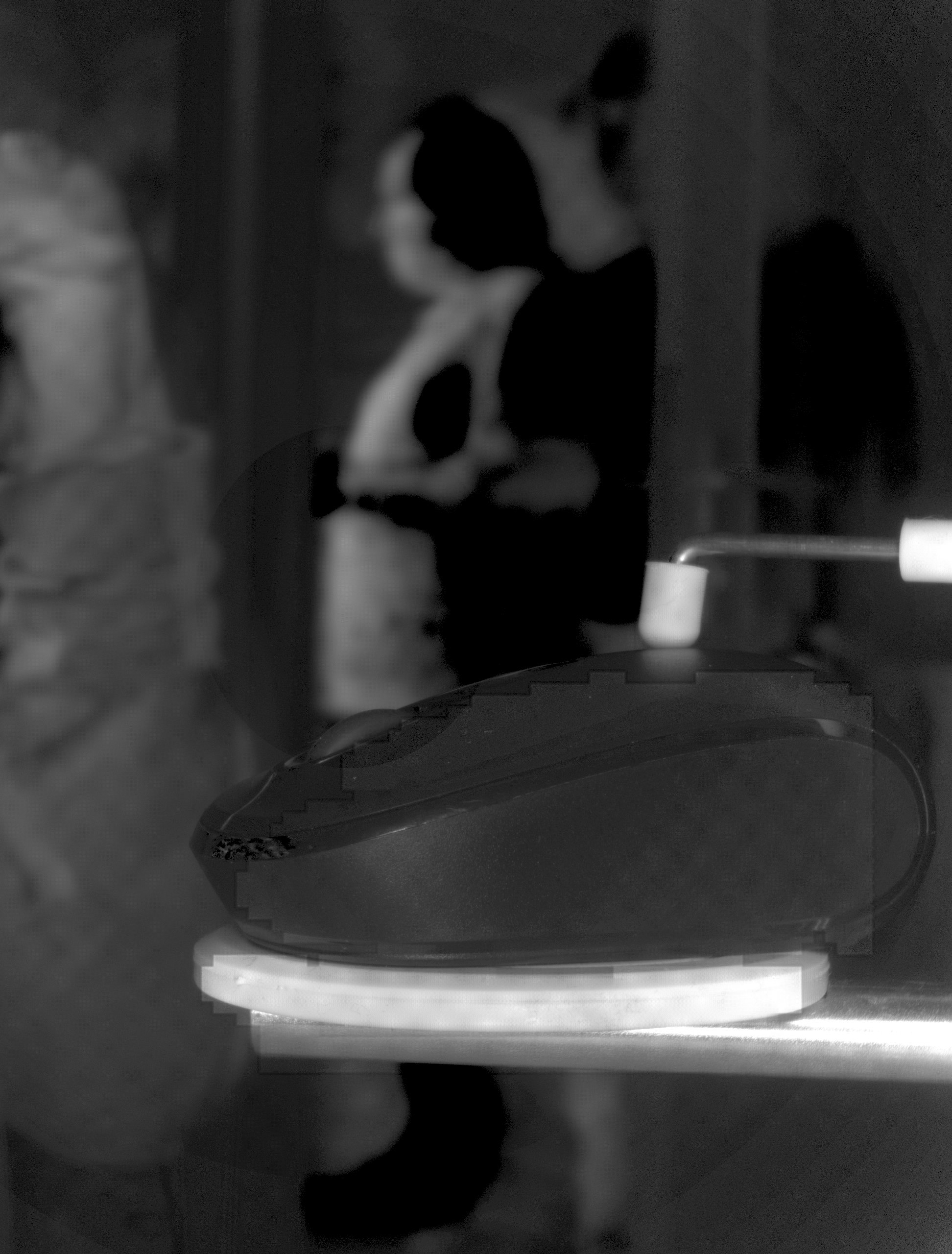
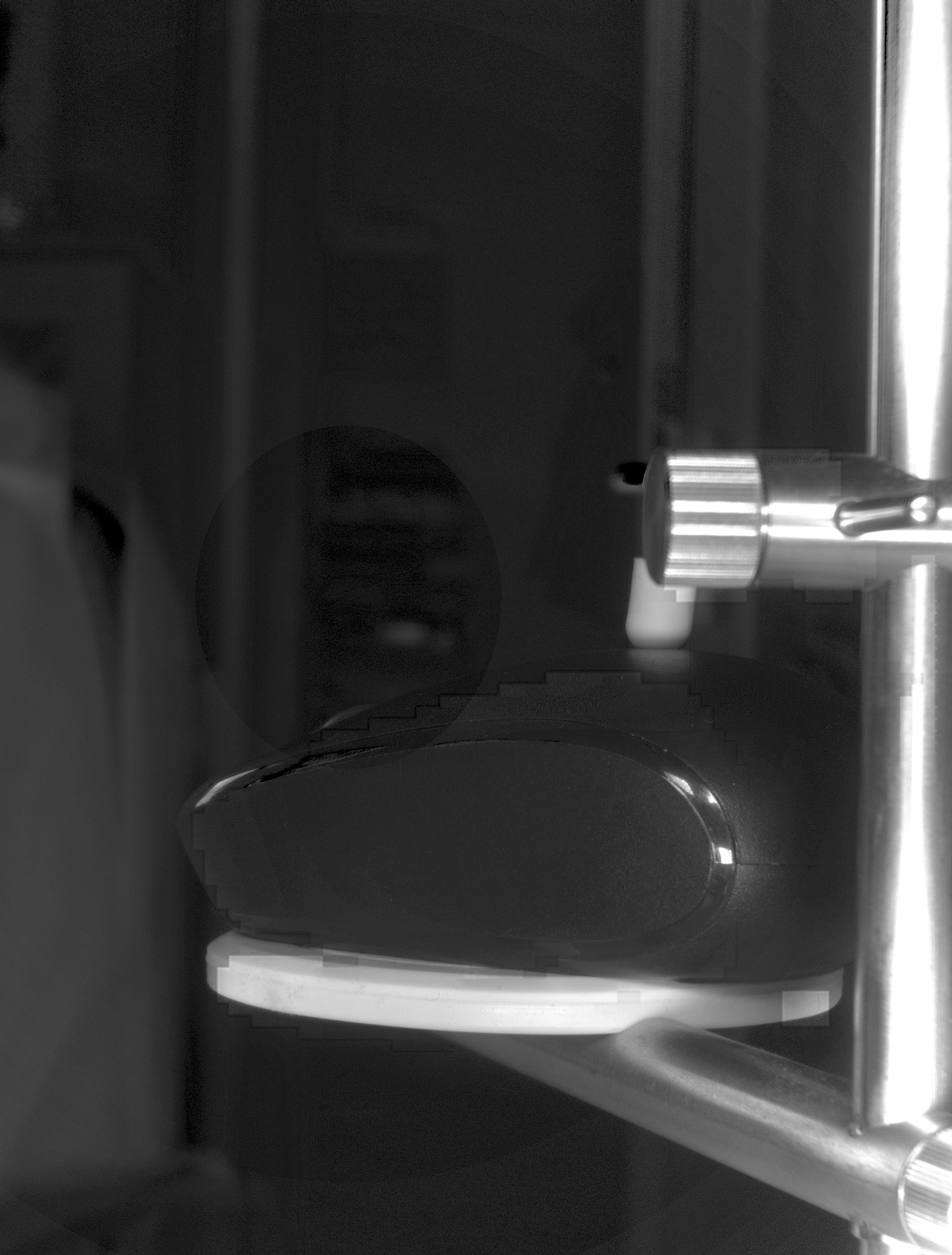
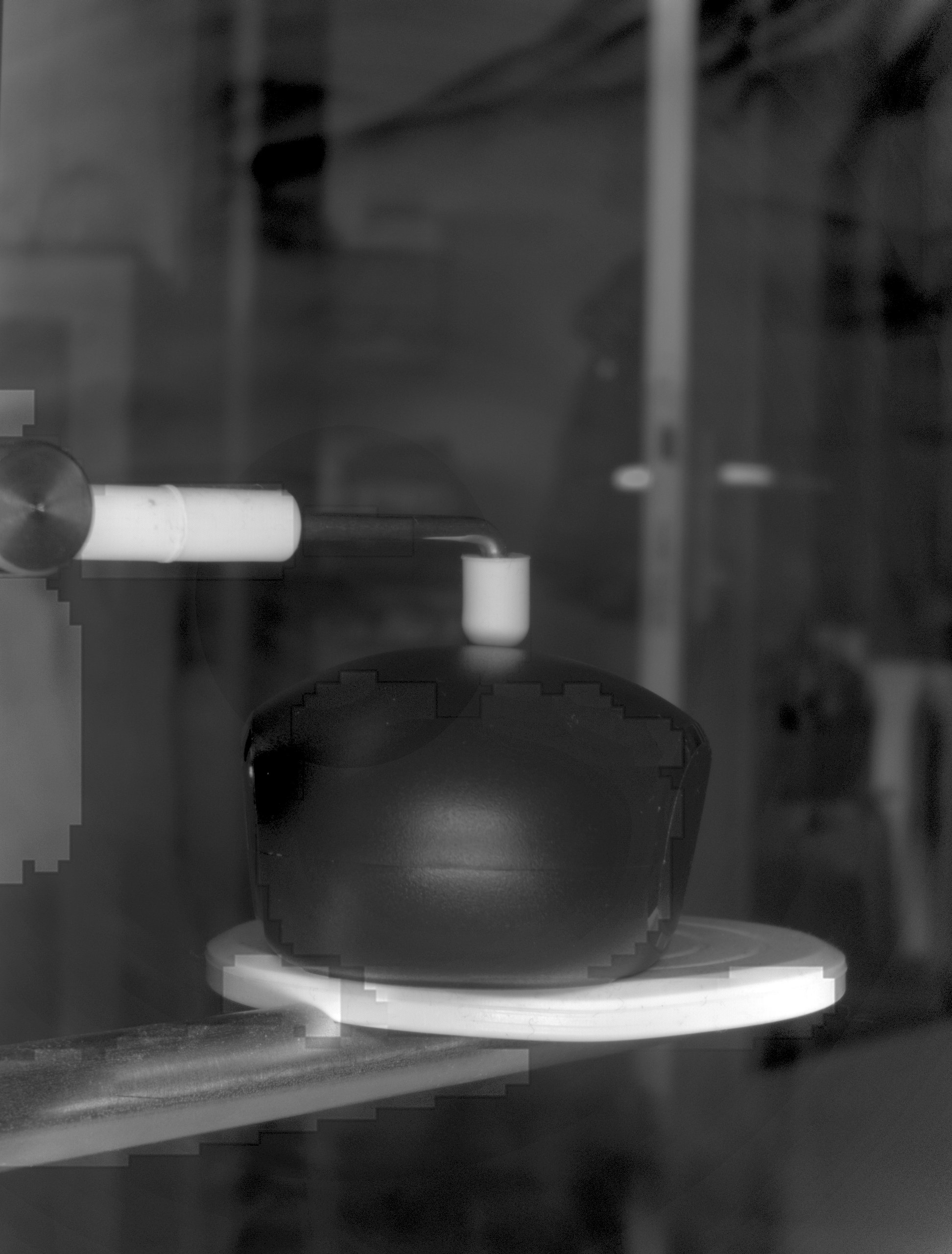
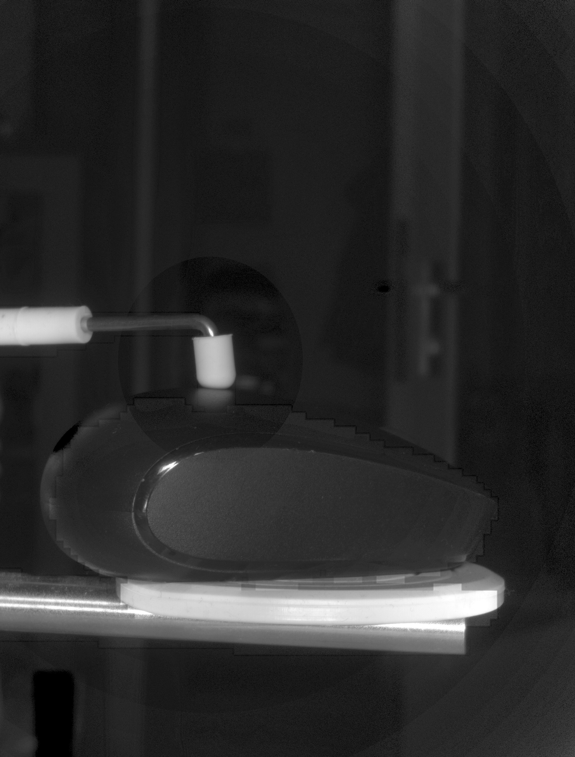
After about twenty minutes the scan was finished.
I used meshmixer to correct the holes left by the scanner in the 3D model at the fixing locations on the tray.
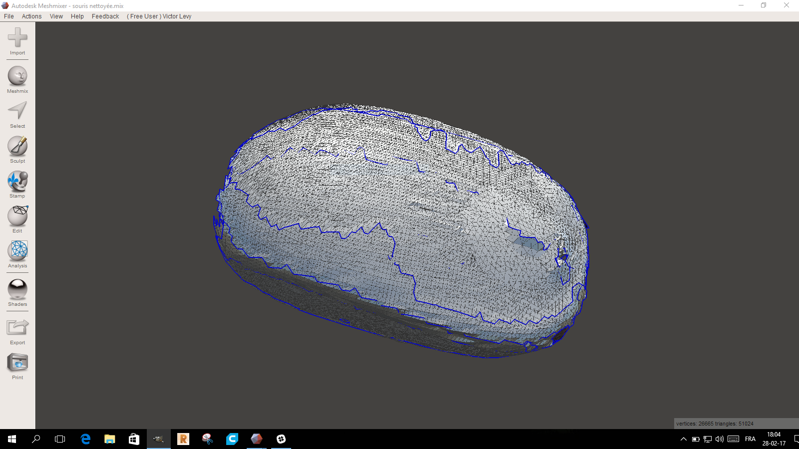
After that, I used Meshmixer to correct the holes left by the scan.
It was impossible to correct the two end of the mouse
3D PRINTING FROM FILE
I tested a form wich needed bridges, supports to see how this was working. I made it on fusion 360.
I designed this form because it is impossible to produce it on another machine.
With a 3 axis CNC milling machine you could not do it.
You could not enter with the tools inside the form.
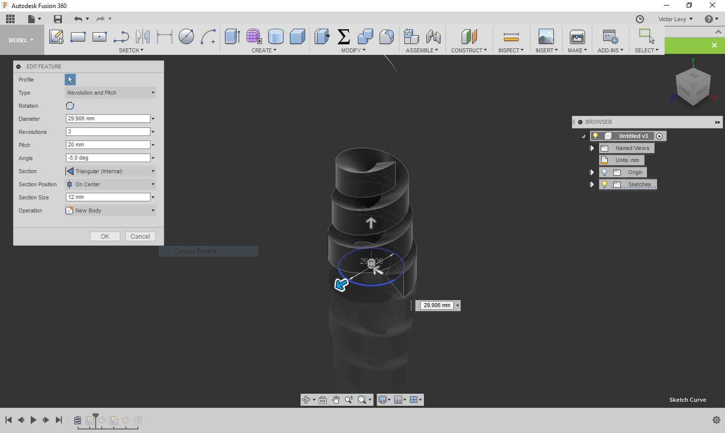
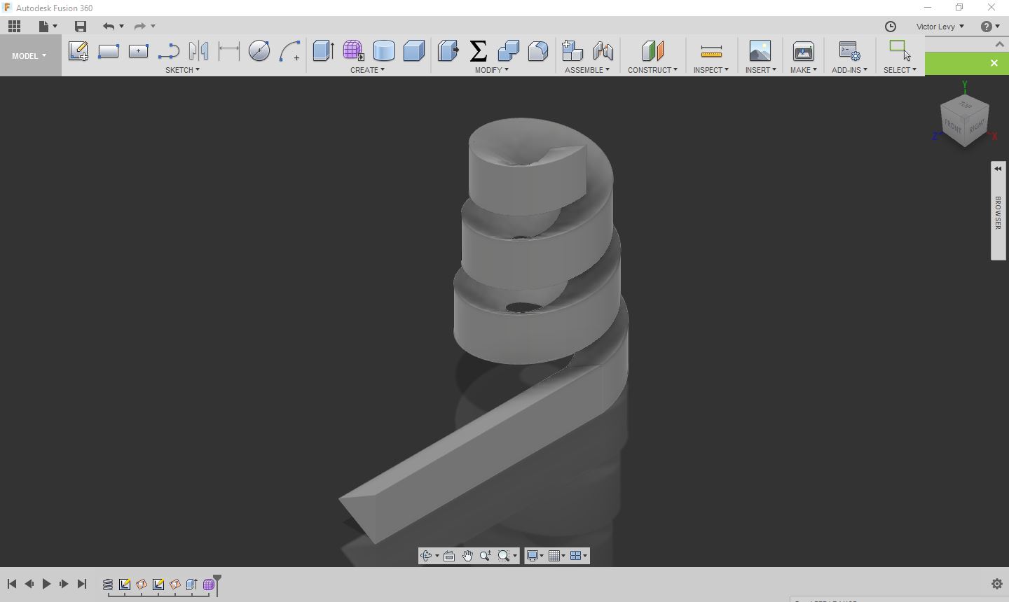
I designed a coil with a triangular section and a decreasing diametre
and added a horizontal volume to it.
I exported it in STL format and opened it on Cura

It was printed on our Ultimaker 2+
Print settings:
- Subject: PLA
- Height of the layers: 0,25mm
- Filling: 60 pc
- Brim: Yes
- Supports: Yes
- Speed: 50 mm / sec
- Cooling: Yes 100 pc
- Temperature: 200 degree C
- Print time: 2 h 50
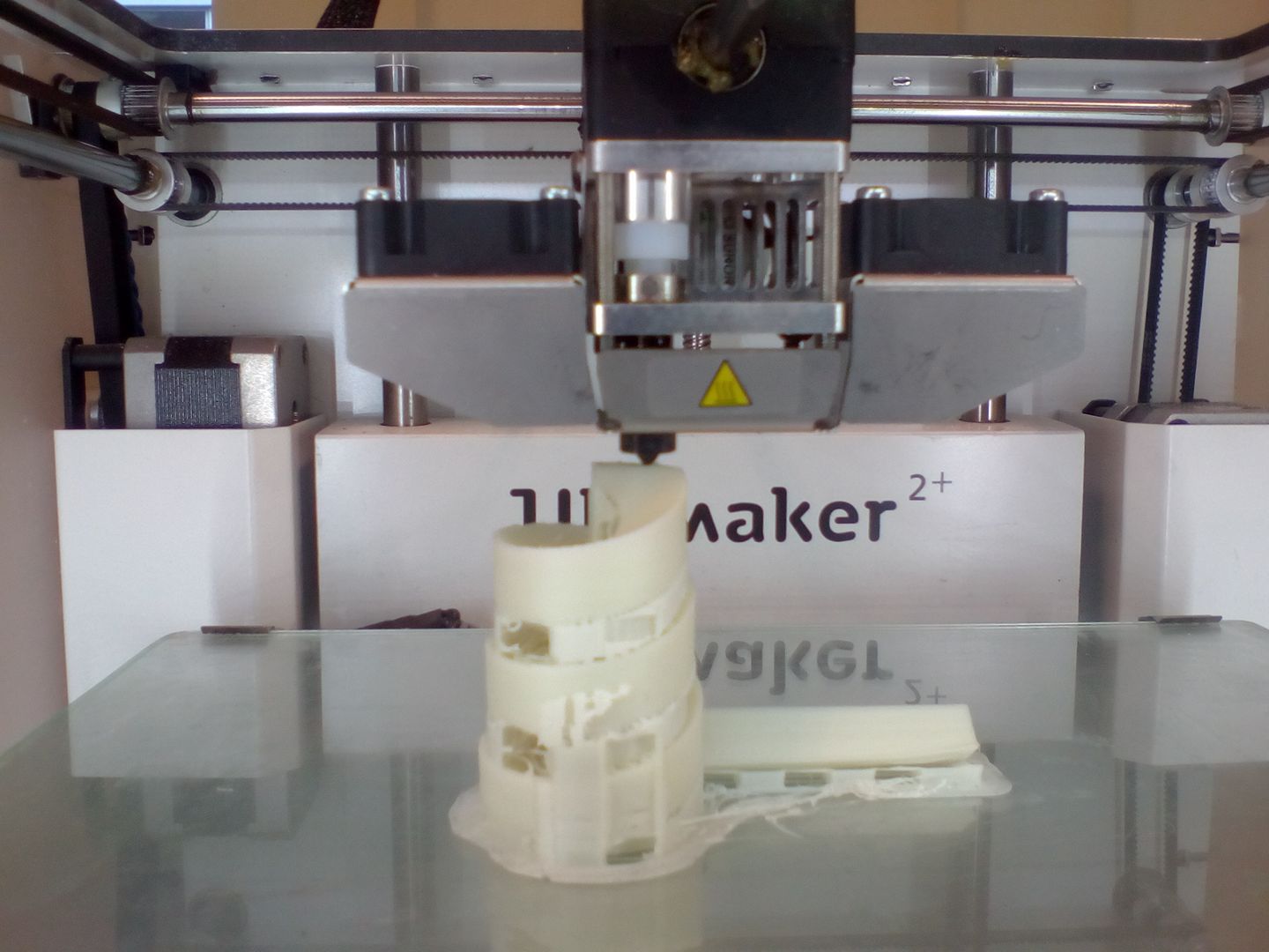
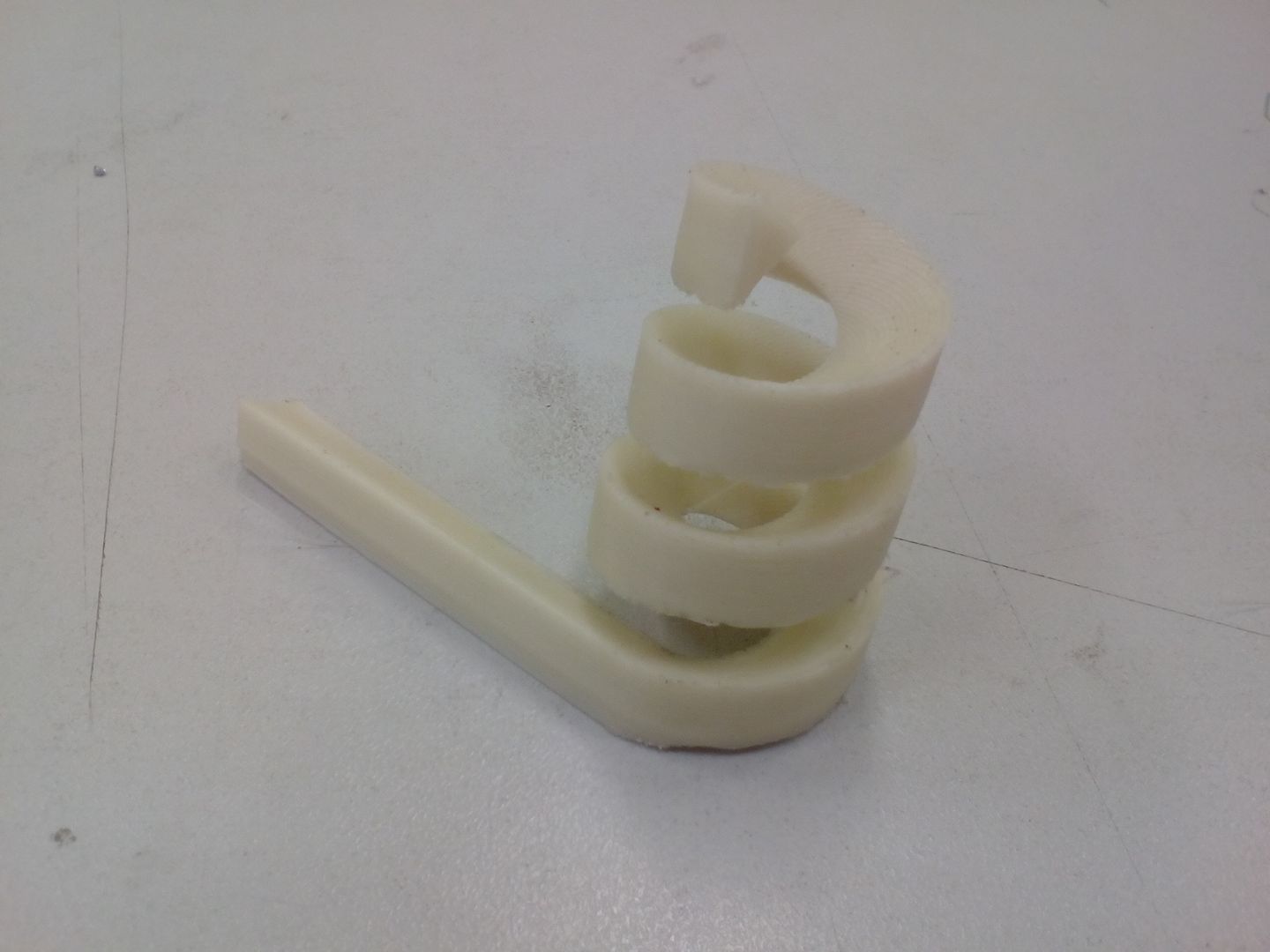
Here is the final result without after removing the bridges.
HOME