Computed controlled cutting
week 4
- Make lasercutter test part(s) varying slot dimensions using parametric functions
- testing your laser kerf and cutting settings (group project)
- cut something on the vinylcutter, design, make,
- and document a parametric press-fit construction kit,
- accounting for the lasercutter kerf, which can be assembled in multiple ways
SOFTWARE USED
- Fusion 360
- Inkskape
- Esay cut studio
- Smartcarve
FILES
Press fit Kit
Press fit Kit parametric fusion 360
Sticker Saint Valentin easycut studio
Saint Valentin svg
GROUP ASSIGNEMENT
laser cutter group page
LEARNING EXPERIENCE
This week I learned to make a parametric design
I learned how to test and use our laser cutter, a Cyborg LS 1080-K
We tested with Nicolas, my labmate the kerf of the laser
We also tested and used our Roland GS 24
TESTING THE KERF OF LASERCUTTER
The laser of a lasercutter burns away a portion of material when it cuts through
It is the laser kerf.
This week's assignment is to test and find the value of the kerf on our machine.
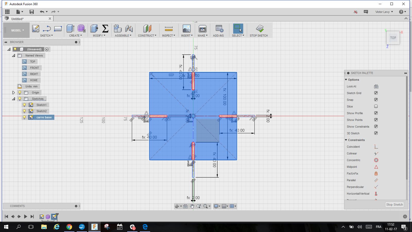
To make the parametric joints, I had to go back to learn better the sketch mode in Fusion 360
The function used is : rectangular patern
to duplicate and Offset to enlarge a form
I used some shortcuts with mouse to speed up designing,
move/copy 2D and 3D, rotate ...
I made parametric using the parametric tab in the modify menu
in thickness, length of joints and side of the press fit kit.
I made a dxf file and uploaded it on the software of the lasercutter
I tested several speed and power
The final one are : Speed 80 mm/sec, power 20 pc
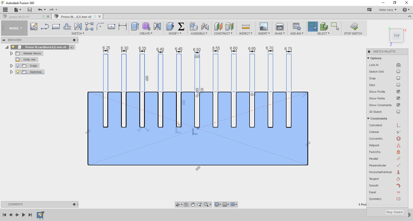
The lasercutter cuts 0,2 mm kerf inside the form
To have the cardboard with a tight join, I need to have joints of 6,0 mm for a cardboard of 6,5 mm
I started from the simplest joint showed by Neil
I made it parametric, using Fusion 360,
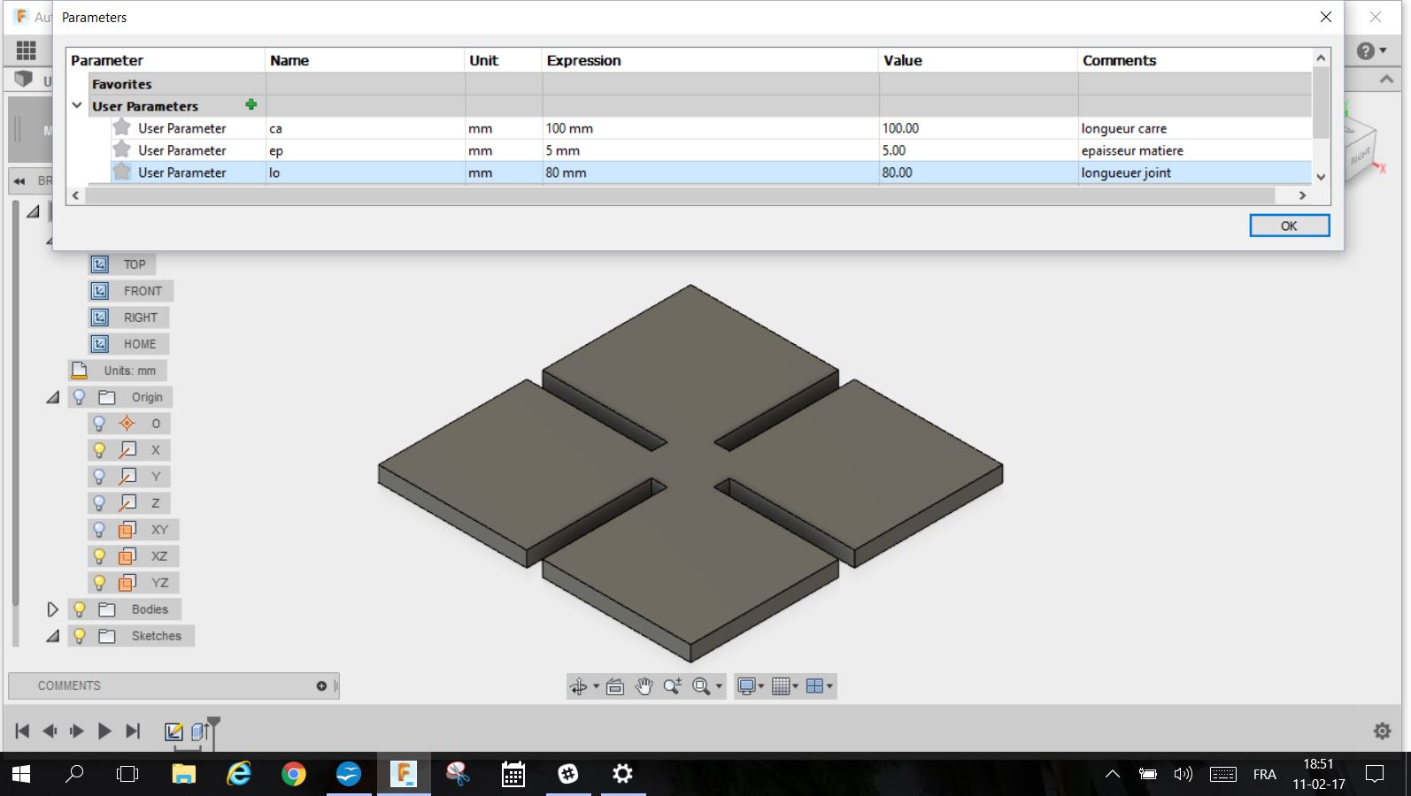
To do so, you have to go on the "Modify" menu and select "change parameters"
It opens a data sheet where you can enter parameters for different dimensions in the drawing
In the data sheet, you enter the name of the dimension and the value.
You can change it and it will change every value with the same name with the dimension changed.
Then I extrude the sketch using the "extrude"function in the "Create" menu
I also made a second type of joints with round edges
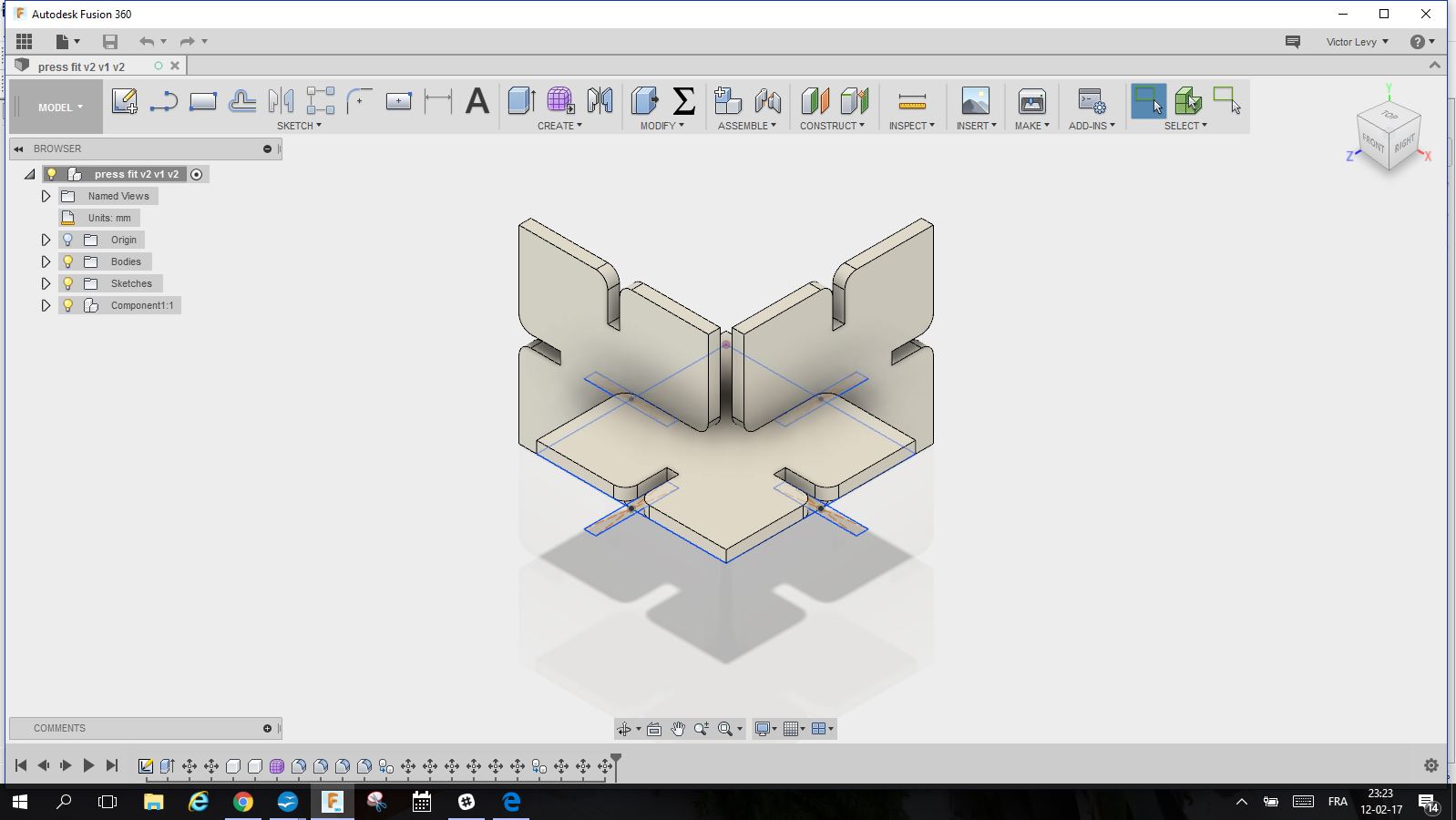
PRESS FIT KIT
I decided to make a very simple kit, just circles in cardboard with parametric joints and possibility to cage the thickness of the material.
I discovered new functions and clarified the difference between sketch, bodies, construction ...
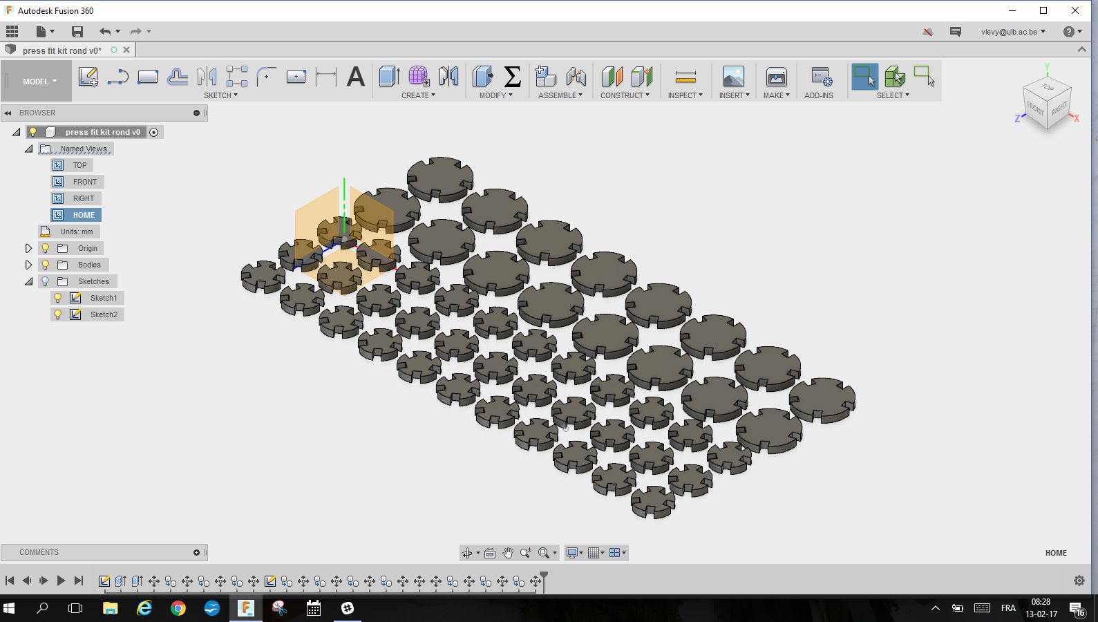
I also checked to see if parametric design worked.

A DXF was needed to cut on the lasercutter
then I went in the "Sketch" menu and selected "Project" to generate a dxf on the plane of the bodies
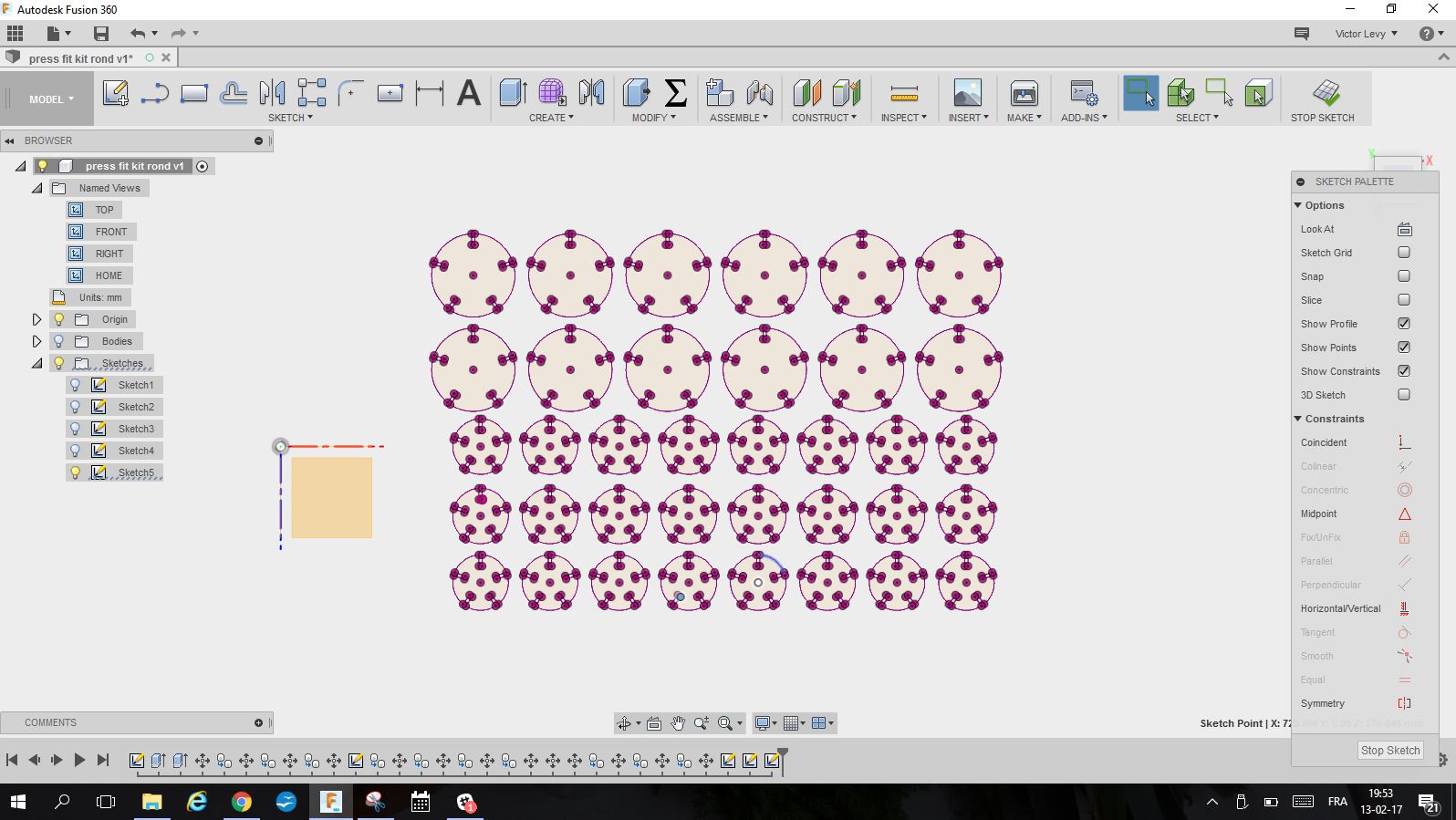
Once the documents saved in DXF, I opened it on the computer that drives the laser cutter.
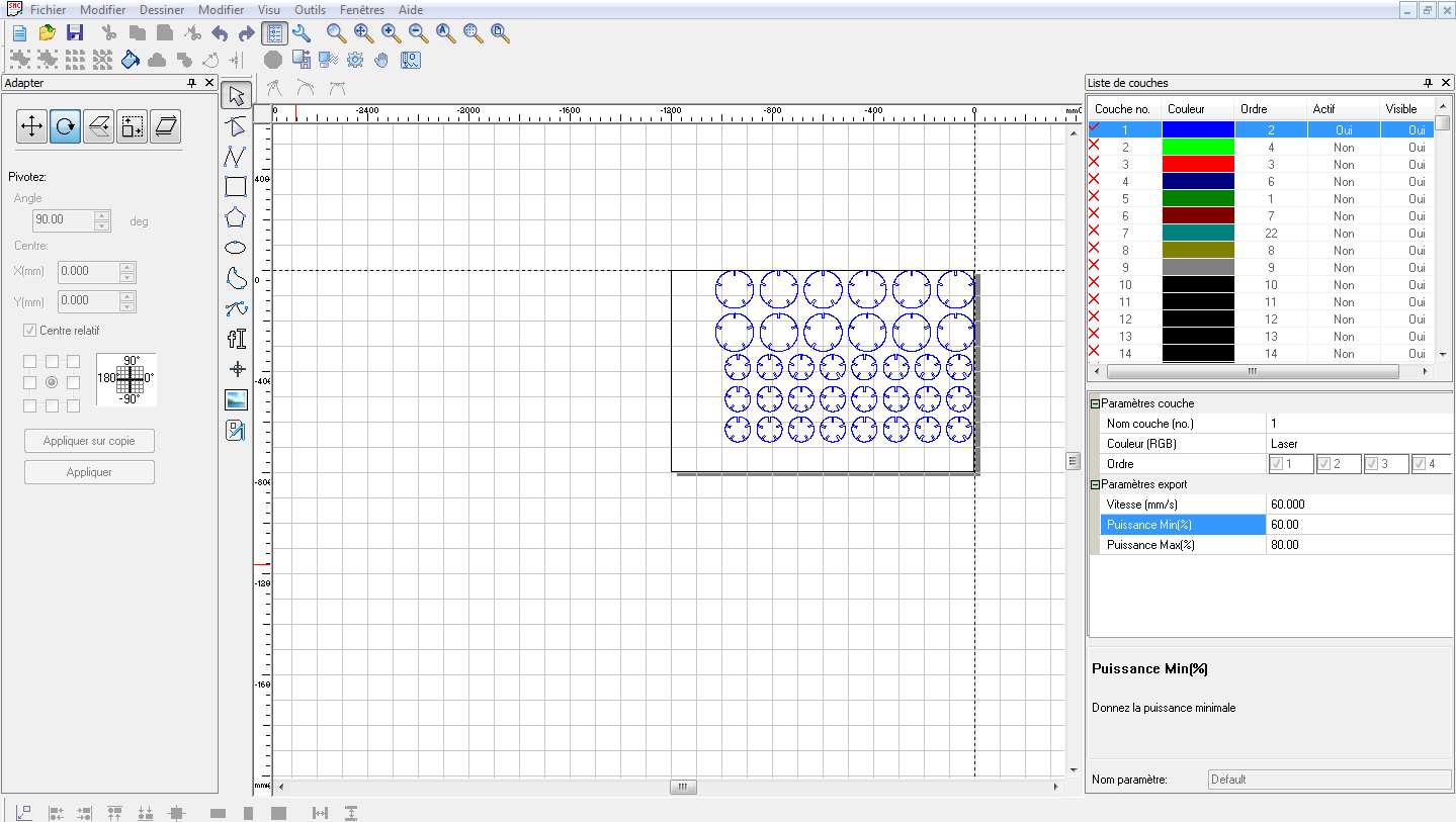
The easy cut studio program imports DXF and AI vector formats.
This program allows you to do simple operations such as:
scaling, designing some basic forms, optimization of the laser path for example.
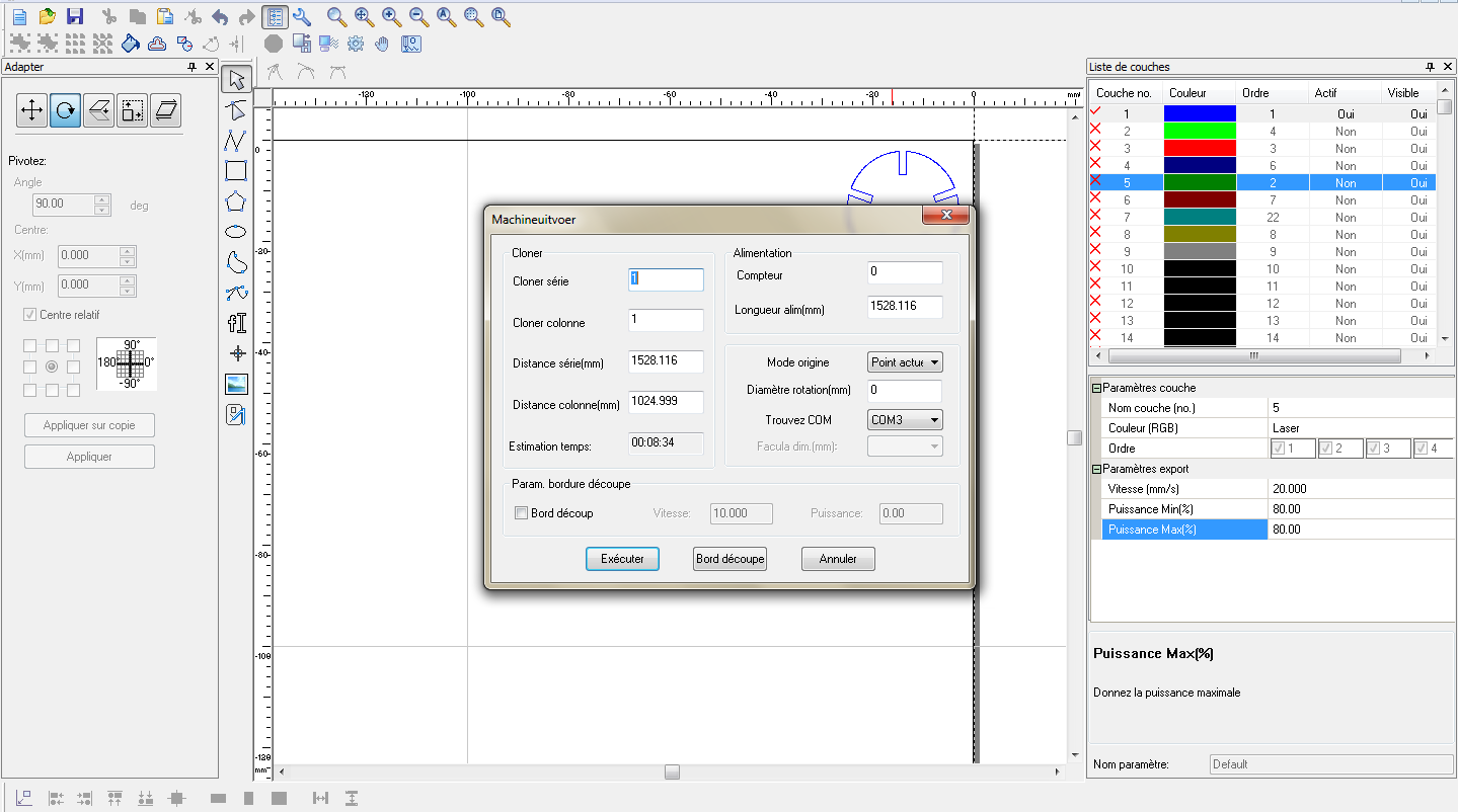
There are layers to be able to work with different parameters, for exple if you cut and engrave one board.
You will use 2 layers.
It also makes it possible to adjust the speed of movement of the head with the lens and the power of the laser.
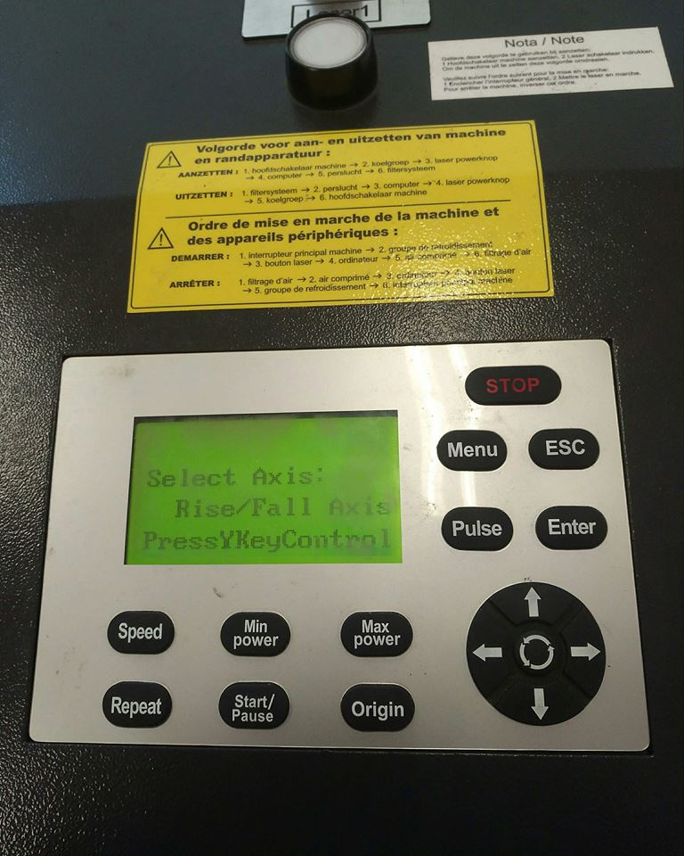
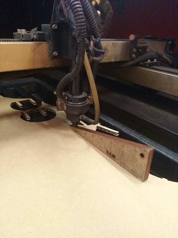
The steps for cutting are as follows:
Adjustment of the focal point height of the laser, here 8 mm.
This is done using a menu shown on the image.
Adjustment of power and speed in the software;
Here I made two tests
60 mm / sec, 60 pc
80 mm / sec, 60 pc
Then start the cutting
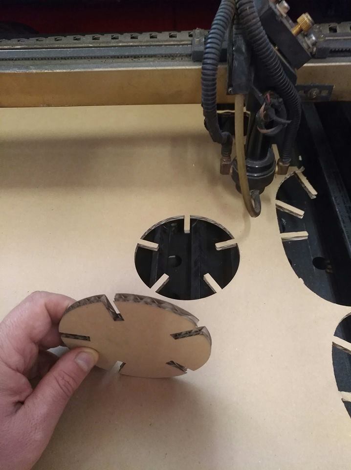
The best for this triple layer cartboard is the 80 mm sec, 60 pc.
The edges are perfect and little burned.
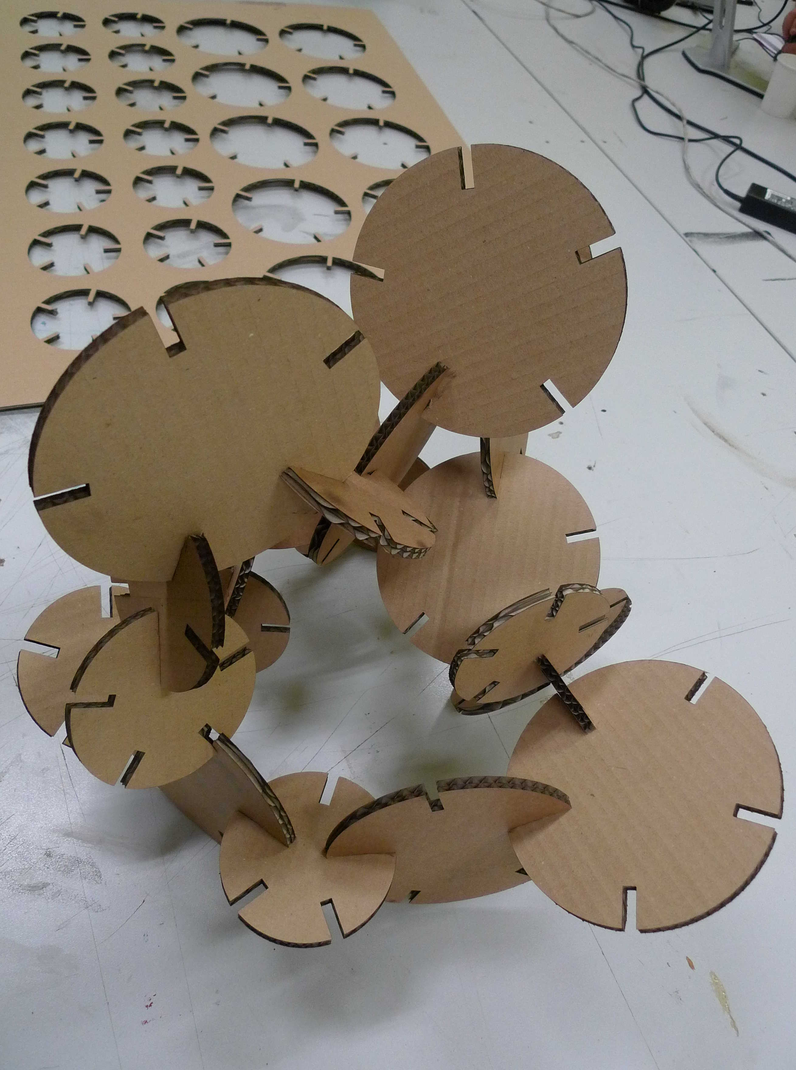
This is the result after laser cutting
VINYL CUTTING
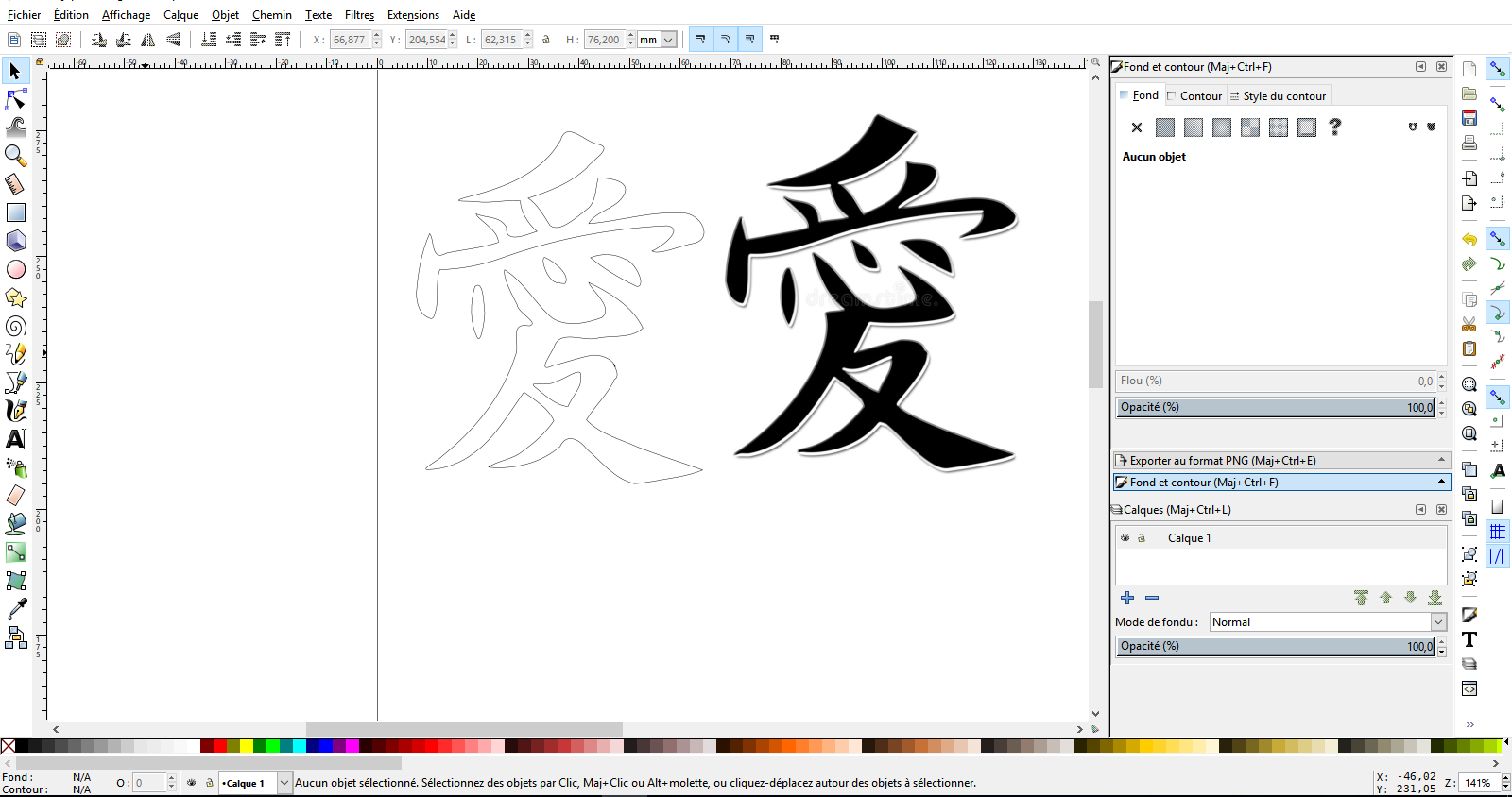
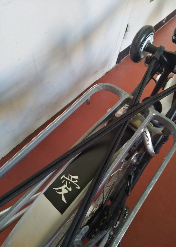
For this week assignment I decided to make a sticker for Anne's and my bikes for Valentine's day
I searched for the japanese ideogram for love and transform it into a vector image using
inskape
I did it in going in the Path menu and using "trace bitmap"
Exported in SVG format
Then I installed easy cut studio from the website of Roland
Imported the SVG image in the software
I connected the computer to the Vinyl cutter
Placed the vinyl sheet and blocked the metal pieces behind the machine to hold the vynil
I used a small sheet to make the test
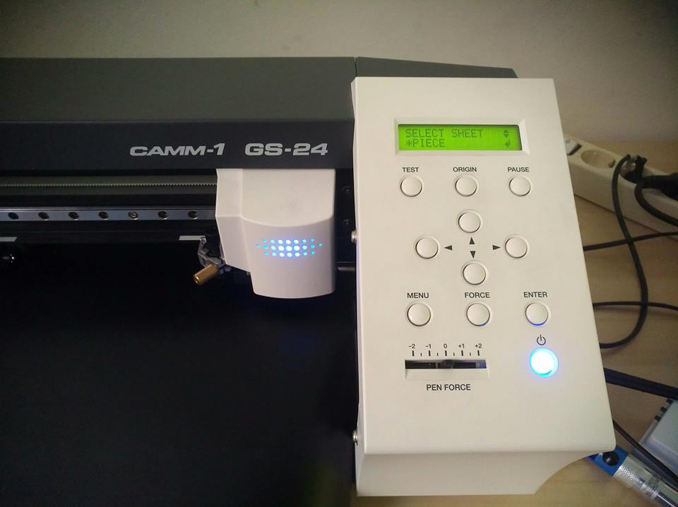
The sheet must be between 2 white lines
You have to choose between 3 mode in the select sheet menu : roll, edge , piece.
I choose "Piece"
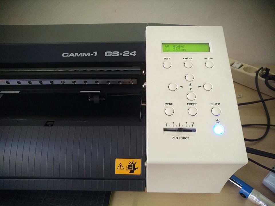
The machine recognize the size of the paper
I change the settings of the page setup in easycut studio
To fit the paper size detected by the machine
I placed the drawing on the page
! Pay attention to the orientation of the paper
The origin of the cutter is on the image below, it is down and left
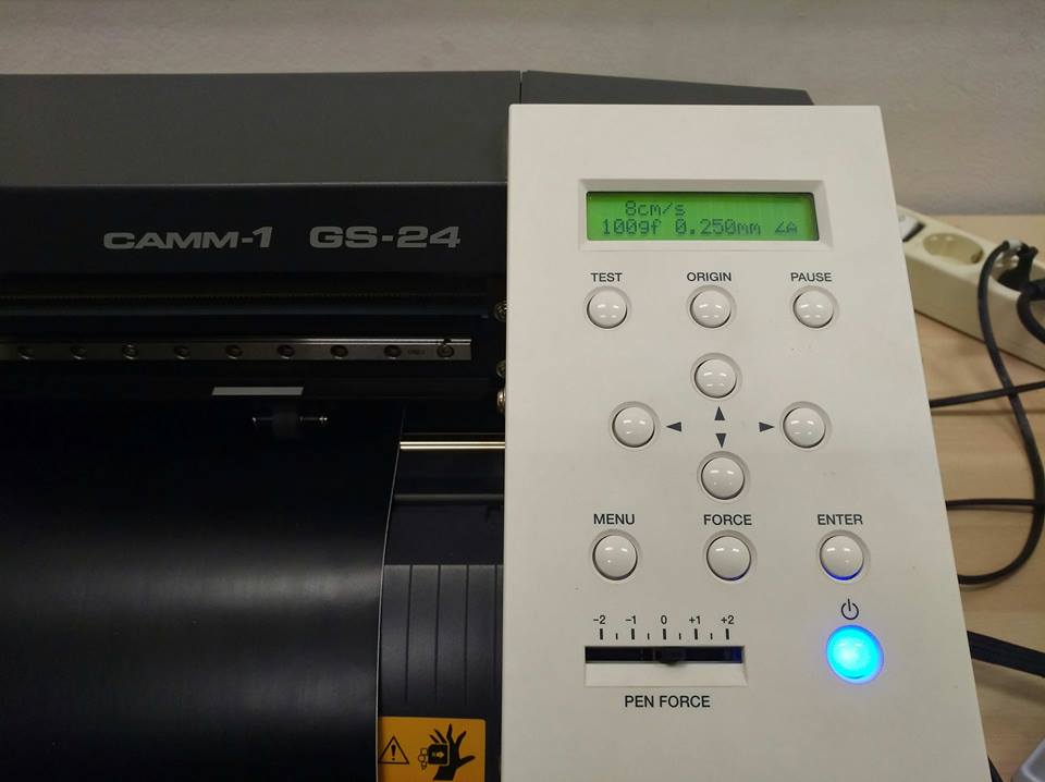
I put also value for the pressure of the tool at 90 gr and after test at 110 gr
and tested several speed: 8cm/sec, 5cm/sec and 2 cm/sec
The value can be changed on the mac
There was no difference between 5 and 2 cm/sec,at 8cm/sec there was a problem of cutting
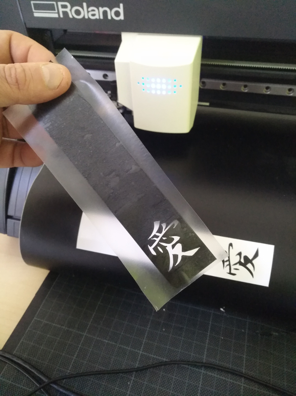
Then cut
I cut a sheet of the transparent vinyl to place on the black vinyl to hold the small pieces
Glued it of the roll
And placed it on the bike
and it all done ...
HOME