characterize the specifications of your PCB production process.
PCB production process
Week 1 goal :
characterize your lasercutter, making test part(s) that vary cutting settings and dimensions
A Basic Panel
Assignment
Characterize the specifications of your PCB production process.
Our CNC milling machine
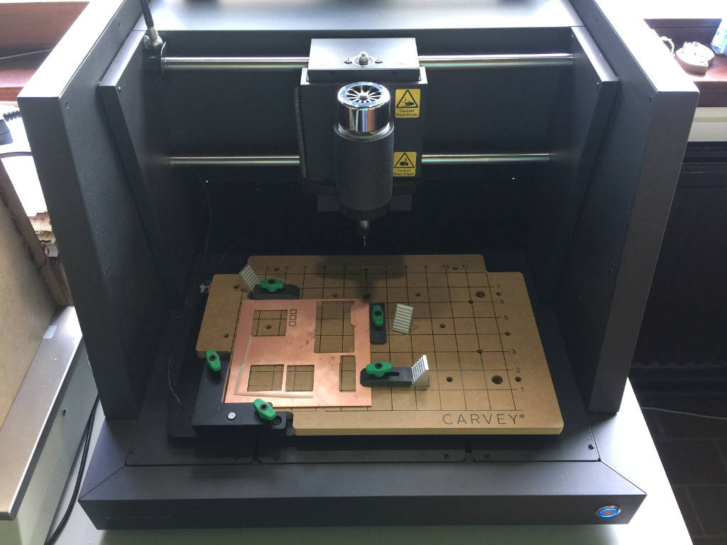
To mill our PCB we use a Carvey milling machine from Inventables. The user interface of this machine is called Easel and is an online software.
The Carvey CNC milling machine.
Preparing the file to mill on Easel
From PNG to SVG, using Inkscape
Open inkscape
import the png image to mill in a new document.
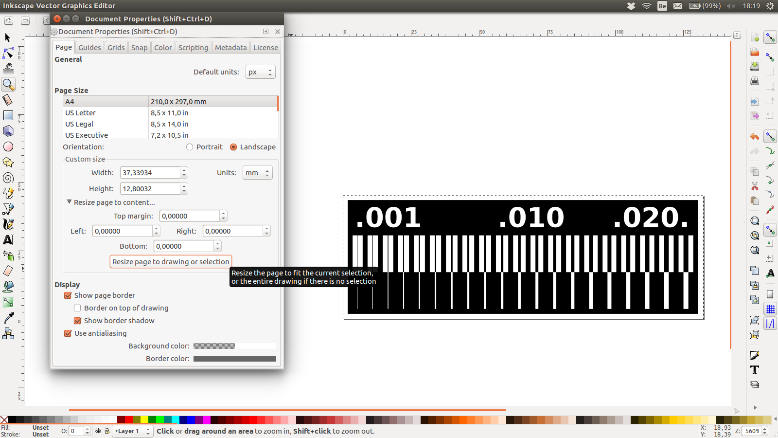
resize the page to fit the imported image
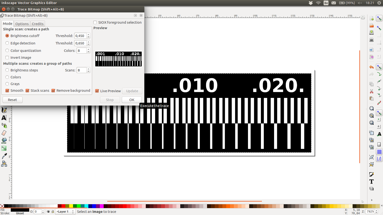
To vectorize the contour of the black and white image, open the Trace Bitmap panel and make the trace.
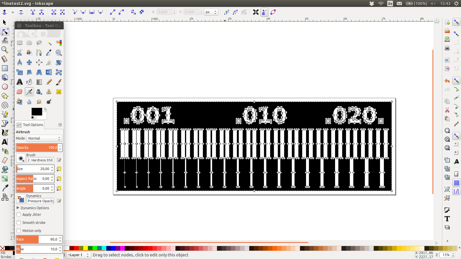
Export the image as a SVG image.
Resize the page to the selected image (PCB).
Make the trace from the bitmap image.
Here is the trace ready to be exported as a SVG.
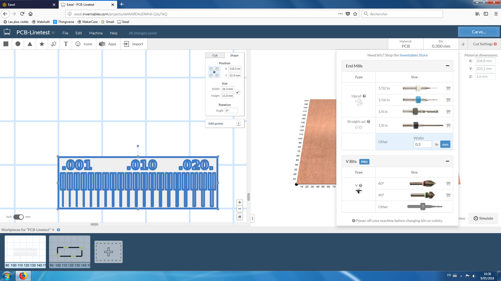
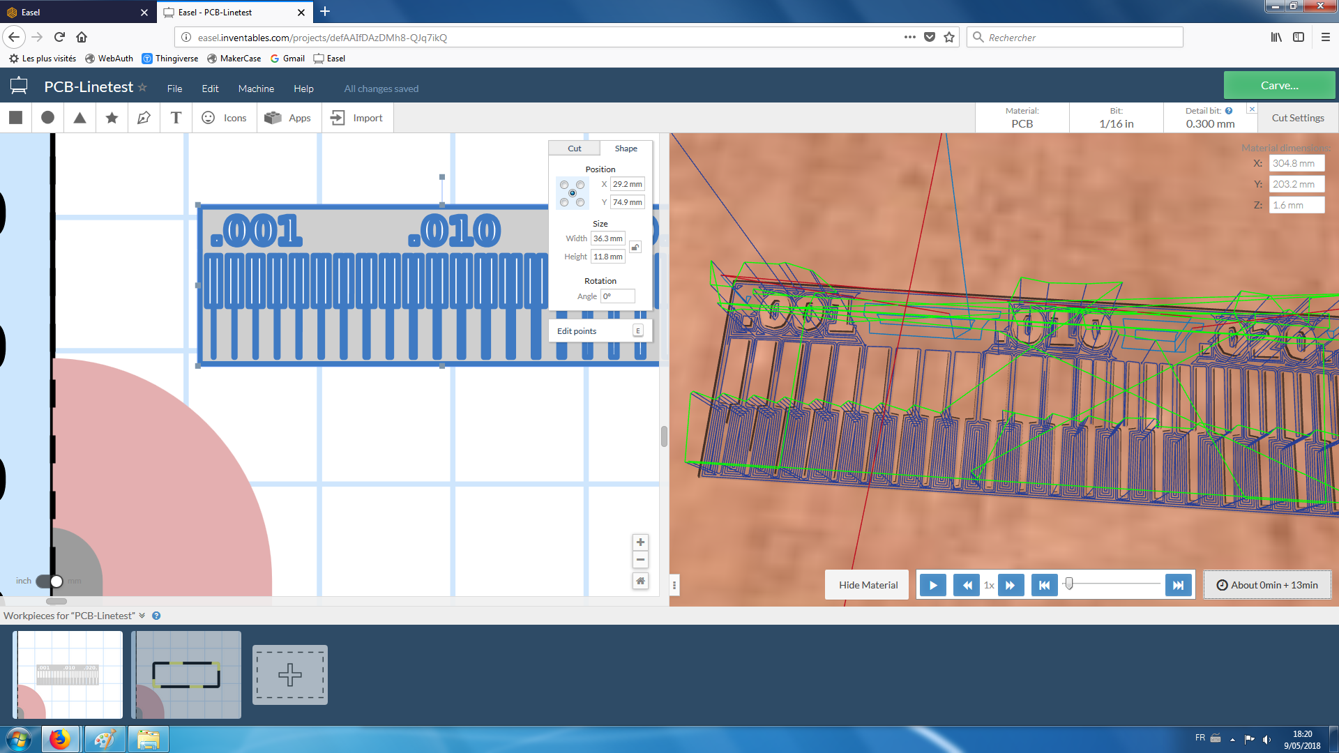
The Easel interface
The Carvey CNC milling machine user interface is called Easel. Using Easel it is possible to import directly a png image to mill, but Easel do a terrible job at tracing the contour of the bitmap image. So we import SVG image that Easel can manage more easily. The interface is quite user friendly.
The Easel software interface.
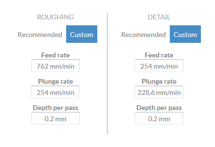
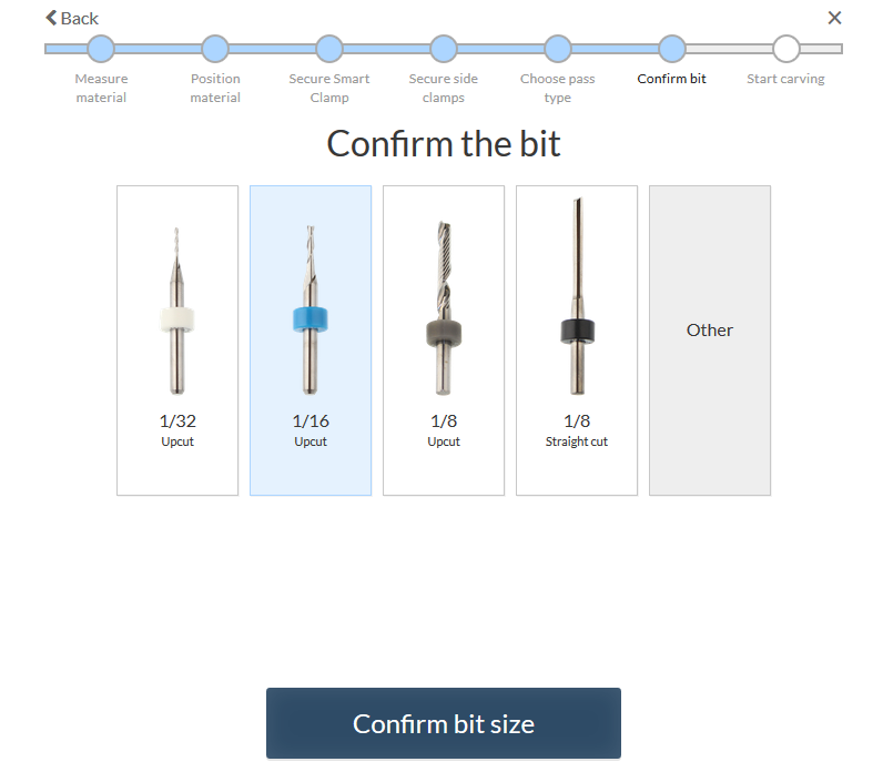
Settings the milling parameters.
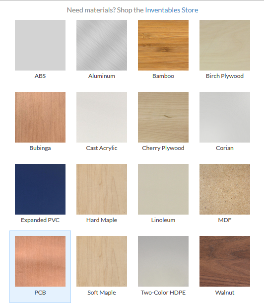
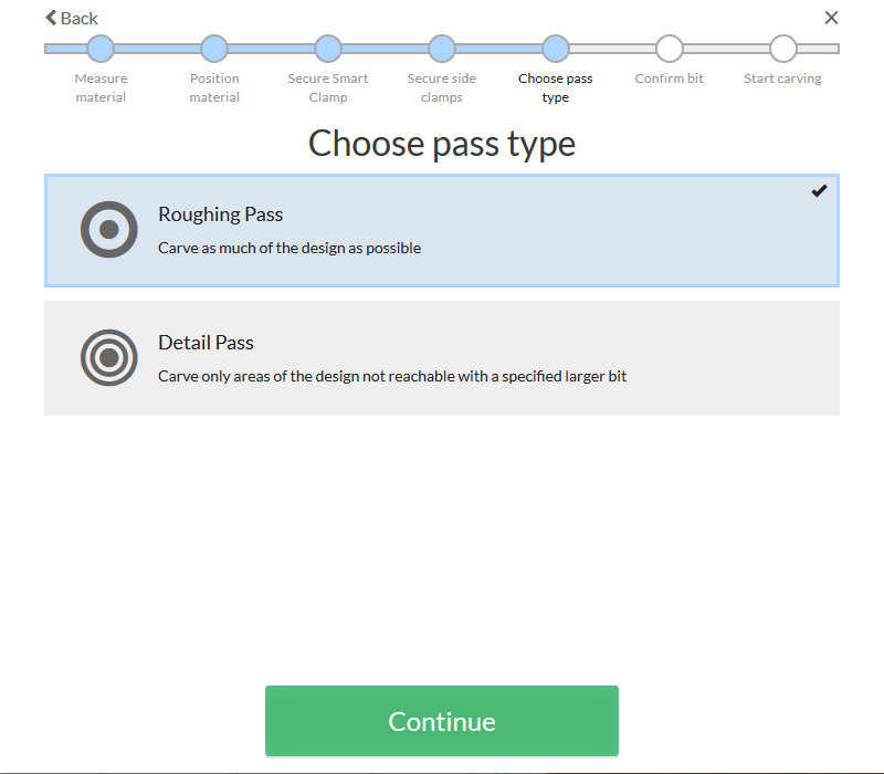
Choose the material (PCB).
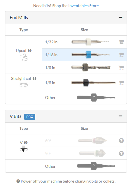
Choose the roughing bit type (1/32 In).
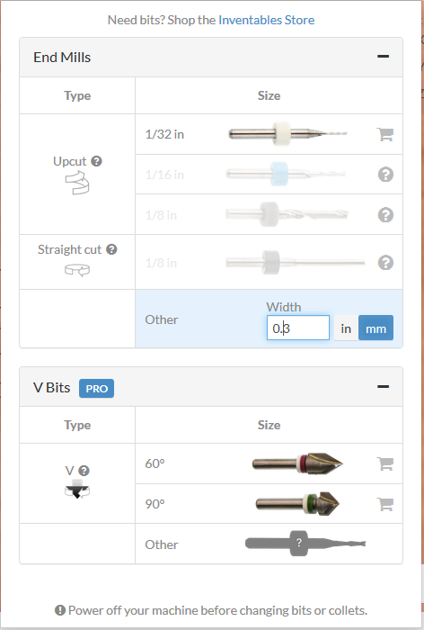
Choose the detail bit type. We selected "Other" with a width of 0.3 mm. In fact we use a V-shaped bit that we estimated at 0.3mm of width when milling at a depth of 0.1 mm.
Then we let the cut settings at the default values.
Simulating the toolpath.
Before sending the job to the CNC milling machine, we simulated the operation on Easel to visualize the toolpath.
Preparing the CNC milling machine
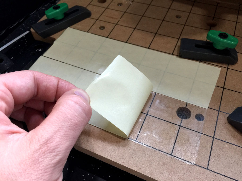
Trouble shooting the z-axis error of the machine..
Our carvey has an annoying problem that we have not yet solved. The zeroing of the machine on the z-axis is not good.
We sometimes have an offset of 0.5 mm which is a problem. This problem is even more annoying when using V-shaped bits.
The trick we have momentarily found is to add a spacer of 0.5 mm (the white stripe on the image below) in between our material and the smart clamp of the CNC. Then, we mill our board by iteration of 0.1 mm in depth until we mill the copper.
It is a problem that is discussed on the Carvey user forum but no solution have been found until now.
White spacer of 0.5mm thickness used to troubleshot the z-axis offset problem.
Setting the PCB on the CNC.
We place a double faced tape to glue the PCB on the base. It is really important to flatten the PCB.
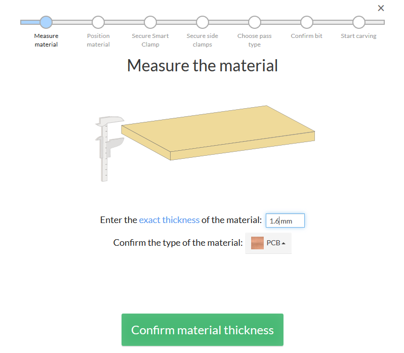
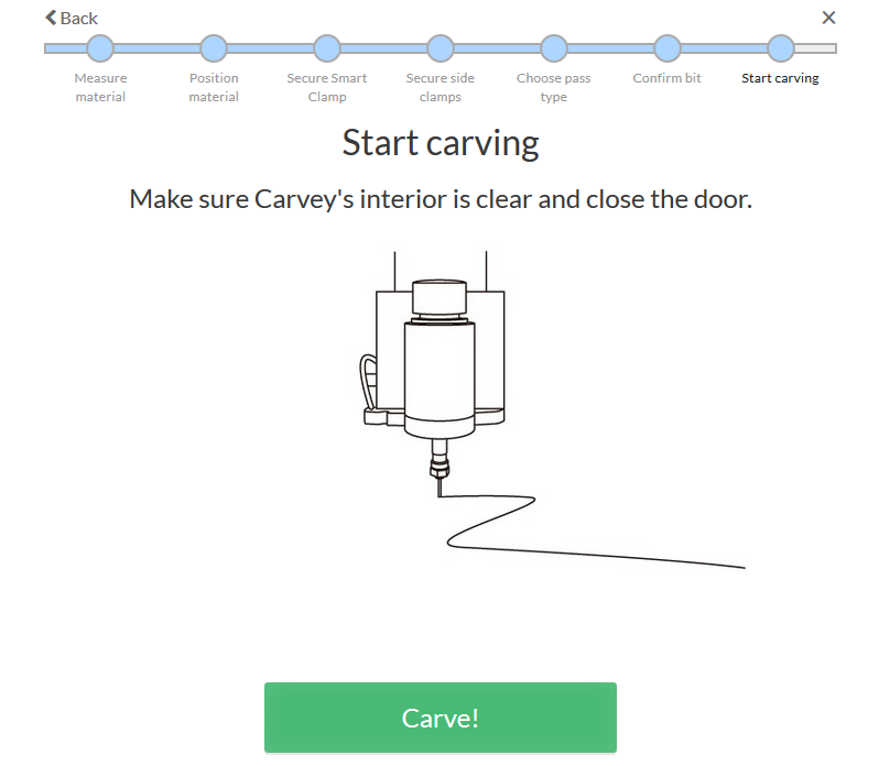
Sending the carving job to the machine.
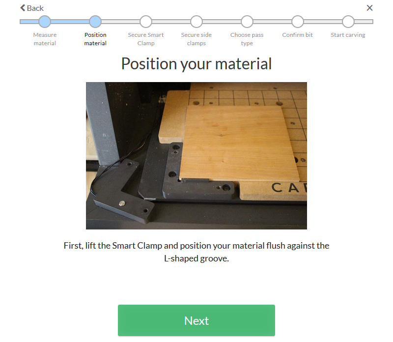
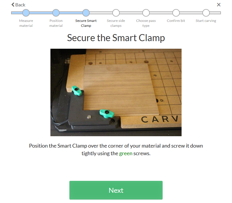
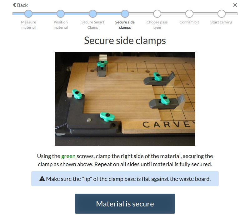
When ready to carve. Click on the Carve button and follow the steps as described below.
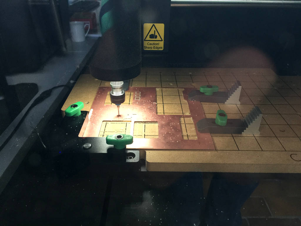
Milling the board.
Board milling.
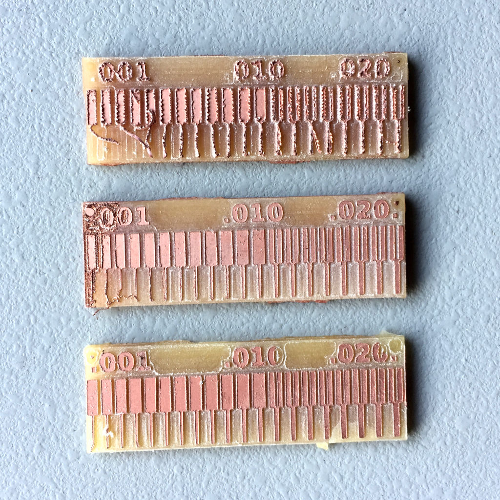
The final result.
Here are the milled traces. (top PCB) the milling with the V-shaped bit is too deep. It's an offset error from the Carvey. (Middle PCB) the PCB was not flat when milling. The clamps are not enough to make the PCB flat we should have used the double faced tape. (Bottom PCB) We have used the double faced tape and the clamp. This makes the PCB hard to remove but the results are much mcuh better. This is really important when we want a high milling resolution.