Group members: Axel Cornu, Nicolas De Coster, Victor Levy, Denis Terwagne
Week goal and files
For this assignment, we decided with our group to work on a calligraphy machine. For this, we will have to build a machine that moves in 2 horizontal axis and a vertical axis to control the brush up and down. We wanted to find the simplest and lightest type of machine for calligraphy for small dimensions of paper.
The goal of this week was to work as a team, to learn how to divide tasks, coordinate, keep a schedule ... What we set ourselves as a goal was to properly target the size and difficulty of what we were going to do so that what we wanted to achieve was possible with the team in the given time.
Machine Design
Team organization
For this week, we were aware that a "plan of attack" was needed. So we brought together the whole team of... two people : Victor and Nicolas (with our instructor, Denis, of course). Axel, who works with Denis, was also a big help to foreseen problems, propose a usable design (the 4xiDraw), and order the needed pieces (axis, ball bearings) etc. He was the 4th wheel our coach needed!
Building a machine from scratch with such a huge team didn't appear to be so easy, so we decided to split tasks based on favorite areas : Nicolas will be responsible for the more automation part while Victor will be in charge of the design part. That absolutely doesn't mean that each of us will work alone on his tasks...
We looked for some drawing and calligraphy machines to start from an existing base. A calligraphy machine is a 3-axis CNC with an end effector suitable for drawing with a brush, a fountain pen, a pencil ... It is a rather light machine whose components are not subjected to significant efforts. We eliminated the cable-based machines we tested at last year's fabacademy.
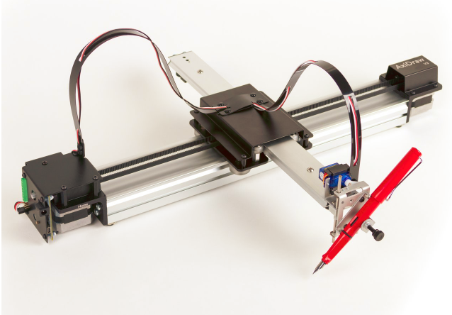
After some research and exchanges, Axel showed us the axidraw.This construction immediately seduced us by its simplicity and its compactness. In addition its construction seemed realistic to us with the size of our team.
Axel also helped us a lot so that things go smoothly by anticipating problems and ensuring the purchase of materials, electronics ... at the right time.
Team communication
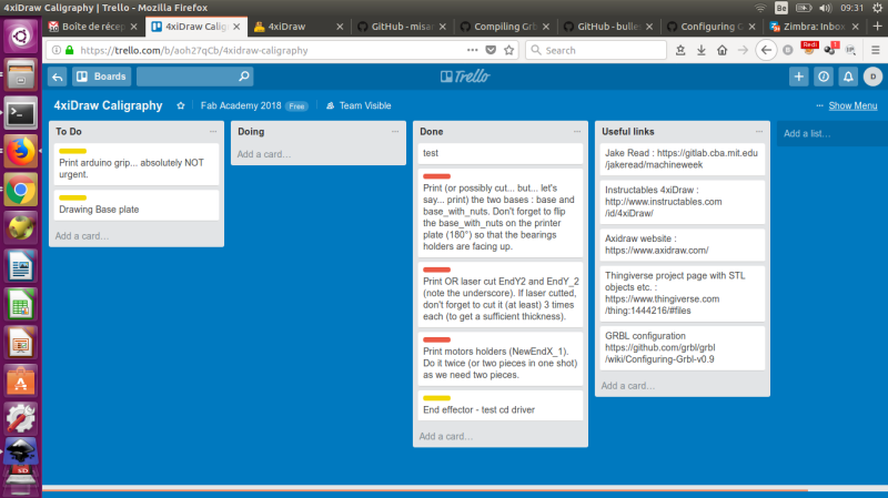
Victor and Nicolas have to manage a full-time job in their respective institutions (university and meteorological institute) in addition to the FabAcademy and it's not always possible to work in the same room on our stuffs so Denis proposed to create a trello to manage and split the different tasks so that "everyone" can keep an eye on the different parts being made. He thus created one.
We shared the tasks among us:Axel, Denis's assistant took care of the supplies and was there in support
Nicolas was in charge of the analysis of the machine, the electronic and the code.
Victor took care of the mechanical part, printing and construction.
Inspiration : 4xiDraw
We needed a quite simple design and we oriented ourselves to the 4xiDraw based on the AxiDraw design.
The thingiverse page of the 4xiDraw can ben found at https://www.thingiverse.com/thing:1444216/.
This is basically a 2+1 axes design. We mean : 2 classical XY directions and a servo motor +1 command to rise and lower the pen. This thus need to be controlled by a special flavor or the GRBL firmware to get a special output (1-2ms pulse) for the servo command as explained in the instructable. For more information about the stepper and servo motor commands, see Nicolas "ouput device" assignment where he tested both in prevision of this week.
Plan of attack and divison of labor
It was decided that :
- Nicolas first check the 4xiDraw design and try to understand exactly how it works.
- Based on his "analysis", he transmits to Victor the needed mechanical parts to be printed and he redesigns them if needed.
- Victor create the different elements and assemble them, making sure everything moves smoothly.
- We find together a solution for the brush vertical move.
- Nicolas automates all this with the needed electronic and software.
What has been most impressive in these two weeks is the fluidity of the work.
We had relatively little team work the four of us.
Much of the success of this experience was anticipation.
We chose to do a project on a realistic scale and this is probably one of the biggest lessons.
The division of tasks was clear, according to the best skills of each one, with a good timing.
This allowed us to work these two weeks in a fluid and efficient way.
Victor received from Nicolas a summary of the way the machine worked with the 6 pieces to print.
Victor did also some research and saw some videos on it.
We had at our disposal two 3D printers: the UP from TrioSlab and the Ultimaker 2+ from the Fablab ULB.
Time was running out and Victor had to finish the mechanical part of the machine for the Tuesday of the first week.
The plastic prints are on these two machines very slow.
So Victor opted for security by launching the most complicated parts (central) on both printers.
Victor's preference was for the UP also because it was easier to work with Axel next to us.
Printing the small parts was not a problem.
The central parts have been the subject of several tests and settings of the printer.
Victor used ABS and for the first impressions, the parts did not print well.
They bent and peeled off the hot plate.
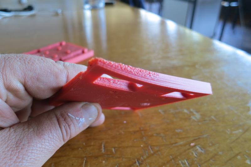
He changed the settings of 100 pc of filling to 75 pc.
The idea was to spread the effort in the structure of the material, which worked.
All the parts produced with this setting were perfect.
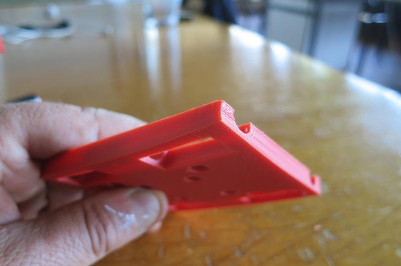
He also set a program setting that keeps the warming board running for 15 minutes after printing.
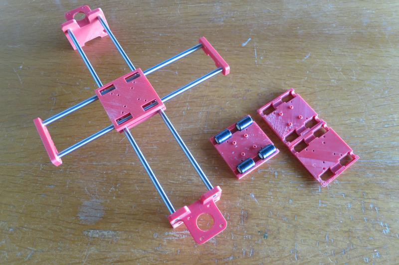
We also had a problem with the size of the bearings that slide on the rectified pins.
The dimensions of the pieces received did not correspond to the order.
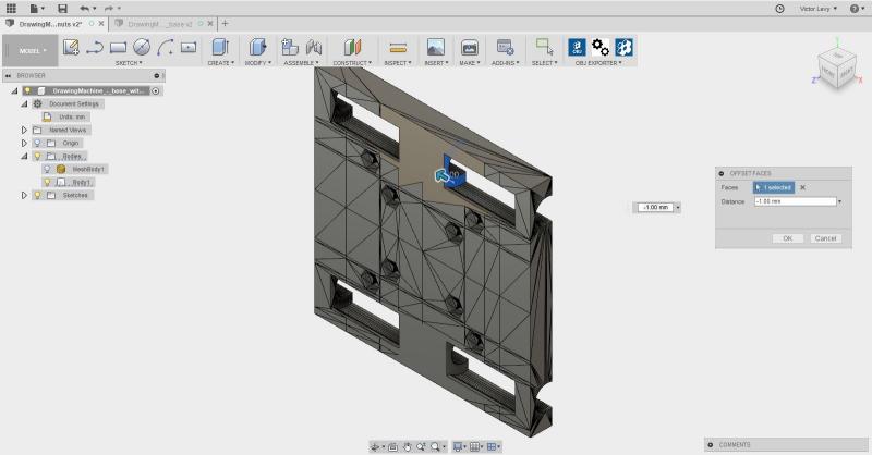
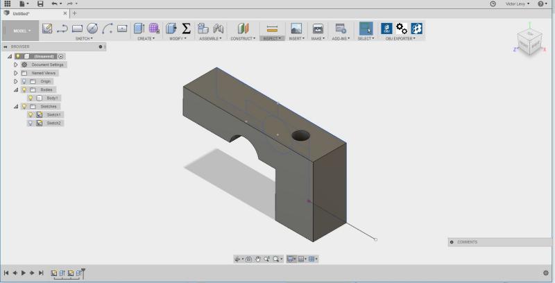
He had to modify the central parts on Fusion 360.
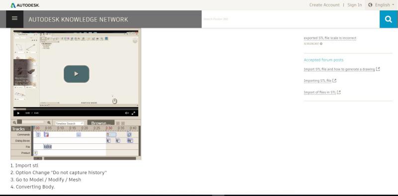
MODIFY THE STL
To do this we must go through a procedure a little complex and unnatural in four steps .
It is documented on the Autodesk website with a fairly clear video tutorial.
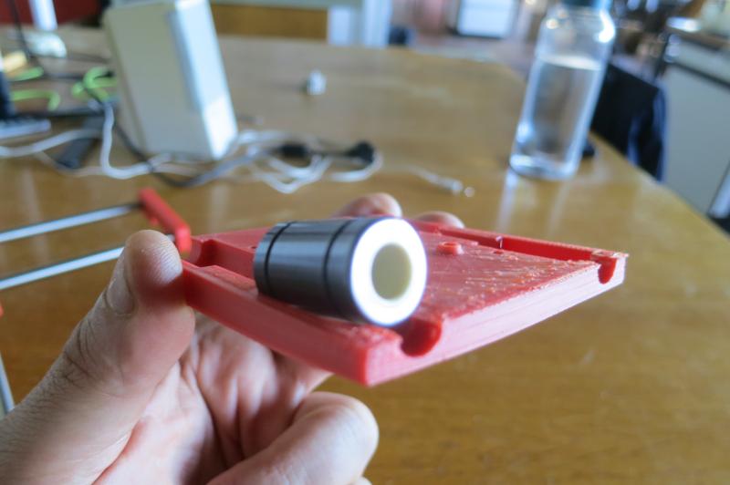
Victor added 1 mm to the hole to fit the bearings dimensions
unfortunately he did not pay attention to the diameter that was also wrong.
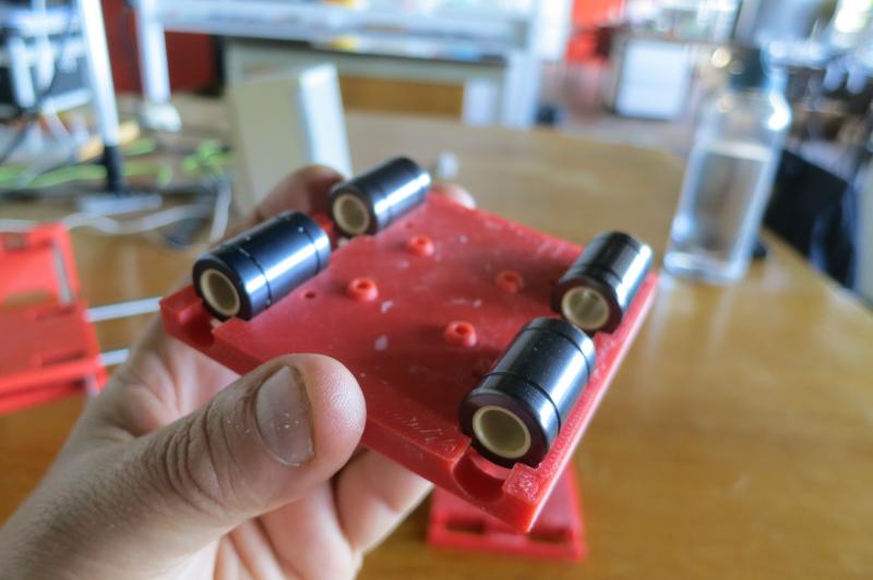
The two cylinders do not fit completely in the two central parts,
He had to add nuts to mount the four ball bearings that serve as a reference to the belt.
The placement of the belt was not simple ...
It had to be passed through the center in the right direction.
END EFFECTOR
We met again with Nicolas to work on the end effector.
He proposed Victor to hack a motor of a cd player.
This idea at first seemed a little silly and soon enough Victor agreed with his idea that proved very effective.
The motor of a cd player is a stepper motor and causes a piece to collide where the laser is.
Victor observed this piece and noticed that it was easy to fix it.
He removed the plastic parts that hold the axes, enlarged the holes and fixed it on the printed part of the Axidraw.
He used the Dremel with a 3mm wick after marking it.
To hold the brush, he drew a piece that pushed the brush on the moving part, using a bolt and a nut.
So much for Victor's part, it is Nico's work now...
Mechanical Design
After reading the all 4xiDraw documentation, Nicolas filled the trello with the information he found and sent an e-mail with all the needed files to Victor.
To summarize our choices : we knew that we had to go fast so cutting pieces (laser or CNC) in hard material (MDF, acrylic, ...) seemed a good choice as printing them is much slower than cutting them.
- But... looking closer at the motor holders, it looks that printing them would be much more reliable.
- For the central part it was less clear whether it was better to cut or print them : printing seemed one more reliable and the ball bearings looked better maintained in a curved slot. On the other hand, printing flat and rigid pieces is not that simple (as Victor's work proved later), and cutting them would be quicker. So Nicolas leaved this choice to Victor's discretion.
- The
Ytermination holder were not critical at all : so we can cut it but if Victor prefers to print them, it's okay too. No big deal. We just need to remember that theZaxis must be screwed on one termination.
Z-Axis
As said before, we didn't want to copy the pen mover from the 4xiDraw because it wasn't adapted to our japanese brush, so we needed to create something else. But we were in a rush, we couldn't find small axis and ball bearings etc. so... something came to Nico's mind : he dismounted two CD-ROM drivers during the "output device" assignment, after having played with a floppy driver. We didn't kept the electronic boards but the frame, motor and axis only. And it looks absolutely perfect for our purpose! Everything already mounted, moving smoothly, vertically... So we decided to screw it on the Y termination on our machine. It looks absolutely great and recycling by hacking is always big fun!
GRBL
GRBL is firmware that allows one to transform an arduino (or equivalent board) to a motors controller, converting the G-Code it gets through serial communication into corresponding pulses and directions, the same way as the floppy drive controller Nicolas tested during assignment 11 "outputdevices". For a complete list of supported G-Code, please refer to the GRBL documentation.
So the first thing Nicolas did was to read quickly the documentation available on the GRBL github. We strongly recommend that you do the same if you want to build a GRBL-based machine.
CNC shield and modules
The CNC shield is basically just a board that allow an easy inter-connection of the motors, the H-bridges motor controllers etc. Nothing very complicated but that's a very cheap and useful board.
So Nicolas first took it, looked at it carefully and try to figure out what pin is what so that he can understand how to use it properly.

For the information we could read and get from Axel (working in Denis Lab), here are the main thing to know about this CNC shield :
X.STEP/DIR...- Two pins providing the steps and the direction signals that will be used as information to move the motors
M0, M1, M2- Jumpers that allow to configure the microstepping configuration of the motors. (driver dependent) : the more microstepping you do, the most precise result you will get... but running slower. We decided to run on 1/8 stepping, wich is probably even too much as the precision is quite low with a calligraphy brush.
X, Y, Z 4-pins next to drivers- Are the output of the drivers : connexions for the motors, thus
X, Y, Z 4-pins under step/dir- Allows you to clone one of the three axis signals to the 4th driver (the red one on the picture)
Z+, Z-, ...- End Stop signals to avoid reaching the limit in movement and breaking thins
Others- Are quite self-explaining... aren't they?
For more information you can also read this manual (but we actually discovered it when documenting our work, not before, we didn't really looked for it because seemed quite clear).
First problem : making the Z-Axis move
First, we realized that the small stepper couldn't be controlled the same way as the two NEMA 17 motors because they are controlled with a 12V voltage and this little stepper has a coil resistance of 10Ω... which means 500mA under 5V if not current-controlled... wich already is 2.5W per coil (5W total). We DOUBT it could sustain a 12V controll and a small internet search confirmed our feelings... So let's be careful and make a first try independently.
Nicolas was super confident for this part because he created a super "stepper motor code generator" during "output device" week... so we just went to his page, configured the parameters quickly, load it to an arduino, connected a small H-bridge just like we did before, and... Nope. Dammit. Random behavior, going back and forth quickly, vibrating but not moving.
We checked the two coils : no interconnection, 10Ω each, 4 wires,... Thus checked the signals with the logical analyser : look exactly as we expected them... so...?
After searching a bit, checking everything, ... still nothing. So we did the same on the other unmounted CD-ROM driver : same strange behavior. We would have been very unlucky if both were broken so... time for an internet search. And we quickly found this. As we already knew the theory, we jumped to the code and... wait! That's not the signal we send! Searching a little bit more we discovered that they are 2-phases instead of 4-phases stepper motors! We didn't expect that.
So instead of copy/past the code... We went back to our "stepper motor code generator", added the corresponding sequence, re-generated the code... and it worked!
Ok now we know how to make our brush move vertically.
The first test of Z-axis going up and down. (controller by the microcontroller program, not the computer)
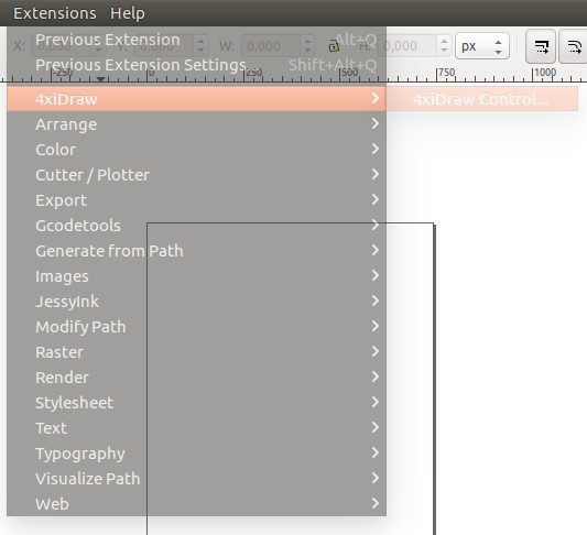
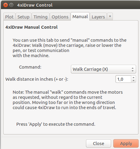
4xiDraw Inkscape module
On the instructable page, we read about the Torsten Martinsen's plugin for Inkscape that we thus download it on the github page.
To install the plugin, please refer to Nico's assignment week 03 "computer controlled cutting" as installing an add-on for Inkscape is already explained. Basically : just dowload/clone the files and extract the .inx and .py file in the right modules folder.
Second problem : missing library
But trying to launch the 4xiDraw module always bring us to an error when we try to launch it... So we tried to launch the Python module script in a python environment (because the error message in inkscape was nearly free of any information) and discovered that the inkex module couldn't be imported.
We very simply did :
locate inkex
/usr/share/inkscape/extensions/inkex.py
/usr/share/inkscape/extensions/inkex.pyc

cp /usr/share/inkscape/extensions/inkex.py* ~/.config/inkscape/extensions/
Here is the idea : the inkscape extension couldn't find the inkex library (probably a linking problem to the shared inkex library). But as we fount it (with the locate command) on the computer, we just copied the file (and its compiled version (.pyc)) into the local repository so that it can be found by the extension.
We are aware that there is a more clean solution... (as linking properly to the apparently already installed library instead of duplicating the files), but that one was efficient.
Third problem : serial communication unreachable
Now, with the arduino GRBL board connected, launching the 4xiDraw module provides me... nothing. A communication error telling us it can't find the board. How come?
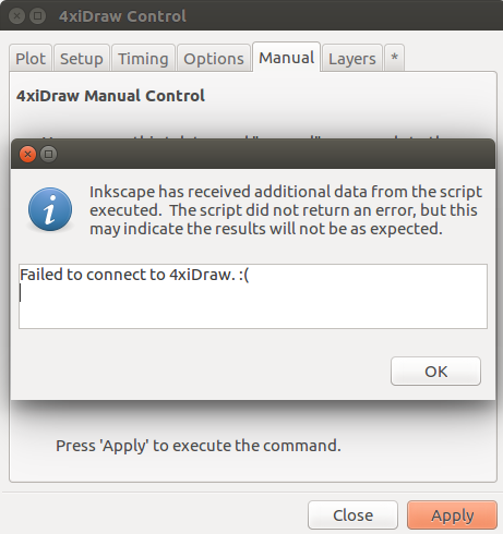
So, once more, we began to search for the right python script. We first tried a grep -R "ttyUSB" . and grep -R "ttyACM" . in the modules folder but without result. But then we realized that one file was called "grbl_serial.py" which sounds about like what I'm looking for... And thus executed it line by line with our attention on :
comPortsList = list(comports())
    for port in comPortsList:
        desc = port[1].lower()
        isUsbSerial = "usb" in desc and "serial" in desc
        isArduino = "arduino" in desc
        isCDC = "CDC" in desc
        if isUsbSerial or isArduino or isCDC:
            return port[0]
We just replaced the desc = port[1].lower() by print(port[1].lower()), which returned ttyacm0, that's why it couldn't be found by the next lines...
So we just modified the script slightly and quickly to make it able to find the ttyACM0. Not sure this is perfectly safe and clean (but not less than the original script?) but... it works!
comPortsList = list(comports())
for port in comPortsList:
    desc = port[1].lower()
    isUsbSerial = "usb" in desc and "serial" in desc
    isArduino = "arduino" in desc
    isCDC = "CDC" in desc
    isACM = "acm" in desc
    if isUsbSerial or isArduino or isCDC or isACM:
        return port[0]
#just to make it more clear
diff grbl_serial.py.bak grbl_serial.py
23c23,24
<             if isUsbSerial or isArduino or isCDC:
---
>             isACM = "acm" in desc
>             if isUsbSerial or isArduino or isCDC or isACM:
2-phases stepper "module"
As explained before, we couldn't control the CD-ROM stepper the same way as the two NEMA 17 motors, so we created quickly a small microprocessor code more or less based on Nico's stepper code generator. We didn't make it the "best" way but in a very quick, configurable and efficient way. Which basically means :
- By polling the "step" pin as an input
- When a low to high transition is detected : check the direction pin
- Depending on the direction pin, change the current "state" of the motor signal and send it
- Wait for the next step
We actually would have prefered to do it by interrupt-driven detection on pin change but that would need a bit more code to be really parametric. You'll see the first quick attempt with interrupt in our code, commented-out.
Instead of developing a physical board, we just loaded the code to an Arduino board and connected it to the Z dir/step signals on the CNC shield. Once more, not the best solution in our opinion but we don't have time to develop a real CNC-shield module to handle this.
Alternative stepper module
Another solution we considered was to re-use a floppy driver electronic board, as we tested it during assignment 11 "output devices" because it natively works with both direction and step signals and has the same type of motors... (but with shorter range).
But we prefered to do it ourselves for two reasons : make sure that we understand everything and for possible future development of a "real" module for the CNC shield.
Bringing it all together
Preliminary tests
Now that everything seems to be settled and working, time to connect it all together and launch a first test!
Orientation
We first checked the motor moves, so using the GRBL command line (via a serial terminal) we tested the X and Y moves.
The X move was actually obtained by launching a X100 Y100 command (making both motors turning in the same direction), because of the H-Bot configuration as explained on instructable
The Y move was actually obtained by launching a X40 Y-40 command (making the motors turning in opposite direction), because of the H-Bot configuration as explained on instructable
Square and circle
As a very first test, we draw a simple square, but there is no "Z-control" so far, so the brush will stay low.
As a second test, we draw a circle, the brush is still not controlled.
Controlling the Z axis with GRBL
To make sure the module works properly with the GRBL board, we first checked the signal send by the GRBL board and the connected the module to the board.


Steps are on the yellow channel, Direction is provided on the green channel.Now, the Z axis is well controlled by the GRBL board, but still moving too fast.
Adjusting the parameters
We then quickly adjusted the different parameters on the GRBL board (see GRBL documentation) and configured them so:
$$

$0=10
$1=25
$2=0
$3=0
$4=0
$5=0
$6=0
$10=1
$11=0.010
$12=0.002
$13=0
$20=0
$21=1
$22=0
$23=0
$24=25.000
$25=500.000
$26=250
$27=1.000
$30=1000
$31=0
$32=0
$100=40.000
$101=40.000
$102=5.000
$110=1000.000
$111=1000.000
$112=1000.000
$120=100.000
$121=100.000
$122=10.000
$130=200.000
$131=200.000
$132=200.000
What each parameters means and how it should be configured is detailed here
Real first print
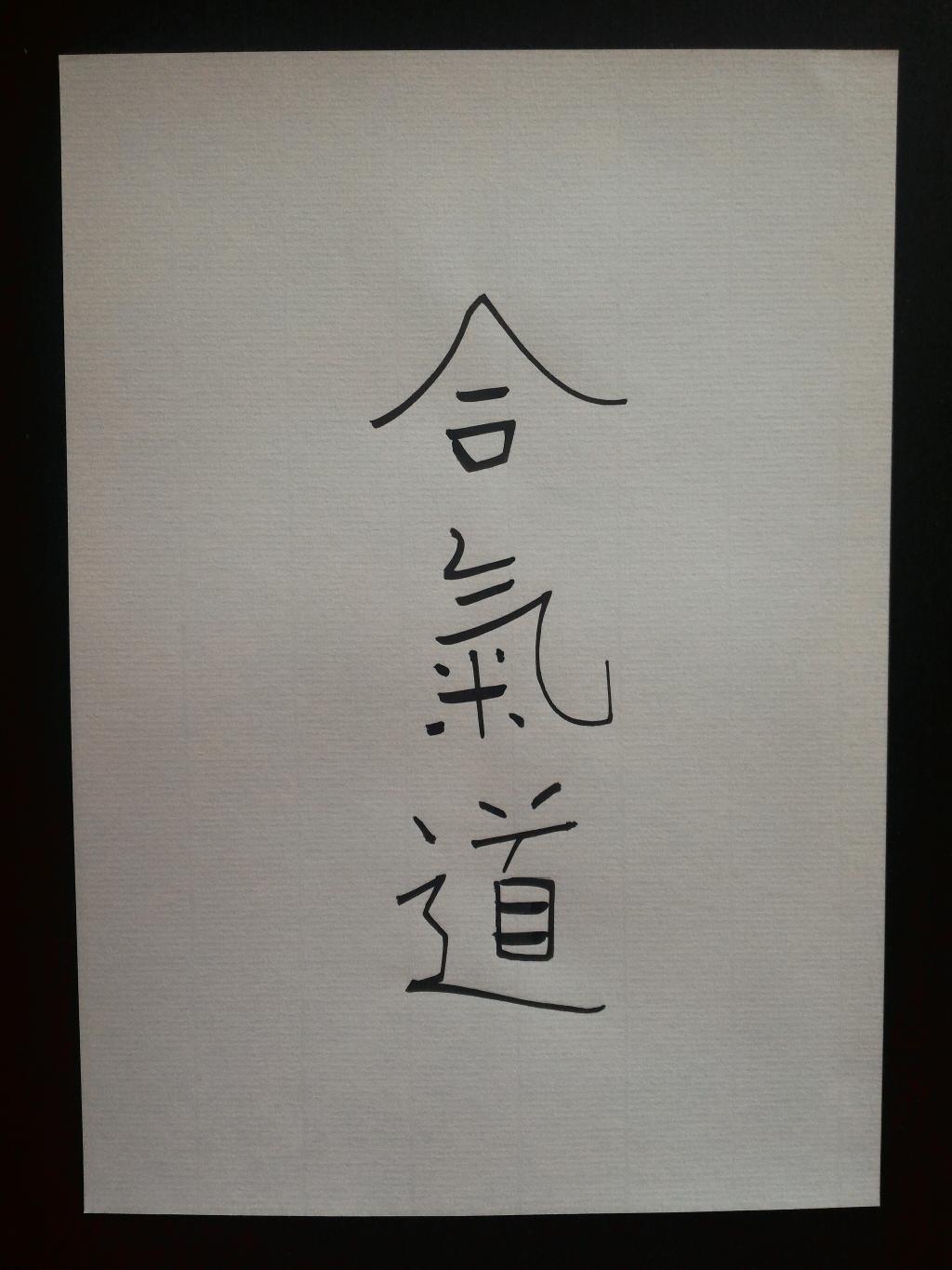
As we are working on Japanese calligraphy, the first thing that came to Nico's mind was the "AiKiDo" pictogram, as he practiced for some years (currently in pause for different reasons but still determined to go back soon). So he checked the pictogram (no chance he can draw it without checking).
Because the brush suppleness will provide part of the move, we just draw the lines "manually" on inkscape, keeping most of them straight and several very simple curves.

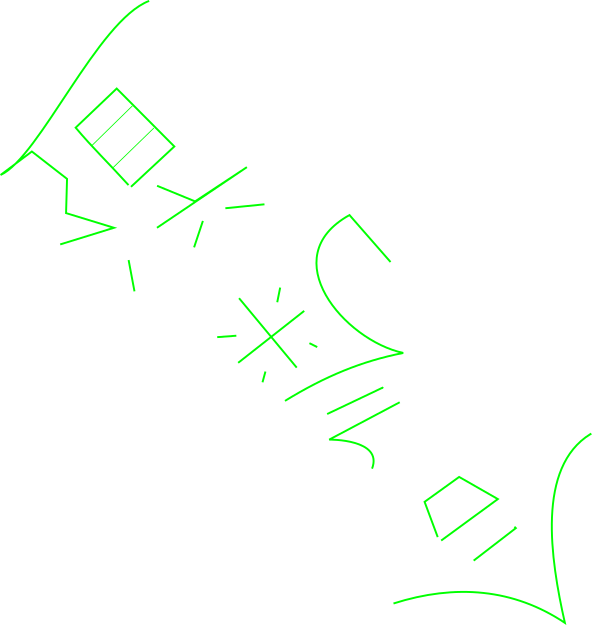
The very first words of our incredible machine! (but speaking "in mirror"... we realized that later)
Readjusting parameters
Adjusting Z moves
We then adjusted a little bit better the Z moves so that the brush comes gently on the paper : just touching but not too low to obtain thinner traces.
To do so, I played a bit with the value into the file grbl_motion.py
  def sendPenUp(self, PenDelay):
    if (self.port is not None):
      strOutput = 'G1 F10000 Z-11\r'       # -16 is the the Z value when the pen is Up
      self.port.command(strOutput)
      strOutput = 'G4 P' + str(PenDelay/1000.0) + '\r'
      self.port.command(strOutput)

  def sendPenDown(self, PenDelay):
    if (self.port is not None):
      strOutput = 'G1 F10000 Z-16\r'       # -16 is the the Z value when the pen is Down
      self.port.command(strOutput)
      strOutput = 'G4 P' + str(PenDelay/1000.0) + '\r'
      self.port.command(strOutput)
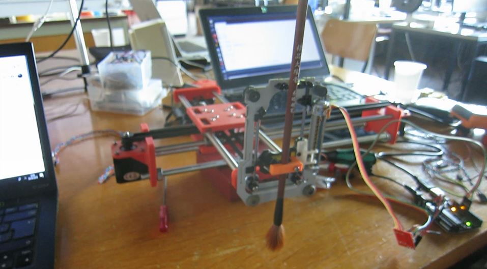
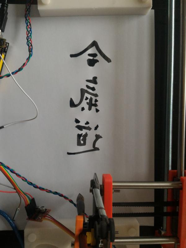
Final result
"Oh... And one more last thing."
Ok, we actually mean : many more last things
About team organization
Despite we created a "trello" to organize our work, it wasn't really helpful and used it just to keep documentation up-to-date. As we were actually two... it was much easier to catch the phone or to meet.
Things that still need to be done
Direction / moves
The H-Bot architecture doesn't use separated X and Y directions as explained before. So we should adapt the motor commands to that architecture to avoid 45° transform.
Stop end detectors
Currently our design is only "aware" of its own "printing area". But we should also place a more hardware control to avoid collision. The other current problem is that as long as the direction/moves problem isn't fixed, dimensions are not correctly interpreted because of the 45° angle.
Auto-zeroing
Once the stop detector placed, it would also be possible to do an auto "zeroing" using them.