Electronic architectures
We tested quite quickly several other electronic architectures.
We tried to do a "loop" and "toggle" test for each architecture. The blank section are tests that we still intend to do.
As Nicolas already knew some stuffs about Microchip, he showed us how to use it after coming back from Paris.
PIC (Microchip)
We actually learned digital electronics and assembly code on microchip's architecture, several years ago. Since then I've created tens of circuits based on those microchip microcontrollers, from a decorative pumpkin for Halloween (my very first circuit), a copy of my car remote key, various domotic controllers, etc.
We won't develop here every details but, as an example, we wanted to show quickly how to do with Microchip architecture.
MPLAB IDE
The most recent tool to develop with Microchip architecture is "Mplab X IDE". As it was developped in Java, it's available for the three classical OS (Linux, Mac and Windows). Everything is well documented so we won't develop installation's procedure. Just be aware that you also need to download a compiler adapted to the architecture you want to code (8bits, 16 bits or 32 bits). But once again, this is explained at the end of the MPLAB environment installation.
The Programmer (PicKit 3 and others)
My very first programmer was homemade as it is possible to program most of the Microchip microcontroller with a slightly transformed UART converter. (I actually even used a "real" RS-232 port). The only "tricky" point was to have 12V on the reset pin required to program the chip.
Now we use a PicKit 3 programmer. It's not expensive (~30$) and quite useful : it can program your chips, has protections, and can debug the chips that don't require debug headers. We would recommend it, even though making your own programmer is always a good lesson!
Create a project
To create a new project, just click New > Project (what a surprise), and then select your part, the desired compiler and project location. We would also recommend to use the utf-8 format for your files, especially if you often switch between different OS.
If you want your programmer to provide the necessary voltage to your board, go to file > project properties > pickit3 > power > power target circuit from pickit3
Writing code
First, you must know the MCC (Microchip Code Configurator) that can be very helpfull to set the different fuses (there are many, depending on your chip). So if it's not done yet, go to Tools > Plugin Download and add the MCC.
Then right click on the source code folder in your project and add a new C file, OR use the MCC to create a new project.
Because we're lacking time (yes, once more), we'll just put the file we wrote (volunteerly in one single file to make it simpler) with comments.
Quick note : as in AVR, you have to use two different to read an write the ports. In Microchip the port (PORTx) is used to read and the latch (LATx) register is used to write. (It can be a bit confusing as in AVR PORTx is used to write and PINx to read). You can manipulate bits directly.(Rxn and LATxn).
#include <xc.h>
// Configuration bits: selected in the GUI
// CONFIG1H
#pragma config FOSC = INTIO67 // Oscillator Selection bits->Internal oscillator block, port function on RA6 and RA7
#pragma config FCMEN = OFF // Fail-Safe Clock Monitor Enable bit->Fail-Safe Clock Monitor disabled
#pragma config IESO = OFF // Internal/External Oscillator Switchover bit->Oscillator Switchover mode disabled
// CONFIG2L
#pragma config PWRT = OFF // Power-up Timer Enable bit->PWRT disabled
#pragma config BOREN = SBORDIS // Brown-out Reset Enable bits->Brown-out Reset enabled in hardware only (SBOREN is disabled)
#pragma config BORV = 18 // Brown Out Reset Voltage bits->VBOR set to 1.8 V nominal
// CONFIG2H
#pragma config WDTEN = OFF // Watchdog Timer Enable bit->WDT is controlled by SWDTEN bit of the WDTCON register
#pragma config WDTPS = 32768 // Watchdog Timer Postscale Select bits->1:32768
// CONFIG3H
#pragma config CCP2MX = PORTC // CCP2 MUX bit->CCP2 input/output is multiplexed with RC1
#pragma config PBADEN = ON // PORTB A/D Enable bit->PORTB<4:0> pins are configured as analog input channels on Reset
#pragma config LPT1OSC = OFF // Low-Power Timer1 Oscillator Enable bit->Timer1 configured for higher power operation
#pragma config HFOFST = ON // HFINTOSC Fast Start-up->HFINTOSC starts clocking the CPU without waiting for the oscillator to stablize.
#pragma config MCLRE = ON // MCLR Pin Enable bit->MCLR pin enabled; RE3 input pin disabled
// CONFIG4L
#pragma config STVREN = ON // Stack Full/Underflow Reset Enable bit->Stack full/underflow will cause Reset
#pragma config LVP = ON // Single-Supply ICSP Enable bit->Single-Supply ICSP enabled
#pragma config XINST = OFF // Extended Instruction Set Enable bit->Instruction set extension and Indexed Addressing mode disabled (Legacy mode)
#pragma config DEBUG = OFF // Background Debugger Enable bit->Background debugger disabled, RB6 and RB7 configured as general purpose I/O pins
// CONFIG5L
#pragma config CP0 = OFF // Code Protection Block 0->Block 0 (000800-001FFFh) not code-protected
#pragma config CP1 = OFF // Code Protection Block 1->Block 1 (002000-003FFFh) not code-protected
#pragma config CP2 = OFF // Code Protection Block 2->Block 2 (004000-005FFFh) not code-protected
#pragma config CP3 = OFF // Code Protection Block 3->Block 3 (006000-007FFFh) not code-protected
// CONFIG5H
#pragma config CPB = OFF // Boot Block Code Protection bit->Boot block (000000-0007FFh) not code-protected
#pragma config CPD = OFF // Data EEPROM Code Protection bit->Data EEPROM not code-protected
// CONFIG6L
#pragma config WRT0 = OFF // Write Protection Block 0->Block 0 (000800-001FFFh) not write-protected
#pragma config WRT1 = OFF // Write Protection Block 1->Block 1 (002000-003FFFh) not write-protected
#pragma config WRT2 = OFF // Write Protection Block 2->Block 2 (004000-005FFFh) not write-protected
#pragma config WRT3 = OFF // Write Protection Block 3->Block 3 (006000-007FFFh) not write-protected
// CONFIG6H
#pragma config WRTC = OFF // Configuration Register Write Protection bit->Configuration registers (300000-3000FFh) not write-protected
#pragma config WRTB = OFF // Boot Block Write Protection bit->Boot Block (000000-0007FFh) not write-protected
#pragma config WRTD = OFF // Data EEPROM Write Protection bit->Data EEPROM not write-protected
// CONFIG7L
#pragma config EBTR0 = OFF // Table Read Protection Block 0->Block 0 (000800-001FFFh) not protected from table reads executed in other blocks
#pragma config EBTR1 = OFF // Table Read Protection Block 1->Block 1 (002000-003FFFh) not protected from table reads executed in other blocks
#pragma config EBTR2 = OFF // Table Read Protection Block 2->Block 2 (004000-005FFFh) not protected from table reads executed in other blocks
#pragma config EBTR3 = OFF // Table Read Protection Block 3->Block 3 (006000-007FFFh) not protected from table reads executed in other blocks
// CONFIG7H
#pragma config EBTRB = OFF // Boot Block Table Read Protection bit->Boot Block (000000-0007FFh) not protected from table reads executed in other blocks
#define _XTAL_FREQ 64000000
/*
Main application
*/
void main(void)
{
// SCS FOSC; OSTS intosc; IRCF 16MHz_HFINTOSC; IDLEN disabled;
OSCCON = 0x70;
// INTSRC disabled; PLLEN enabled; TUN 0;
OSCTUNE = 0x40;
//put all values to zero
LATA = 0;
LATB = 0;
LATC = 0;
LATD = 0;
LATE = 0;
/**
TRISx registers
*/
//Make everyone output (to minimize consumption and avoid floating inputs)
//except RC6 that is an input
TRISA = 0;
TRISB = 0;
TRISC = 0 | (1 << 6); //RC6 is input (1), all the others are output (0)
TRISD = 0;
TRISE = 0;
/**
ANSELx registers
Make sure that the analog inputs/module are deactivated
*/
ANSELH = 0x1F;
ANSEL = 0xFF;
/**
WPUx registers
*/
WPUB = 0xFF;
INTCON2bits.nRBPU = 0;
LATD = 0 | (1 << 0);
while (1)
{
/////////////
// Simple test : set output = not(input) unique line : 1.455MHz = 11 ICy
// in case of repeated explicit instructions : 1.231 MHz = 13 ICy
/////////////
// LATC5 = ~RC6;
// LATC5 = ~RC6;
// LATC5 = ~RC6;
// LATC5 = ~RC6;
// LATC5 = ~RC6;
// LATC5 = ~RC6;
// LATC5 = ~RC6;
// LATC5 = ~RC6;é
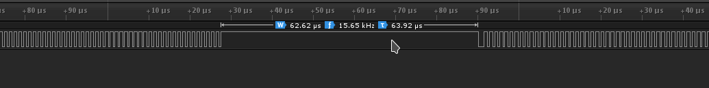
////////////
// Pure assembly test
////////////
#asm
MainLoop:
BTFSC PORTC, 6
BRA IfSet
BSF LATC, 5
BRA MainLoop
IfSet:
BCF LATC, 5
BRA MainLoop
#endasm
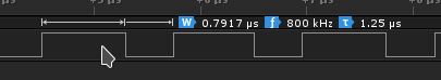
/////////////
// Toggling: 2.666 MHz = 6 ICy
/////////////
// LATC5 ^= 1;
/////////////
// Explicit repeat toggling: 8MHz = 2 ICy
/////////////
// LATC5 ^= 1;
// LATC5 ^= 1;
// LATC5 ^= 1;
// LATC5 ^= 1;
// LATC5 ^= 1;
// LATC5 ^= 1;
// LATC5 ^= 1;
}
}
/**
End of File
*/
MSP (Texas Instruments)
Despite we have a test module for the MSP430G2, I'm really lacking time to test and document it. we hope to do it a little bit later.
Banana Pi M2U (single board computer)
The Banana Pi M2U is just another single board computer. They become very famous and are often confused with "super microcontrollers", which they are not.
The Banana Pi M2U is very similar to the most known Raspberry Pi 3 but also includes : a Sata port, a real time clock, an on-board 8GB flash memory, and several other features.
To work with the Banana Pi, we decided to use the serial terminal instead of connecting a screen, keyboard etc. To do so, we just connected a FTDI converter (jumper configured in 3.3V! 5V could be damagable). If the serial terminal is not available, just connect your Pi to a screen and keyboard and use the raspi-config command to set it. (even on the Banana...). Be careful : as we already said it, there often is a confusion about how to connect pins in serial communication. Connect your FTDI's Tx pin to the Rx pin of the Pi and, reciprocally, the Rx to Tx.
We then created the same example codes that for the microcontrollers (software toggles and read-write-loops).
Preparing the Pi
Wifi network.
As it was easier for me to work with the wifi (and my smartphone to make it mobile anywhere in Paris ;-) ) we first configured the wifi network following those very simple steps.. Actually if the network is strong enough (i.e. the smartphone close enough to the Pi), you don't even require the wifi antenna to be connected.
WiringPi (controlling GPIOs)
There are different ways to controll the GPIO on a Pi board. One of them is using the WiringPi library (I personally used the BPI implementation, see below).
git clone https://github.com/BPI-SINOVOIP/BPI-WiringPi2.git
cd BPI*
chmod +x ./build
sudo ./build
Connecting
I used the available schematics on the net and the gpio readall command to know which pin is what.

gpio readall

 +-----+-----+---------+------+---+---Pi ?---+---+------+---------+-----+-----+
 | BCM | wPi |   Name  | Mode | V | Physical | V | Mode | Name    | wPi | BCM |
 +-----+-----+---------+------+---+----++----+---+------+---------+-----+-----+
 |     |     |    3.3v |      |   |  1 || 2  |   |      | 5v      |     |     |
 |  53 |   8 |   SDA.1 | ALT5 | 0 |  3 || 4  |   |      | 5v      |     |     |
 |  52 |   9 |   SCL.1 | ALT5 | 0 |  5 || 6  |   |      | 0v      |     |     |
 |  35 |   7 | GPIO. 7 | ALT3 | 0 |  7 || 8  | 0 | ALT4 | TxD     | 15  | 274 |
 |     |     |      0v |      |   |  9 || 10 | 0 | ALT4 | RxD     | 16  | 275 |
 | 276 |   0 | GPIO. 0 | ALT3 | 0 | 11 || 12 | 0 | ALT3 | GPIO. 1 | 1   | 273 |
 | 277 |   2 | GPIO. 2 | ALT3 | 0 | 13 || 14 |   |      | 0v      |     |     |
 | 249 |   3 | GPIO. 3 | ALT2 | 0 | 15 || 16 | 0 | ALT3 | GPIO. 4 | 4   | 272 |
 |     |     |    3.3v |      |   | 17 || 18 | 0 | ALT2 | GPIO. 5 | 5   | 250 |
 |  64 |  12 |    MOSI | ALT4 | 0 | 19 || 20 |   |      | 0v      |     |     |
 |  65 |  13 |    MISO | ALT4 | 0 | 21 || 22 | 0 | ALT2 | GPIO. 6 | 6   | 251 |
 |  66 |  14 |    SCLK | ALT4 | 0 | 23 || 24 | 0 | ALT4 | CE0     | 10  | 87  |
 |     |     |      0v |      |   | 25 || 26 | 0 | ALT2 | CE1     | 11  | 248 |
 | 257 |  30 |   SDA.0 | ALT3 | 0 | 27 || 28 | 0 | ALT3 | SCL.0   | 31  | 256 |
 | 224 |  21 | GPIO.21 | ALT4 | 0 | 29 || 30 |   |      | 0v      |     |     |
 | 225 |  22 | GPIO.22 | ALT4 | 0 | 31 || 32 | 0 | ALT3 | GPIO.26 | 26  | 116 |
 | 226 |  23 | GPIO.23 | ALT4 | 0 | 33 || 34 |   |      | 0v      |     |     |
 | 227 |  24 | GPIO.24 | ALT4 | 0 | 35 || 36 | 0 | ALT4 | GPIO.27 | 27  | 231 |
 | 228 |  25 | GPIO.25 | ALT4 | 0 | 37 || 38 | 0 | ALT4 | GPIO.28 | 28  | 230 |
 |     |     |      0v |      |   | 39 || 40 | 0 | ALT4 | GPIO.29 | 29  | 229 |
 +-----+-----+---------+------+---+----++----+---+------+---------+-----+-----+
 | BCM | wPi |   Name  | Mode | V | Physical | V | Mode | Name    | wPi | BCM |
 +-----+-----+---------+------+---+---Pi ?---+---+------+---------+-----+-----+
But testing the pins before starting (to make sure we don't make mistake in my connections) provided me some strange results. we couldn't get the 5V on the 5V pins (I measure 0V) while all the other pins seem correct. I'll investigate it later.
Because all the reste looked correct, we thus made a first test using the example code "blink.c" (my module being connected to the wPi 0 pin = physical 11 = BCM 276).
gcc -Wall -o blink blink.c -lwiringPi
sudo ./blink
Bash implementation
As the gpio readall provided me the BCM numbering of the pins we used the wPi 0 (=BCM 276) as output pin and the wPi 2 (=BCM 277) as input pin, connected together. Here is my code in Bash:
#!/bin/sh

#echo "276" > /sys/class/gpio/export
#echo "out" > /sys/class/gpio/gpio276/direction
#echo "277" > /sys/class/gpio/export
#echo "in" > /sys/class/gpio/gpio277/direction

while true
do
    if [ $(cat /sys/class/gpio/gpio277/value) = 1 ]
    then
        echo 0 > /sys/class/gpio/gpio276/value
    else
        echo 1 > /sys/class/gpio/gpio276/value
    fi
done
Python implementation
We also tried to do it in Python but we got some troubles with pin numbering or the BPI.
sudo python
>>> import BPI.GPIO as GPIO
>>> GPIO.setmode(GPIO.BCM)
>>> GPIO.setup(276, GPIO.OUT)

Traceback (most recent call last):
  File "<stdin>", line 1, in <module>
ValueError: The channel sent is invalid on a Raspberry Pi
It looks like the problem comes from the porting of Raspberry's library to the BananaPi. Once again : no time to investigate much more...
C implementation
Note that the pins a now referred with their wPi numbers
#include <stdio.h>
#include <errno.h>
#include <stdlib.h>
#include <wiringPi.h>

#define OUT_PIN 0
#define IN_PIN  2

/*
 *********************************************************************************
 * main
 *********************************************************************************
 */

int main (void)
{
  wiringPiSetup () ;

  pinMode (OUT_PIN, OUTPUT) ;
  pinMode (IN_PIN, INPUT) ;

  while(1){
    if(digitalRead(IN_PIN)){digitalWrite(OUT_PIN, LOW);}
    else                   {digitalWrite(OUT_PIN, HIGH);}
  }
  return 0 ;
}