3d scanning & printing
Feb 21 - feb 28
● The goal for this week was to design a 3D model which can not be created by subtractive manufacturing, also print the same model using a 3D Printer. I have been designing and printing different kinds of models from quite sometime now as a profession, also conducting several types of workshops and demonstrations for the same. I feel this week was quite comfortable compared to other weeks, but I still looked forward to learn more.
● My assignment also included scanning a model using the Sense Scanner available at our lab. Learning the techniques for scanning different objects.
● Group assignment for the week was to group assignment: - test the design rules for your 3D printers, to identify the tolerance of 3D Printers by printing a tolerance test for future accurate printing.
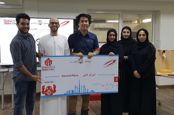
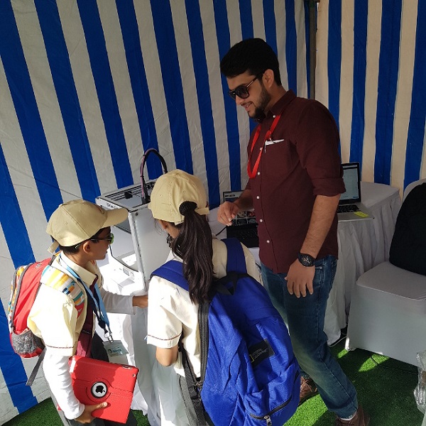
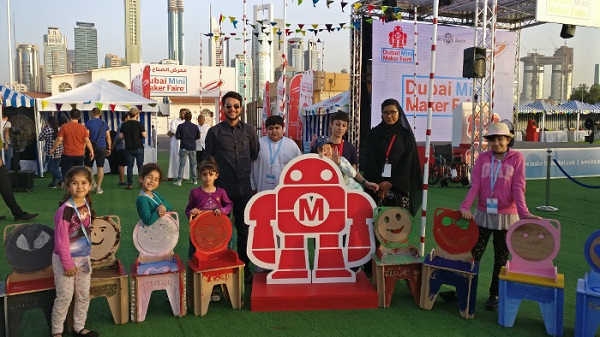
● The best part of this week was that we attended the Dubai Mini Maker Faire by the FABLAB UAE for four days, which was very exciting in terms of getting to know a lot of new stuff happening in the industry, also we set-up a stall for 3D Printing to showcase the technology to a large group of school students attending the faire and other professionals. We had a great time and connected to a lot more like minded and equally passionate individuals.
● It's been the most INTENSE WEEK because we, the Fab Academy students form FABLAB UAE also registered ourselves and took part in the HACKATHON competition sponsored by the Hamdan Award group. And our challenge to overcome was to convert an idea into a reality in 4 days. The idea assigned to our group was to create a battery powered waterproof bracelet with an emergency button which sends across the location coordinates via an app through wifi.
● Our team won the 2nd prize and received AED 10,000 as a reward for the hard work, dedication and effort put in to make the super smart Saviour Bracelet.
getting started
● Visit Our Group Page to check out the range of tests we carried out during this week to test different materials, process parameters and 3D Printers. Which helped us identify the correct settings to be used in this week's assignment.● Same as the previous weeks, I had nothing in mind and did not know where to start, the idea was to create something and 3D Print, which can not be achieved by subtractive manufacturing technique.
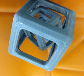
● So, I decided to make a cube in cube in cube design, I wished to keep things minimal and because honestly we did not have much time this week, we were attending the Maker faire and also participating in the Hackathon competition, both of which were amazing opportunities.
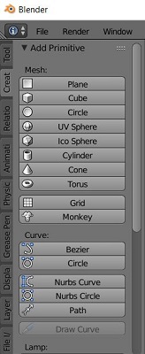
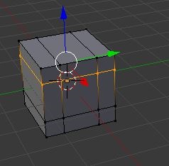
● The below image shows the create option in blender and this is where I select my cube to start with. The design is such that it can not be created by using a subtractive manufacturing technique, because there is a cube in feature of the product which can only be created using layer by layer fabrication, it has been designed such that the cube inside one another would not fall out of each other. Therefore, this design is only possible by additive manufacturing / 3D Printing.
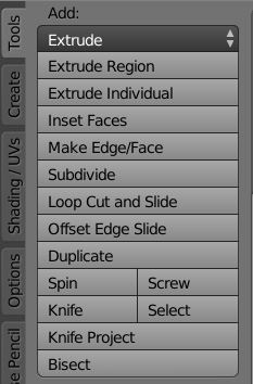
● Then moving on, I selected the Loop cut and slide option to cut the cube in the way I have shown in the below image. This particular tool lets a user slide and cut through any object or body and also in any axis. The following cuts are performed in all x,y,and z axis because I wanted the cube to be symmetrical.
The important shortcuts for Blender are:
● S - Scale objects
● E - Extrude
● R - Rotate
● X - Delete
● Q - Change views
● A - Select / Deselect All
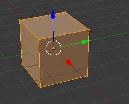
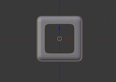
● I deleted the faces except the ones you see in the picture below. The idea was to limit my model to just a few cm.
● The next step was to duplicate the model of the cube which was designed and reducing the scale so that the smaller cube fits in the original one.
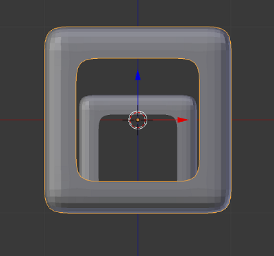
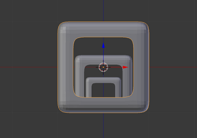
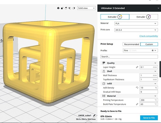
● Following the same step again to duplicate the smaller cube to form one more smaller cube in scale to fit in the latter. I finalized this model and gave it the dimensions of 50x50x50 for a faster print. I save exported the file in the form of .stl in order to be recognized by the slicing software, in this case was CURA for Ultimaker 3 Extended.
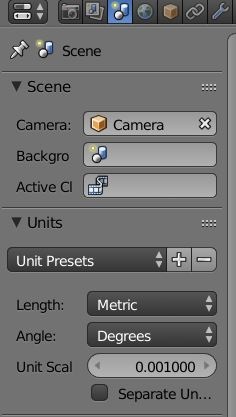
● In the scene option on the right side of the software, I selected the units as metrics and the value as 0.001 in order for the software to present the model in mm.
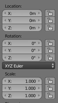
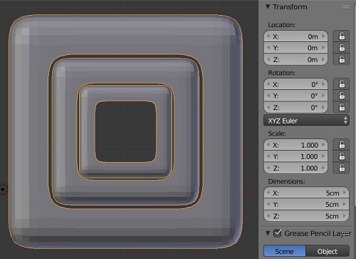
● The following image shows the window where a user can define a location, rotation and scale for their particular model, in my case all of the parameters were selected as per the image.
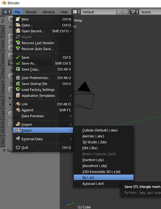
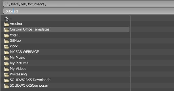
● In order to save the file, we choose file/export/.stl so that we can 3D print the design.
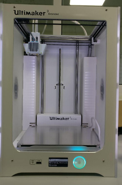
● We had the amazing Ultimaker 3 Extended at the lab to work on, which is quite a phenomenal machine in terms of accuracy, precision and print time.
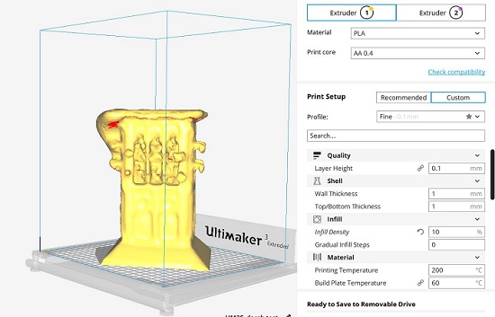
● I got the model into cura for slicing the same into layers, the process parameters selected by me are also shown in the picture below. Once the slicing is done with, I then saved the gcode file on a flash drive which can used to print on the 3D Printer.
● Based on our tests carried out for the group assignment I had a clear idea of selecting the process parameters accordingly.
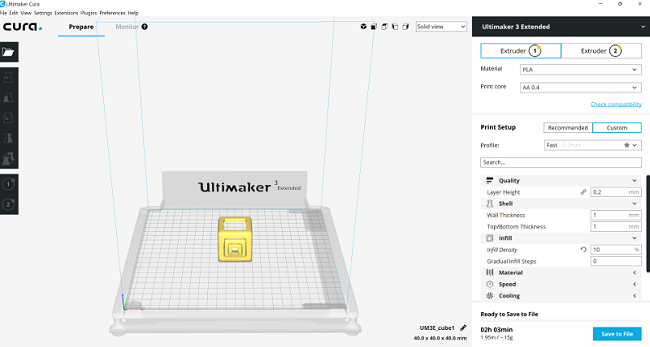
● We used PLA (polylactic acid) the biodegradable thermoplastic material to print the 3d model and the process parameters for the same were as follows:
● Layer Height: 0.2 mm
● Shell Thickness: 1mm
● Infill density: 10%
● Print core: 0.4 mm
● Material: Single(PLA)
● Printing Temp: 200 C
● Build Plate Temp: 60 C
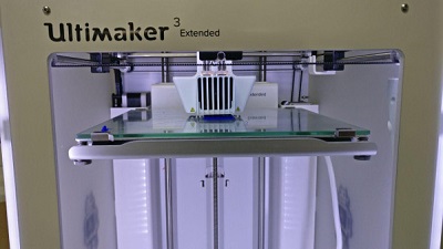
● You can witness the machine printing the cube in blue color, which took about an hour for the print.
The issue
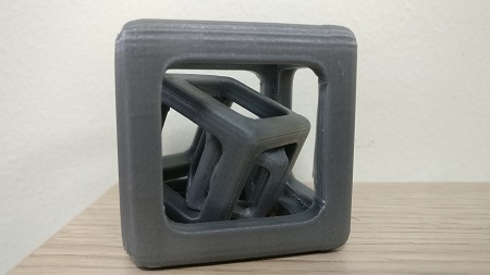
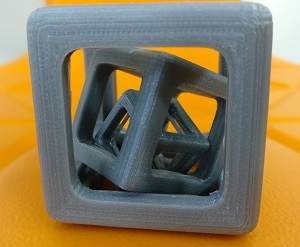
● I faced an issue, which was not a major one, but I did a minor error by selecting the raft as bed adhesion, in this particular case I did not a raft and actually because of the raft all the three cubes were stuck to each other as shown in the picture below.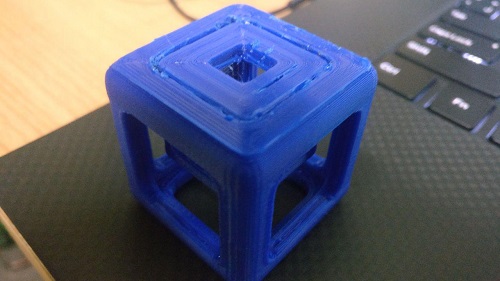
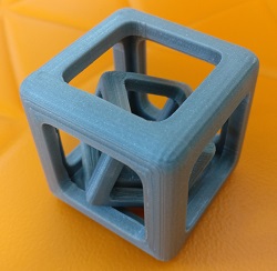
● Then I decided to print the model again, without any bed adhesion. To achieve the cube as per the requirement of free movement inside one another.
● I also increased a the size of the cube to 50x50x50 mm and printed with the same settings except adding any sort of bed adhesion.
An unintenional error is that, the cubes do fall out down from inside one another, so next time I shall make sure to check all views in my model and avoid the same. To avoid the error I could fine tune the parameter for support in Cura or also I could make the support structure in blender itself to achieve the cubes as per requirement and then export it.
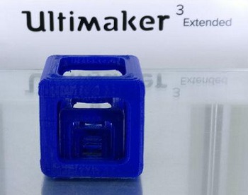
Here, we have the final 3d print model.
3d scanning
● 3D scanning is something I have practiced in past along with 3D printing. The scanners that I have used in past are the David Scanner, Scan in a Box and Sense scanner.● The 3D scanning technologies rely on different physical principles and can be classified in categories:
● Laser triangulation 3D scanning technology, as illustrated on the image, projects a laser beam on a surface and measures the deformation of the laser ray.
● Structured light 3D scanning technology measures the deformation of a light pattern on a surface to 3D scan the shape of the surface.
● Photogrammetry, also called 3D scan from photographies, reconstructs in 3D a subject from 2D captures with computer vision and computational geometry algorithms.
● Contact based 3D scanning technology relies on the sampling of several points on a surface, measured by the deformation of a probe.
● Chect out HERE for more info on the scaning processes and technologies as explained above.
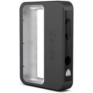
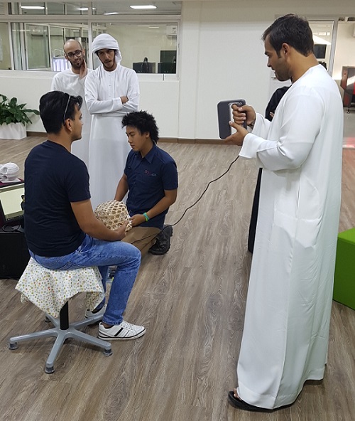
● I selected to scan a Fake Plant which was present in the lab and we used the Sense scanner by 3D Systems, one of the major companies in the industry.
● The Sense 3D scanner is light, highly portable and small enough to fit in your laptop bag so you can scan data wherever you are and bring it back to the office to complete and enhance your designs.
● Follow the LINK for more info on 3D Scanning using the Sense Scanner.
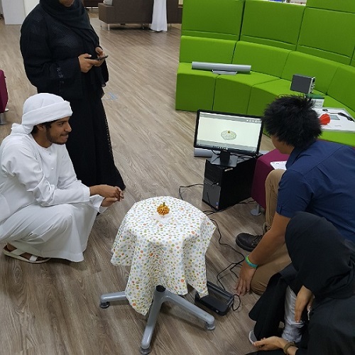
● We scanned a human as well, and got amazing results in terms of the solidity of the model for each of the scans. We used a rotating stool to place the objects on and scan without moving a bit. My scan in particular was not that great but got some positive results.
● You can think of scanning as a sort of physical photography. By scanning a physical object, you can create a 3D digital model. Unlike traditional photography, however, you can use the digital model to return to the physical mode by sending the image to a 3D printer.
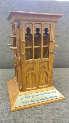
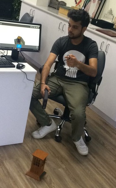
I scanned an arabic structure as well
● The Sense 3D scanner gives you the ability to observe a scene in three dimensions and then translates the observations into a 3D model. You can then use various Geomagic applications to translate the scans into information such as:
1. Select what to scan, an object or a person.
● If you select Object, choose the appropriate object size.
● Small objects: less than 16 inches
● Medium object: less than 40 inches
● Large objects: less than 80 inches
If you select Person, choose either Head or Full Body.
my steps to use the sense scanner:
● Click Start Scan.● You have approximately 3 seconds to get in place to start your scan.
● Hold the scanner approximately 15 inches away from your subject, and ensure that the image is centered on your computer screen.
● Slowly and steadily move the scanner around the subject while viewing the image on the screen.
● Edit tools
● Use the Erase tool to remove unwanted portions of your scan. Move the cursor over the area that you want to erase, and then let go of the mouse button; the unwanted portion will be removed.
● The Solidify tool will make your scan print-ready by filling in all the holes and closing the model to make it solid
● Enhance tools
● To automatically enhance brightness, contrast, and clarity in your scan, use the Auto Enhance tool.
● To remove unwanted areas, click the Trim tool and drag the cursor over the area you want to slice away. The tool always removes the smaller of the two pieces and deletes the smaller mass.
● To improve the look of the scan, click the Touch Up tool and drag the cursor over the area you want to improve.
● Share tools
●To save your scan to your computer, click Save. You can save the scan as an stl, ply, or obj file format;
the formats will work in any 3D modeling software. If you have a 3D printer available on your network, you can choose
a printer and open the saved file with the printer’s client software. I saved an .stl file for myself.
Links & Models
● Download Blender on the link below, it is of the best open source and very user friendly 3D modeling and animation software.
● Download Cura on the link below, the open source slicing software, powered by Ultimaker.

● Also check out the highly recommended sketchfab, online platform to upload 3d models. Visit SKETCHFAB
● Download the 3D Cube Blender file (.blend) HERE
● Download the 3D Print (.stl) file HERE
● Download the 3D Scan for Fake Plant(.stl) file HERE
● Download the (.stl) file for 3D Scan Arabic Structure test HERE
weekly progress
about the dubai mini maker faire
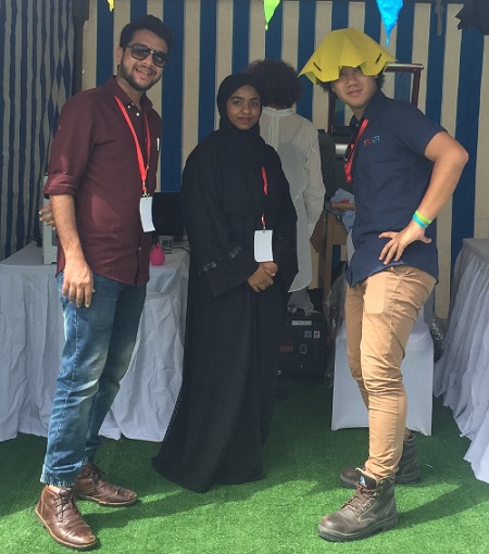
winning the hackathon prize for the saviour bracelet.