TASKS TO DO-Read a microcontroller data sheet
Program your board with as many different program languages and programming environments as possible
Compare the performance and development workflow from other architectures
This weeks assignment is to read the datasheet of a board and program it to do something.In the
electronics design week we have already designed and milled a board(echo helloworld board added with switch and led) with
ATtiny44 microcontroller.I am from a Civil engineering background and most of the things are new to me so before reading the datasheet of
Attiny44 microcontroller let us check what is the basic difference between microcontroller and microprocessor is:
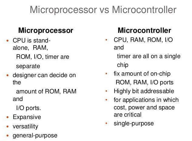
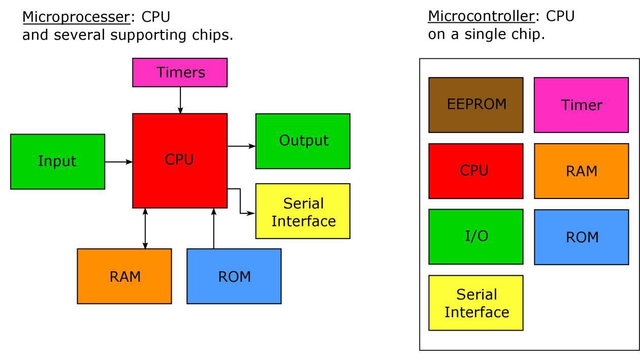
The basic difference between microprocessor and microcontroller is that microprocessor has only the central processing unit(CPU) with it and
all the external peripherals like ROM,RAM has to be added to it while a microprocessor has all these embedded in it.
you can download ATtiny44A datasheet from this webpage
Reading Datasheet is a very hectic job,each and every term was new to me,nothing got into my head.After reading one word I have to
google it out or ask my Instructor to know what it is.The datasheet has a lot of information about the microcotroller. We can know the pinconfiguration of the chip,ports, operating voltage,
clock frequency,different registers which are the basic things needed for programming the board using this chip.
ATtiny44A
Attiny 44A is the high performance 8bit AVR RISC based architecture microcontroller by Microchip.
It is having 4KB ISP flash memory,256 Byte EEPROM, 256B SRAM,12 general purpose I/O ports, 32 general purpose registers,
an 8 bit timer/counter with two PWM channels,a 16-bit timer/counter with two PWM channels, internal and external interrupts,
Analog to digital converters,programmable watchdog timer with internal oscillator, internal calibrated oscillator.These are the information we get from the
first page of the datasheet.
Block diagram of ATtiny44A
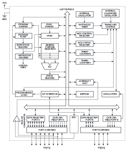
AVR
AVR is a family of microcontrollers developed by Atmel whose parent company is microchip.These are modified Harvard architecture 8-bit RISC single-chip microcontrollers.
AVR was one of the first microcontroller families to use on-chip flash memory for program storage, as opposed to one-time programmable ROM, EPROM, or EEPROM used by other microcontrollers at the time.[wiki]
RISC
RISC is reduced Instruction Set Computer used in Microcontroller to optimize its performance and
acheive low level operation in a single clock cycle by reducing the cycles per instruction at the cost of the number of instructions per program.
Memory
Memory is an area where code and instructions are stored.
Normally 3 types of memory present in a microcontroller. These are SRAM, FLASH, and EEPROM memories.
Registers
Registers are small memory elements in microcontrollers normally with 8bit capacity.
Registers can be accessed quickly by the ALU of microcontrollers.In our processor the ports are assigned input/output values using registers.
PINS and PORTS IN ATtiny44A
From this pin configuration diagram we can see that there ar two ports PortA and PortB,the various pins for supply voltage,ground,and other connections.
VCC - supply voltage
GND - ground
PortA(0-7) -Port A contains 8 pins from 0 to 7 with internal pull up resistors
PortB(0-3) -Port A contains 4 pins from 0 to 3 with internal pull up resistors
RST-reset
SCK-serial clock
MOSI(master-out-slave-in)-Communication from In-System Programmer (Master) to target AVR(Slave) in the microprocessor.
MISO(master-in-slave-out)-Communication from target AVR(Slave) in the microprocessor to In-System Programmer (Master).
PORTS
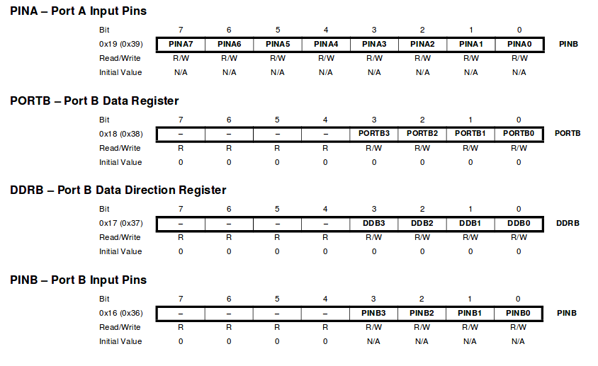
DDRx is an 8-bit register which stores configuration information for the pins of Portx.
Writing a 1 in the pin location in the DDRx makes the physical pin of that port an output pin and writing a 0 makes that pin an input pin.
PINx is an 8-bit register that stores the logic value, the current state, of the physical pins on Portx. So to read the values
on the pins of Portx, you read the values that are in its PIN register.
PORTx is an 8-bit register which stores the logic values that currently being outputted on the physical pins of Portx if the pins are
configured as output pins. So to write values to a port, you write the values to the PORT register of that port.
[explanation reference-www.avr-tutorials.com]
Programming the Board
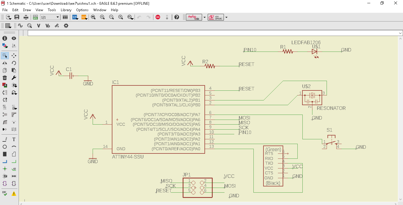
For programming,we are using the echohelloworld board which we have milled in the electronics design week with an additional led and switch.
So the programming part mainly includes with the switch and led.We can blink the led,light it up when switch is pressed etc.For programming I am using ArduinoIDE and C language.
This is the schematic diagram of the Echohelloworld board I designed during the electroics design week
USing Arduino IDE
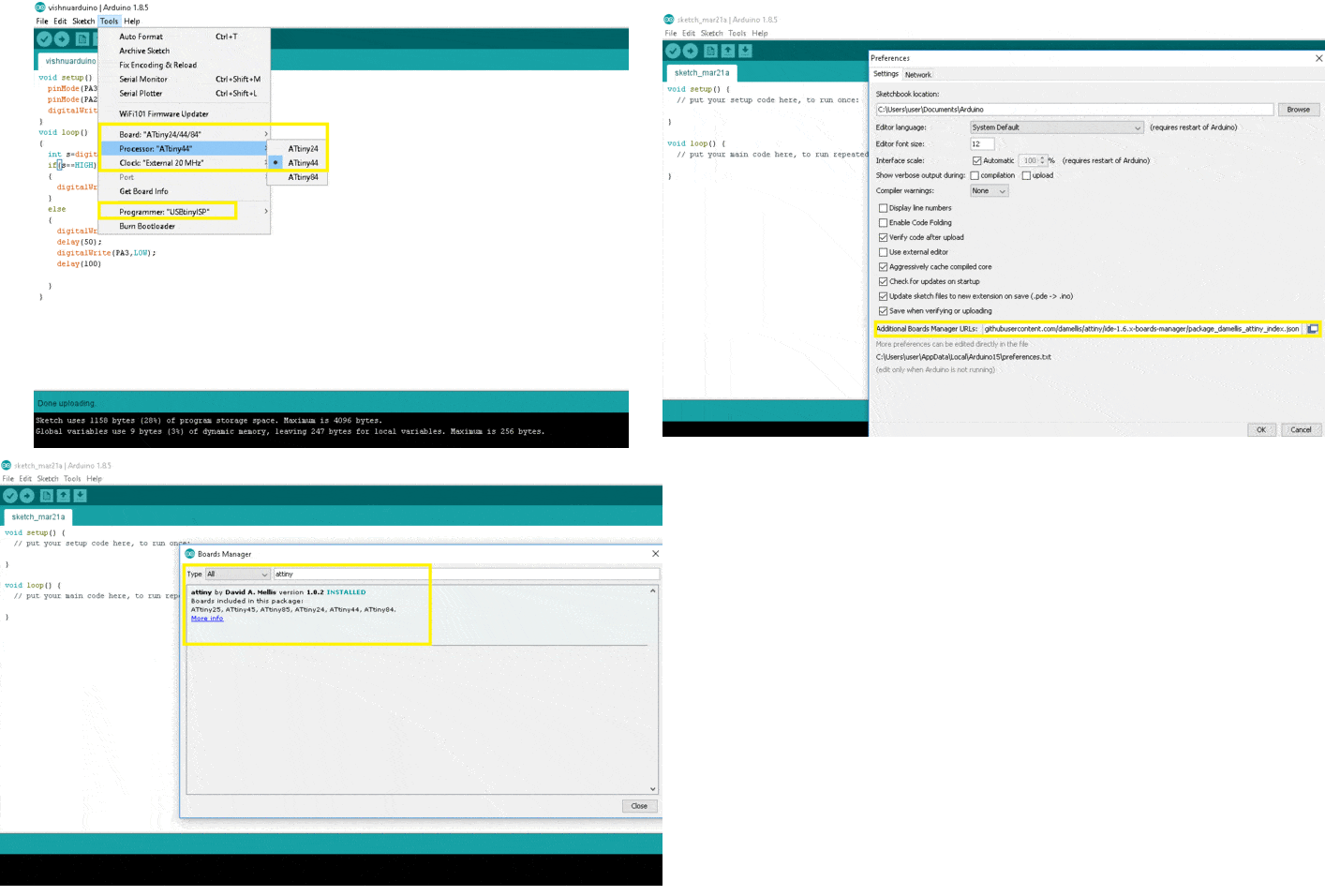
I am using ArduinoIDE in windows.In Arduino we have to include the ATtiny44 chip librarys first.
So the steps to include it are as follows:
1) Open arduinoIDE and click File>preference>setting>Click add board manager. Enter the following link. click ok.
https://raw.githubusercontent.com/damellis/attiny/ide-1.6.x-boards-manager/package_damellis_attiny_index.json
2)After adding the link click>Tools>board>board manger> Select attiny and click install. Now we had added the attiny library.
3)Now we we have to select the programmer,board,processor and clock in the tools menu.
programmer-USBtiny
board -ATtiny24/44/84
processor -ATtiny44
clock -External 20MHz(as we have used in our board)
Program 1
First I am writing a program to light an led when the switch is pressed.I haven't added a resistor to the switch
So first I have to Pullup the switch.
Here is a small video clip of that:
Program 2
In this program I wanted to blink the led 10 times when the switch is pressed once.I used a for loop
for attaing this result
Here is a small video clip of that:
Program 3
Now I want to program the board for a latch switch.The led gets on when switch is pressed
and get off only when the switched is pressed again
Here is a small video clip of that:
Using C programming language
The C programming part was done on linux.For this we have to write our program in any text editor,I used atom for writing the program
After writing the program we have to save the file as .C file.After that we have to open the terminal and create the hex file and we have to flash the
.hex file.
Including libraries in C
#include <.avr/io.h> :- This header file includes the apropriate IO definitions for the device
#include<.util/delay.h> :- This header file includes the function short delays in the program execution.
define F_CPU 20000000 :- Since we connected a 20MHz crystal into the circuit
Programming steps with .c file
The programming steps using AVR GCC compiler is mentioned below.
Open the terminal and enter the following commands.The first command creates OBJ file,
second creates ELF file and the third command creates HEX file. Now using the HEX file, the program can be flashed to chip using the below command:
Program 1
In C also i am trying a program for led blinking to start with.
Program 2
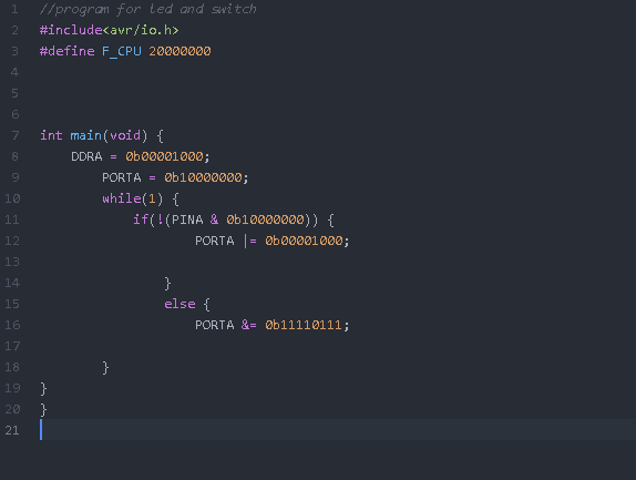
This program I am trying with switch and led.I am using atom for writing the code.After writing the
code run the commands for making the HEX file and using it flash the program to the board.
Group Assignment For the group assignment we have to compare the performance and development workflow from other architectures.We were unaware of different architecture
and a small study was conducted. PIC Microcontroller
PIC is a family of microcontrollers made by Microchip Technology.
PIC micro chips are designed with a Harvard architecture, and are offered in
various device families. The baseline and mid-range families use 8-bit wide data memory,
and the high-end families use 16-bit data memory. The latest series, PIC32MZ is a 32-bit
MIPS-based microcontroller. The PIC architecture was among the first scalar CPU designs and is
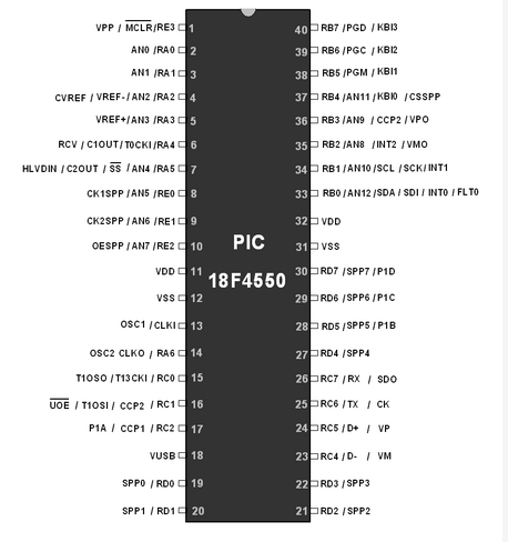
still among the simplest and cheapest. PIC18F4550 device in PIC18 family. PIC18F4550 is an 8-bit RISC architecture microcontroller.
Its specifications are:
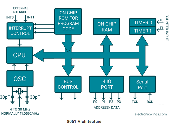
Timer: One 8-bit and three 16-bit Timers i.e. Timer0-Timer3. 8051 Microcontroller The 8051 is the first microcontroller of the MCS-51 family developed by Intel Corporation in 1980.
It was developed using N-type Metal-Oxide-Semiconductor (NMOS) technology, and later it came to be
identified by a letter C in their names, e.g. 80C51 which was developed with Complementary Metal-Oxide-Semiconductor (CMOS)
technology which consumes less power than NMOS and made it better compatible for battery-powered applications. Raspberry was taught to us by our fabmate Amith as he usually teach these stuffs in his school.
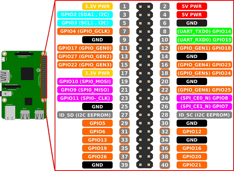
Raspberry pi is small single board computer that is designed to teach basic computer skill fo school students in developing countries.
Now there are wide varity of Raspberry pi models and they are used in various feild.Raspberry pi is equiped with processor of BOARDCOM,
which is of ARMv6 architecture and can be program using Python ,c java etc Amith brought raspberry pi board to our lab and he showed us led blinking using python programming.Loved it and planning to buy one in future.
avr-gcc -g -Os -mmcu=attiny44a -c (name of file).c
avr-gcc -g -mmcu=attiny44a -o (name of file).elf (name of file).o
avr-objcopy -j .text -j .data -O ihex (name of file).elf (name of file).hex
sudo avrdude -c usbtiny -p t44 -U flash:w:(name of file).hex
program for blinking
making .hex file from .c file
flashing the .hex file
programwith switch and led
USART: 1 In-built Enhanced USART.
ADC: 10-bit 13 channel ADC.
Capture, Compare and PWM module (CCP) and Enhanced CCP module.
USB: USB V2.0 support transfer speed 1.5Mb/s to 12Mb/s.
Master Synchronous Serial Port (MSSP) having I2C and SPI protocol.
256 Bytes of EEPROM, 32Kbytes of Flash memory and 2KB internal SRAM.
PORTS: A, B, C, D and E.
Streaming Parallel Port for USB streaming transfers.
Three External Interrupt.
Oscillator
Raspberry PI