Shopbot PRSalpha
Shopbot PRSalpha
TASKS TO DO-test runout, alignment, speeds, feeds, and toolpaths for your machine
make something big.
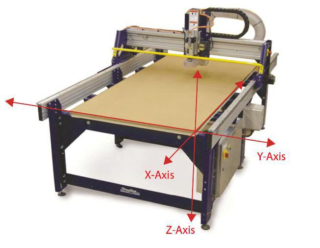
This weeks task is to make something big by using Shopbot.Shopbot is a 3-axis CNC machine which works on automation of machine tools by means of computer.The process of computer controlled machining includes creating a CAD file design,converting the CAd files into a set of codes(G-code) for the machine to understand using a CAM software.In Shopbot each time the G-code is generated and sent to the machine,this controls the location, feedrate,velocity of the process.
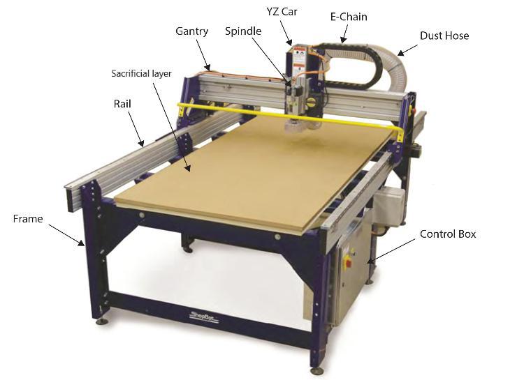
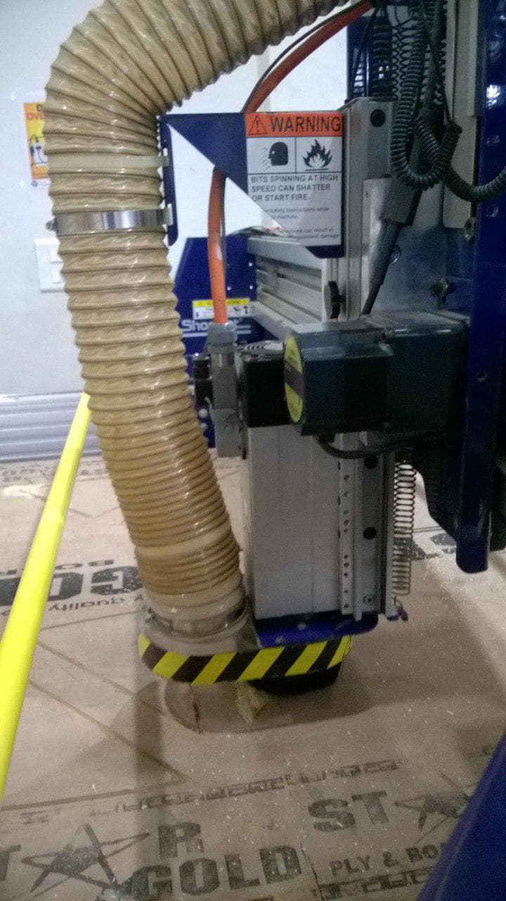
In our FabLab we have Shopbot PRSalpha model which has a bed size of 96 inch x 48 inches.It is
the biggest machine in our Fablab and has a vacuum system as well as a dost collecting chamber attatched with it.
Read more about Shopbot
Safety Precautions
Safety is very important while working with Shopbot.So here are some safety precautions that
we should follow while using Shopbot
1).Do not operate the machine alone.Have a bystander with you for the operation.
2).Be aware of the emergency stop switches
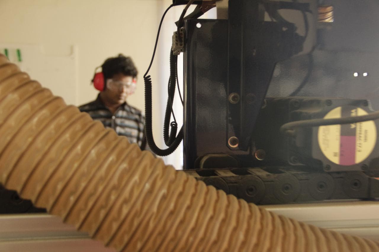
3).Eye and ear protection is mandatory while machining in Shopbot.
4).Wear shoes while machining with Shopbot.
5).Always use a sacrificial layer,otherwise it risks in breaking the bit by contact with the machine parts.
6).Never place your hand in the rail while the machine is operating,maintain a safe distance always.
7).Also it is safe to provide taps for smaller parts because after cutting they become loose and when it comes
in contact with spindle ,it can be thrown focefully in any direction.
Tooling and feeds in Shopbot
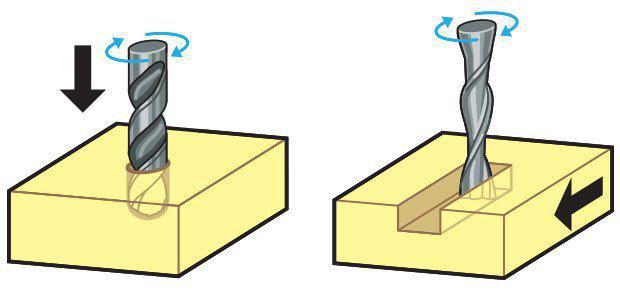
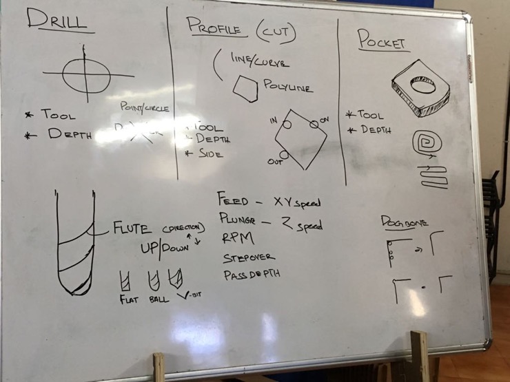
Endmill v/s Drillbit -These two are the basic tools in Shopbot.A drill bit is used to cut into the material having a teeth at the end.The main use is to drill holes while an endmill traverse the path while cutting the material,so for traversing purpose it need cutting edge in sides and they are called flutes.
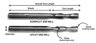
Upcut v/s downcut Endmill- upcut endmill is the one in which the flutes move upwards
as the mill rotates thus it removes the material from the bottom and takes it to the top thus it gives you a
better bottom finish, the downcut mill is the vice versa it gives better finish at the top.
Thus a good practice would be to have a shallow cut with a downcut endmill just enough so that we
get a good top finish and the rest of the milling can be done with the upcut endmill for better bottom finish.
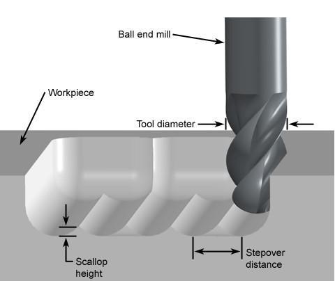
flat end mill v/s ballend mill-Flat and ball endmills- .Flat end mill has a flat bottom
while ball end mill has a rounded bottom.So when we mill on a material the flat end mill leaves some steps while a
ball endmill will gives you a smooth finish.
Chipload-Chipload is basically the amount of material removed in each chip.
It is calculated as Chipload = feedrate(inch/min) / (RPM x Number of flutes).
Cut depth - It is basically the amount of mill that should go into the material in each pass it makes.Too much
cut depth damages the mill while too less cut depth wastes our time.
Stepover-This is the amount of over-lap the endmill makes when it is traversing sideways.Usually we are using
50% as the stepover for a better finish.
Group assignment
Firstly we were given a class about the tools,profiling pocketing and the other settings in the software as well as shopbot by our instructors Yadu and lancy felix.
Tolerance test
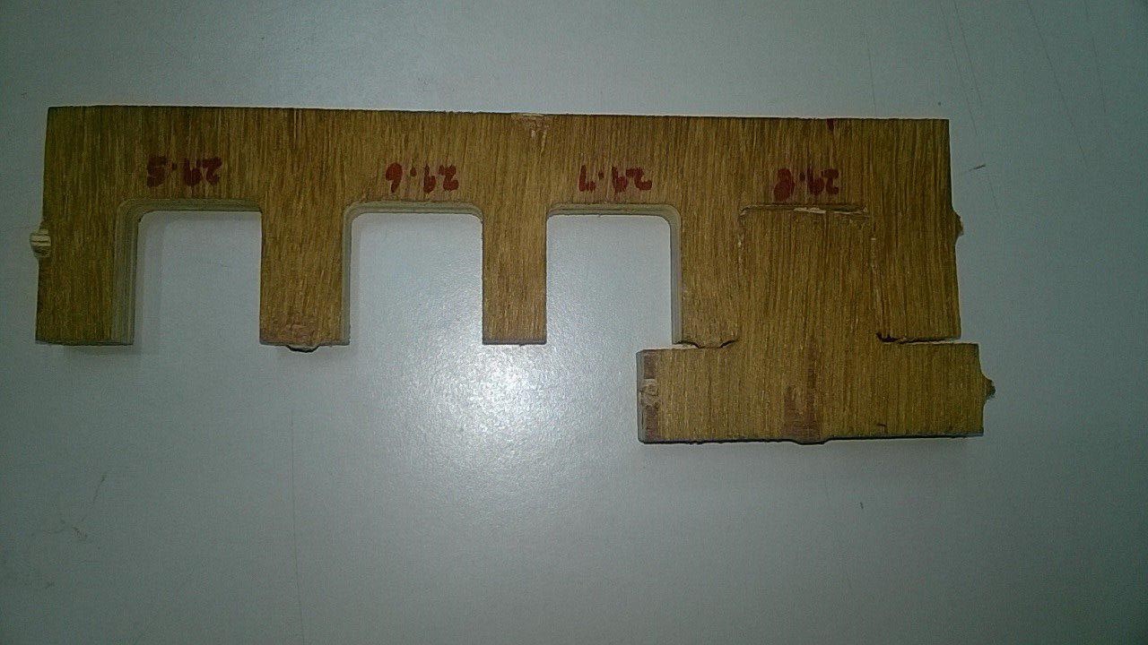
As a part of our Group assignment we decided to have a test cut to find the tolerance of the
material.We created a comb design for 30 mm block ranging from 29.8mm to 29.5 mm ,it was tight for 29.8mm and could fit in
Test for spindle speed,runout,toolpath,Alignment, Speeds and Feeds of SHOPBOT a
For testing this we cut small square shapes at varying spindle speed,feed rate and depth.Shapes with similar rpm were
clubbed together to create the toolpath.
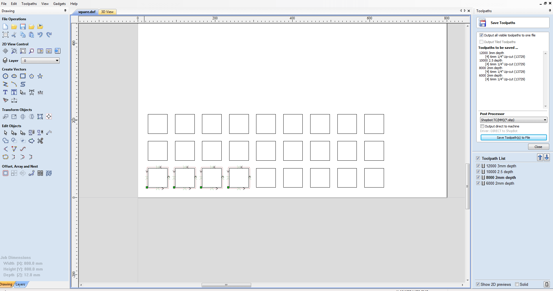
The first test was for the RPM with varying feed rate and depth.It was found out that 12000 rpm and 10000 rpm gave a good cut
of which 12000 rpm was finer.
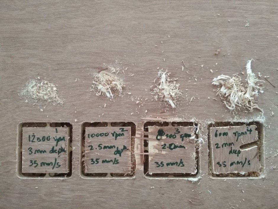
The first test was for the RPM with varying feed rate and depth.It was found out that 12000 rpm and 10000 rpm gave a good cut
of which 12000 rpm was finer and at 6000 rpm the tool got stuck and loosened.So when Rpm is decreased the quality is getting decreased
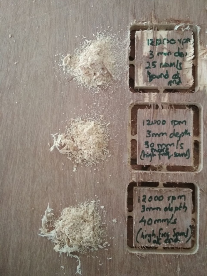
The next check was for the feedrate we choose 12000rpm for testing and found out that at higher feedrate high frequency noise was heard.
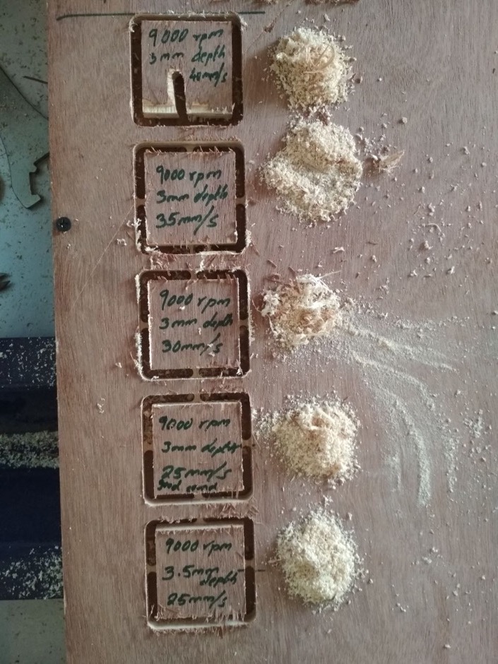
So after discussing with our instructor we decided to have a final test with 9000 rpm at varying feedrate and we got the best result
for 9000 Rpm,25 mm/sec feed rate and 3mm depth.It was also having the normal sound amoung these.
ForRunout a circle was cut and the measurements were taken at different points.Runout happens due to the inaccuracy of the
rotary system (tool diverting slightly from the axis).This may be due to the problem with tighting the tool,wear and tear of the assembly,vibrations etc.Runout is
calculated as the average of the maximum and minimum measurements we get
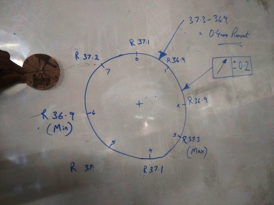
The runout was calculated to be 0.2 mm
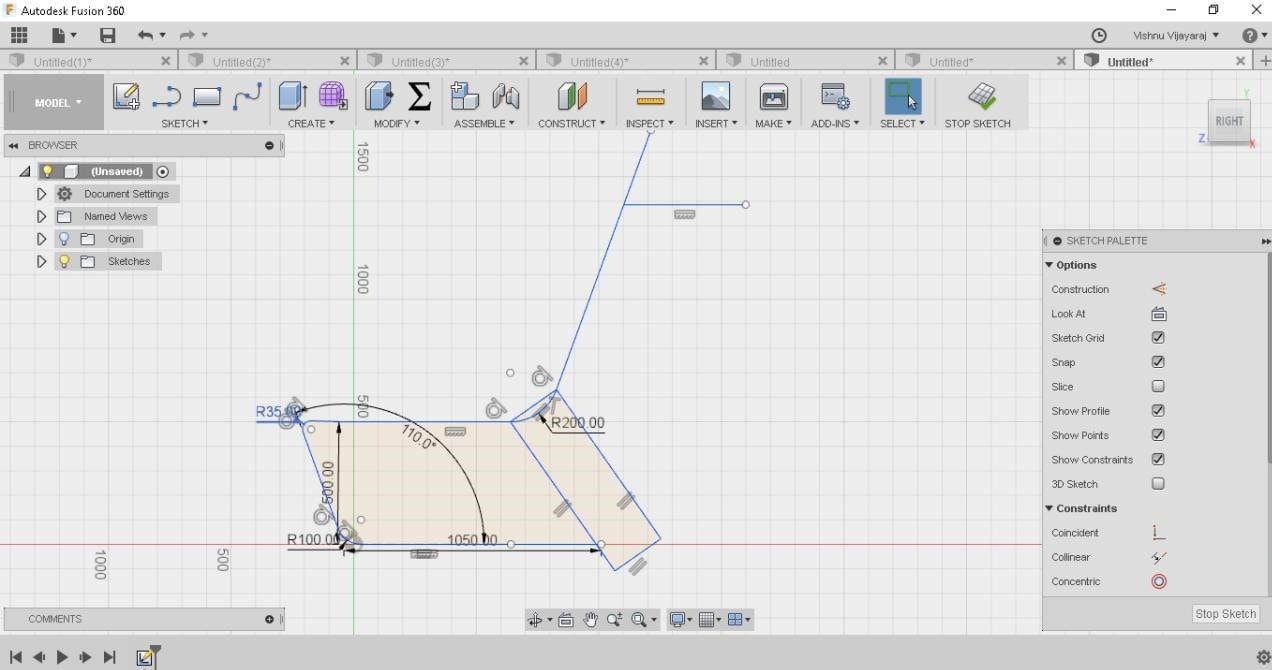
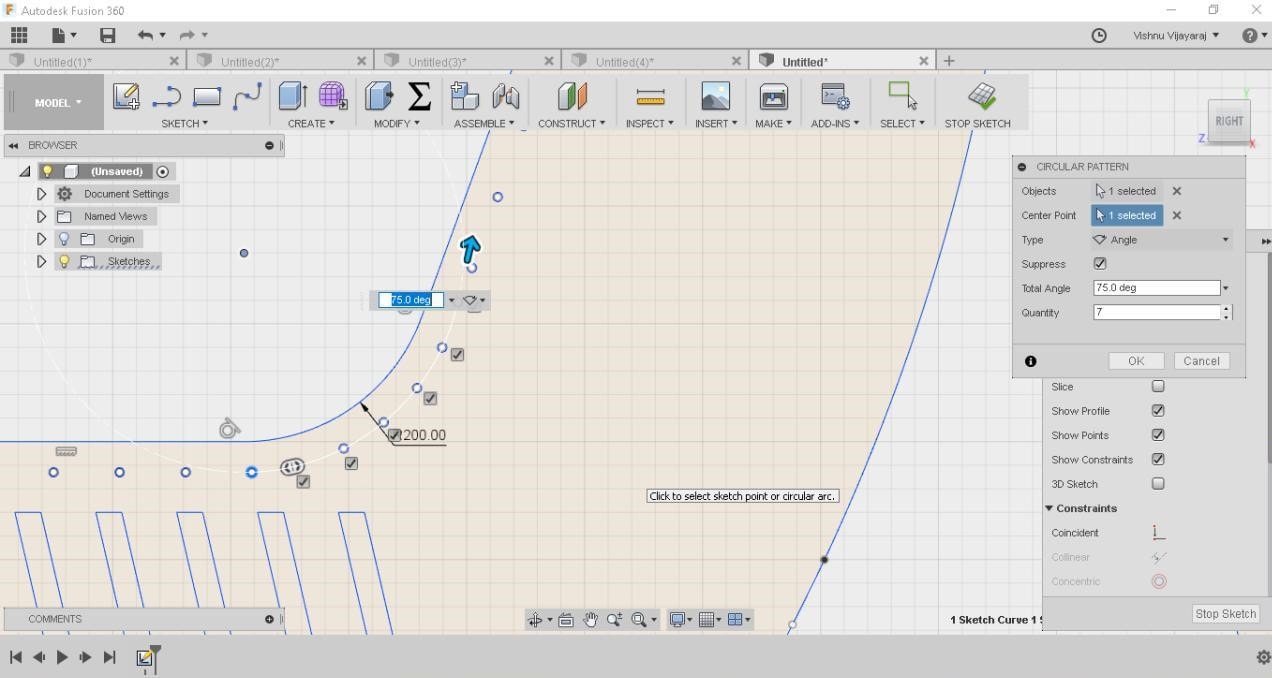
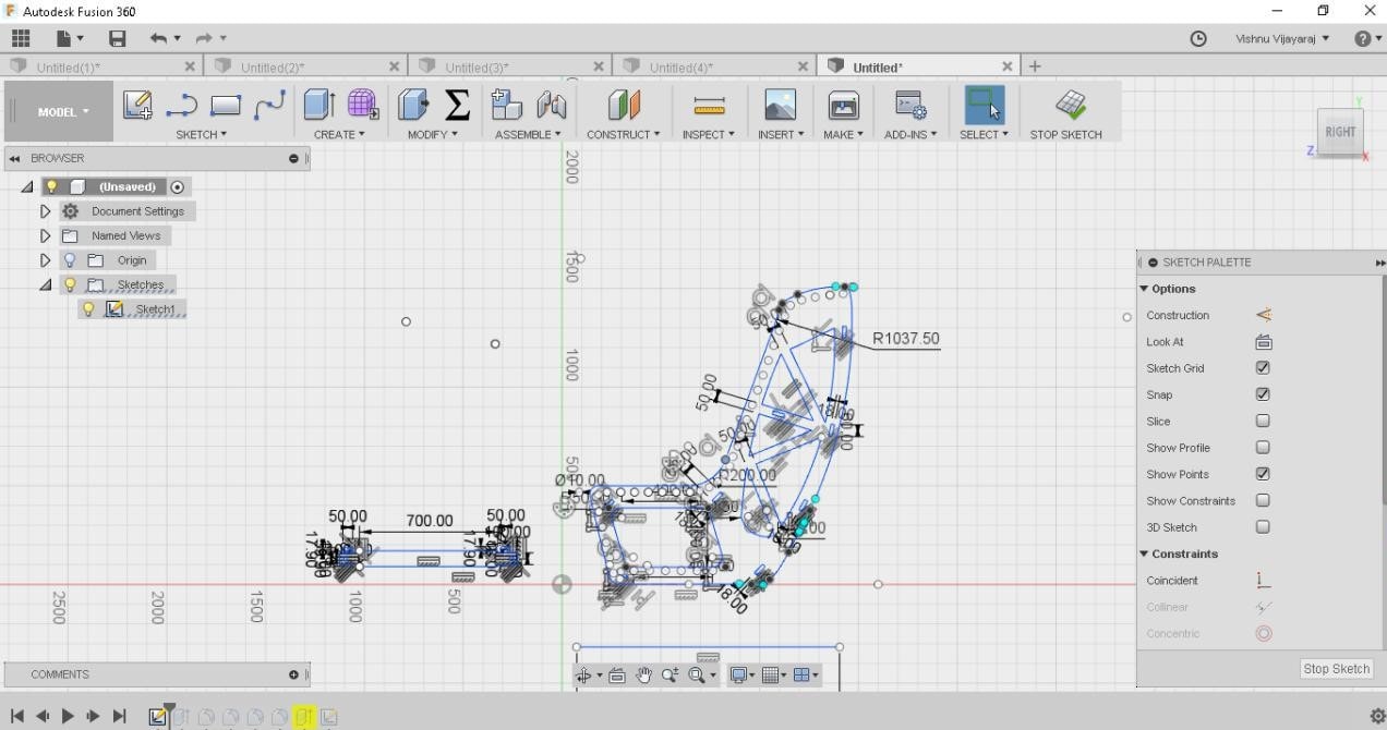
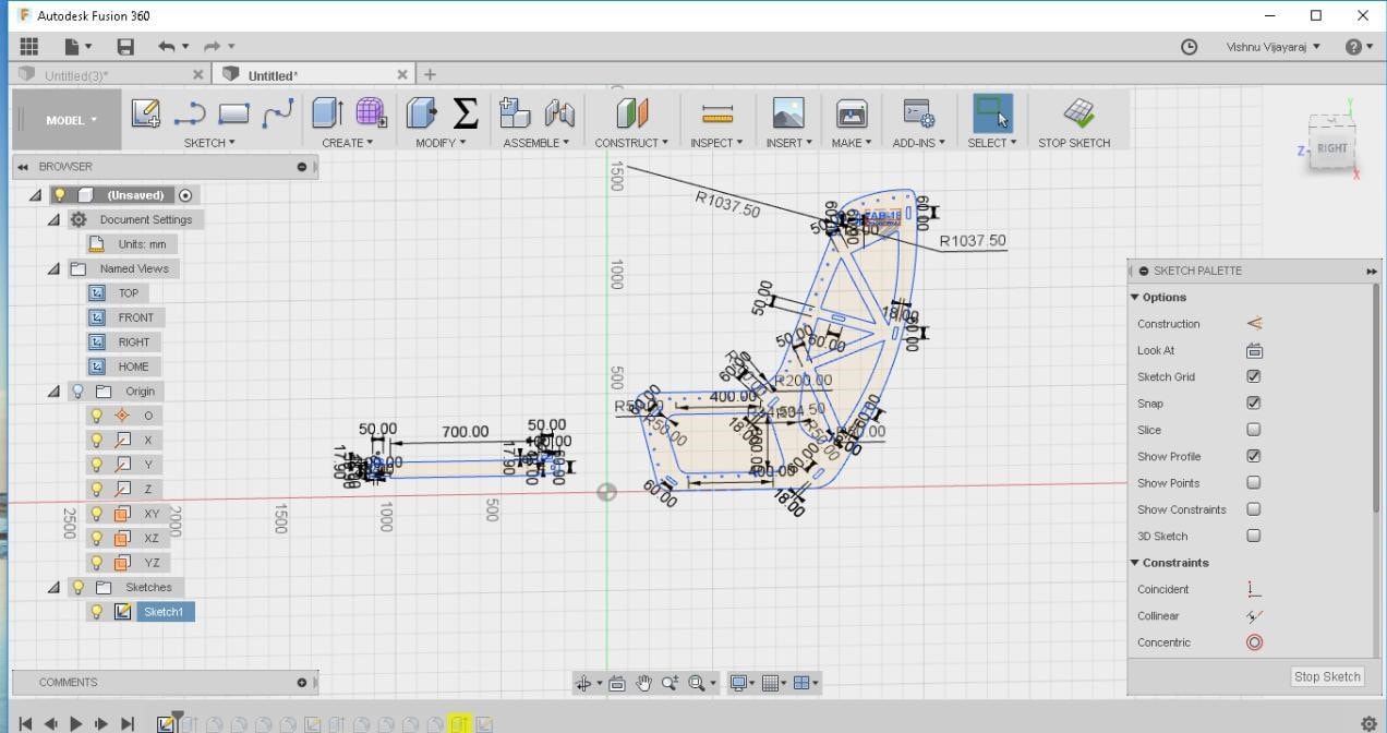
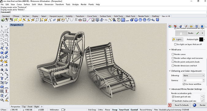
Designing something big
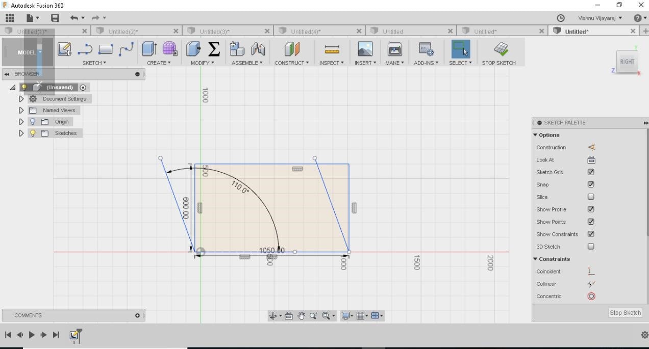
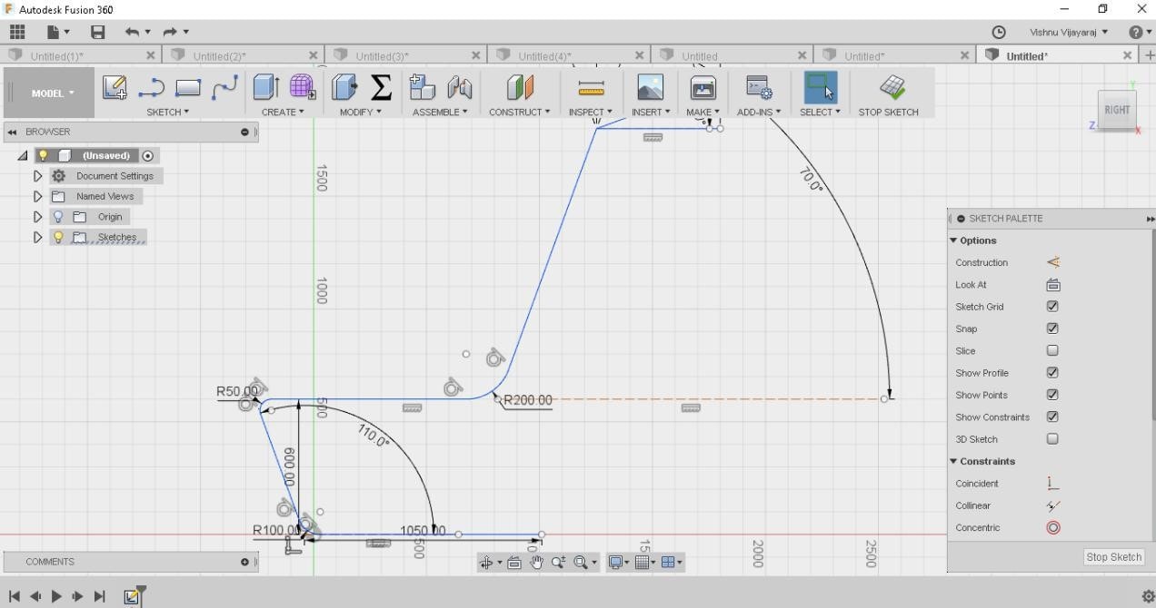
For designing I used Fusion360 software as usual.The main problem was to design what?.
Every time I change my mind,skipping from one design to another.I tried to design a sofa, a shelf and atlast ended
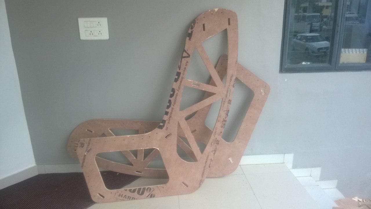
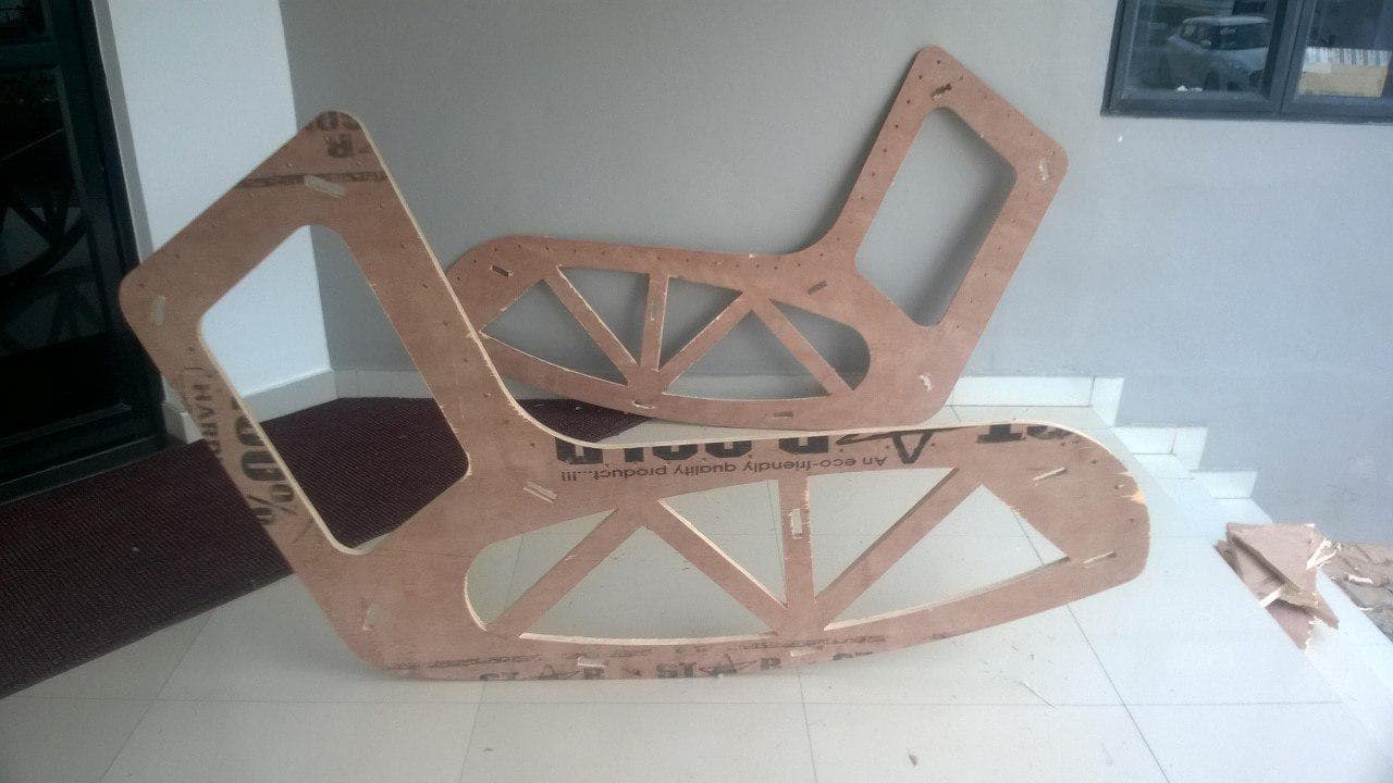
up in a chair.My model is very much inspired from pinterest, a chair having frames cut out from plywood and seating
managed by means of rope.It can be used as a rocking beach bed when tilted 90 degree.
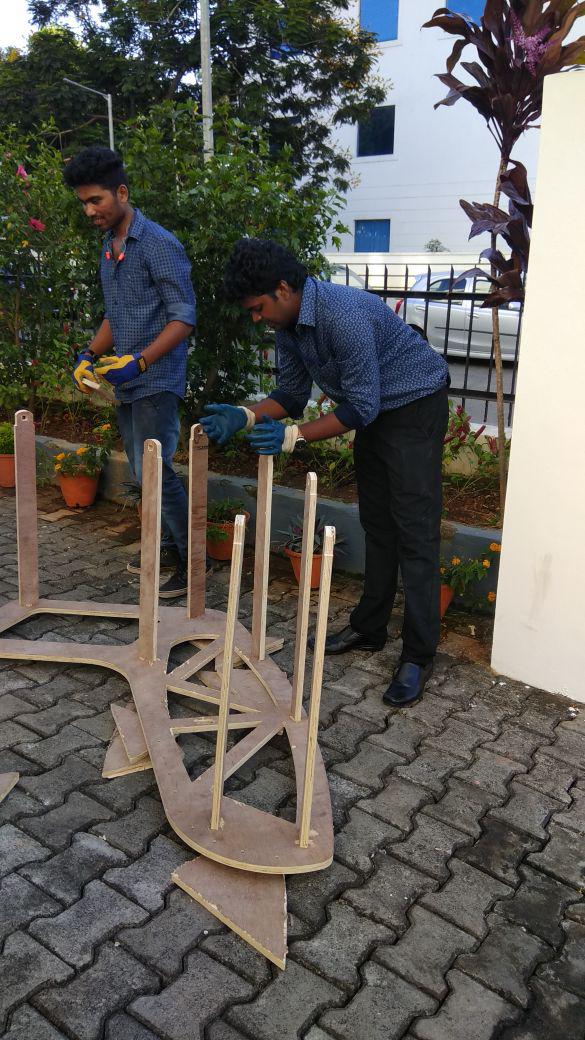
The buiding stages of my model is shown below:
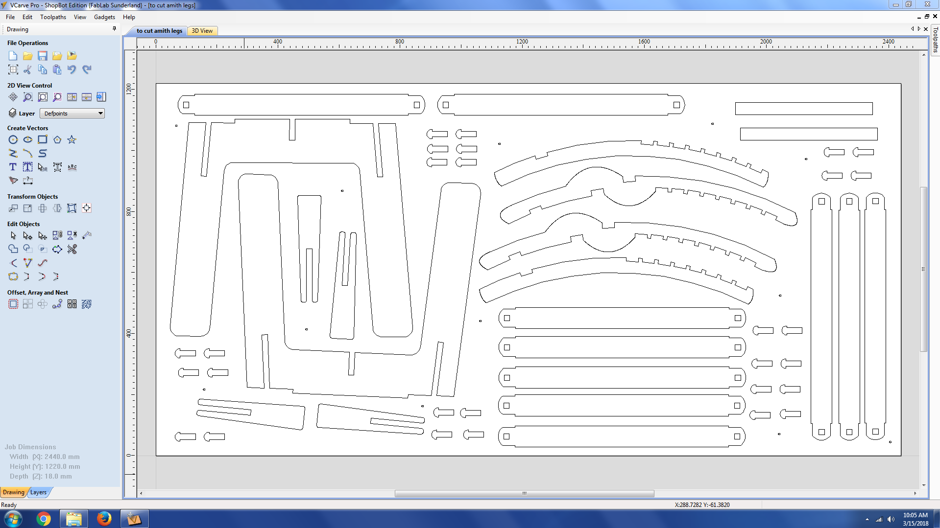
V CARVE PRO
V carve pro is a software for cutting parts on Shopbot CNC router.It generates the toolpath for shopbot from our design files(.dxf)
We can select different operations such as cutting,drilling,pocketing in V carve.
Problem
I have designed In fusion 360 and while exporting one part of the design was missing.I rechecked opening in Rhino and Autocad but in that full design can be opened.
There was some error happening while exporting to Vcarve from fusion so I opened the design on Rhino set up my design in the bed size and imported to v carve.
Now the full design came.
I needed a full sheet for cutting the frame of the chair and for the connectors i have to club it with my friend Akhil hari's design as we
both are using 18mm plywood.I now imported my design to V carve before that set the job size to 2440mm x 1220 mm .The next step is to create tooplpath for shopbot for machining our design.
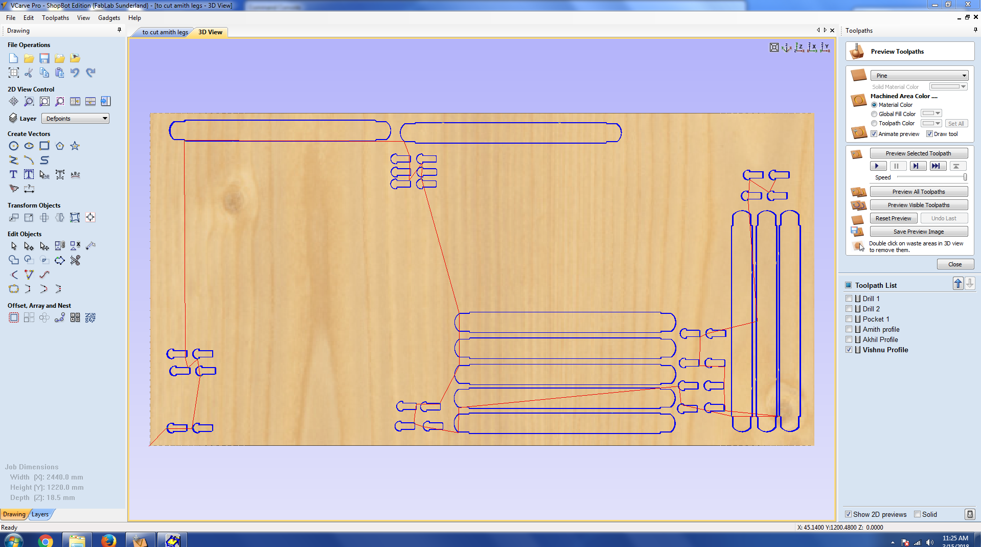
In this we have to create seperate toolpath for pocketing, drilling,cutting operations.
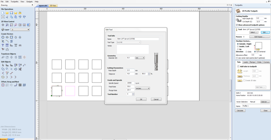
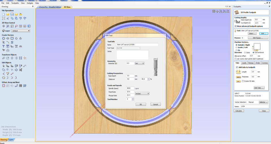
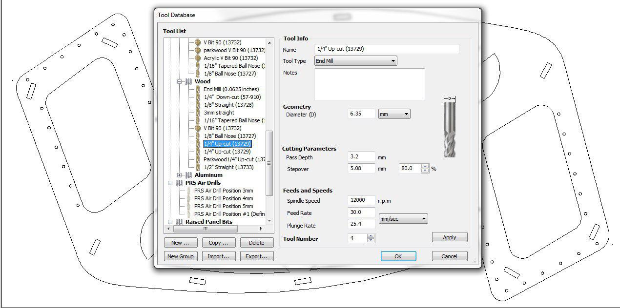
I decided to create toolpaths for the outer frame ,inner design cut ,holes and connectors.For all the toolpaths I chosed 6mm (1/4th inch upcut bit)
Problem
While selecting the components for making toolpath I noticed there were multiple copiesof my components in the design and parts where broken of the components.
The broken parts were fixed by using the join tool, but the multiple copies I have to sit and delete.
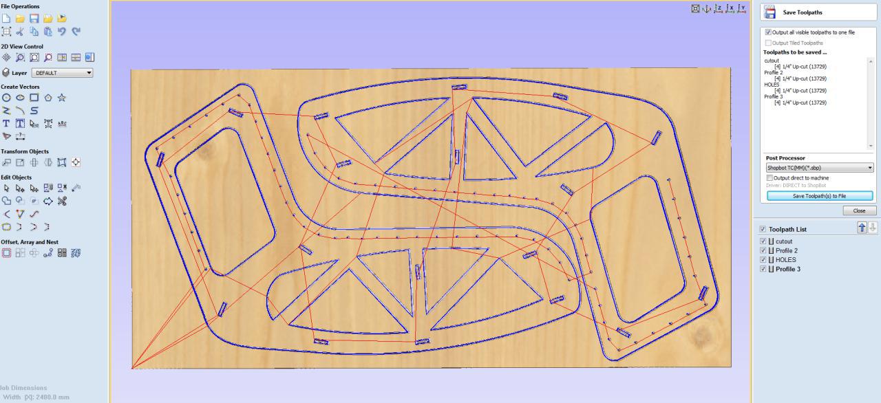
Steps in selecting the toolpath
Now I have to set each toolpath.I used cutting and pocketing operations.the basic steps are as follows:
1)Provide the cutdepth -The thickness of the plywood in our lab varies from 17.9 to 18.7 so i gave the cutdepth as 19.0 mm
2)Add tabs if we are using the cutting operation so that after cutting the parts will not come out.
3)Also while cutting slots for pressfit give dogbone joints at the corners for smooth movement of the endmill.
4)Now select the components in the operation and click calculate.
5)A preview will be available
6) After selecting the toolpath we can set which part we have to cut first.I chosed all the inner parts to complete first
and then the outerpart so as to avoid any movement of the material.
Now after creating all the toolpaths,save the file as .sbp format .This is the G-code for shopbot.
Setting up the machine
Firstly, we have to ensure that the workbench is clear and place our plywood on to the workbench.
Check the levels of the plywood and screw it to the sacrificial layer to prevent rattling of the material after cutting
After turn ON the machine from the control box,and a shopbot control window appears.We can move the head in XY direction
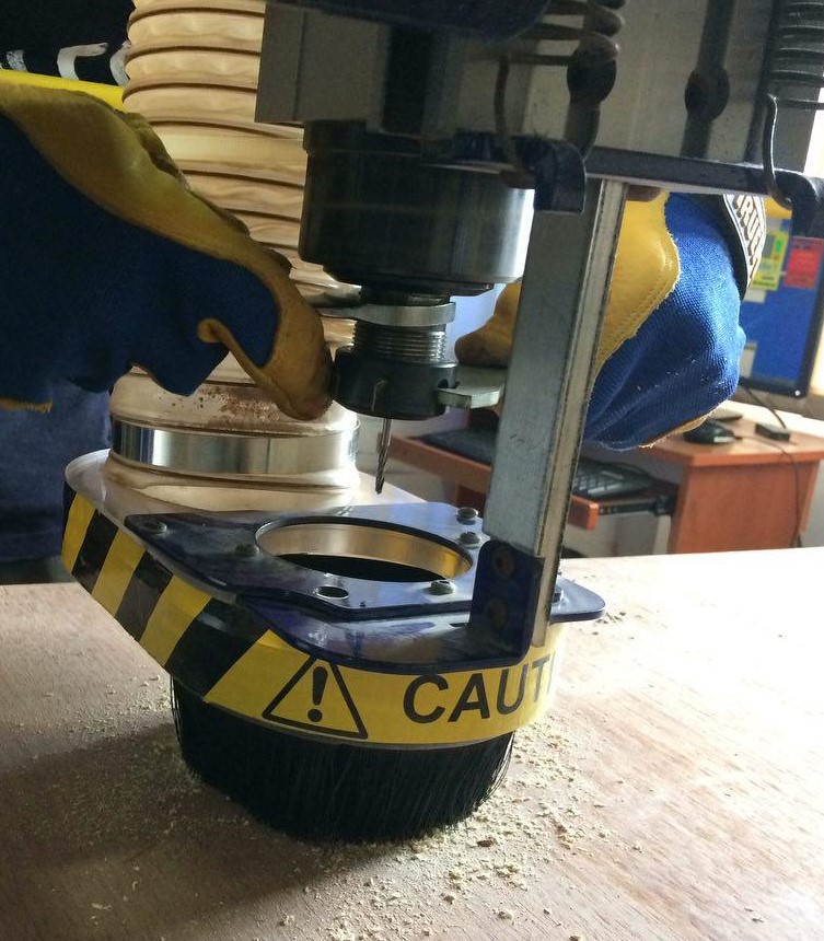
move the spindle to home position and now we have fix the bit,collet and covernut.
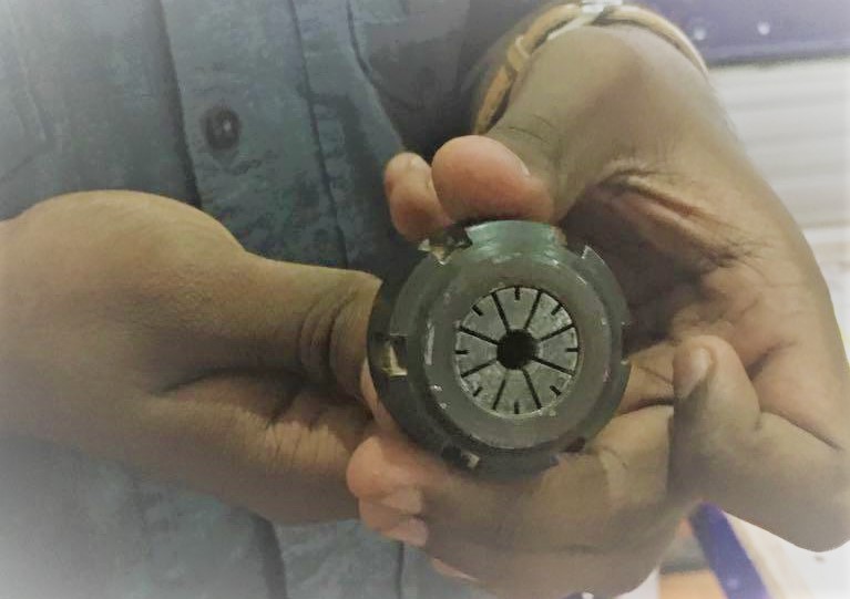
After fixing the bit the collect can be placed on the spindle using the tooth holder and wrench(clockwise for loosening and anticlockwise for tighting).For this we have to lower the dust collecting skirt
covering the spindle by loosening the thumb screw.
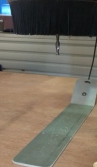
Now move the spindle to a position to set the XY as 0.Now we have to set the Z to zero.There are two methods to set Z axis to 0,either do it manually using trial and error method or use the Z zero aligning plate which is electrically connected to the shopbot.
So the zero is set and we can start machining.Select the cut part and start milling.There will be checks for warning for starting the spindle.We have to turn the key and
press the start button on the ESTOP dongle ,now press ok and the machine starts milling.Wear the protective gears and switch on the dust collector.
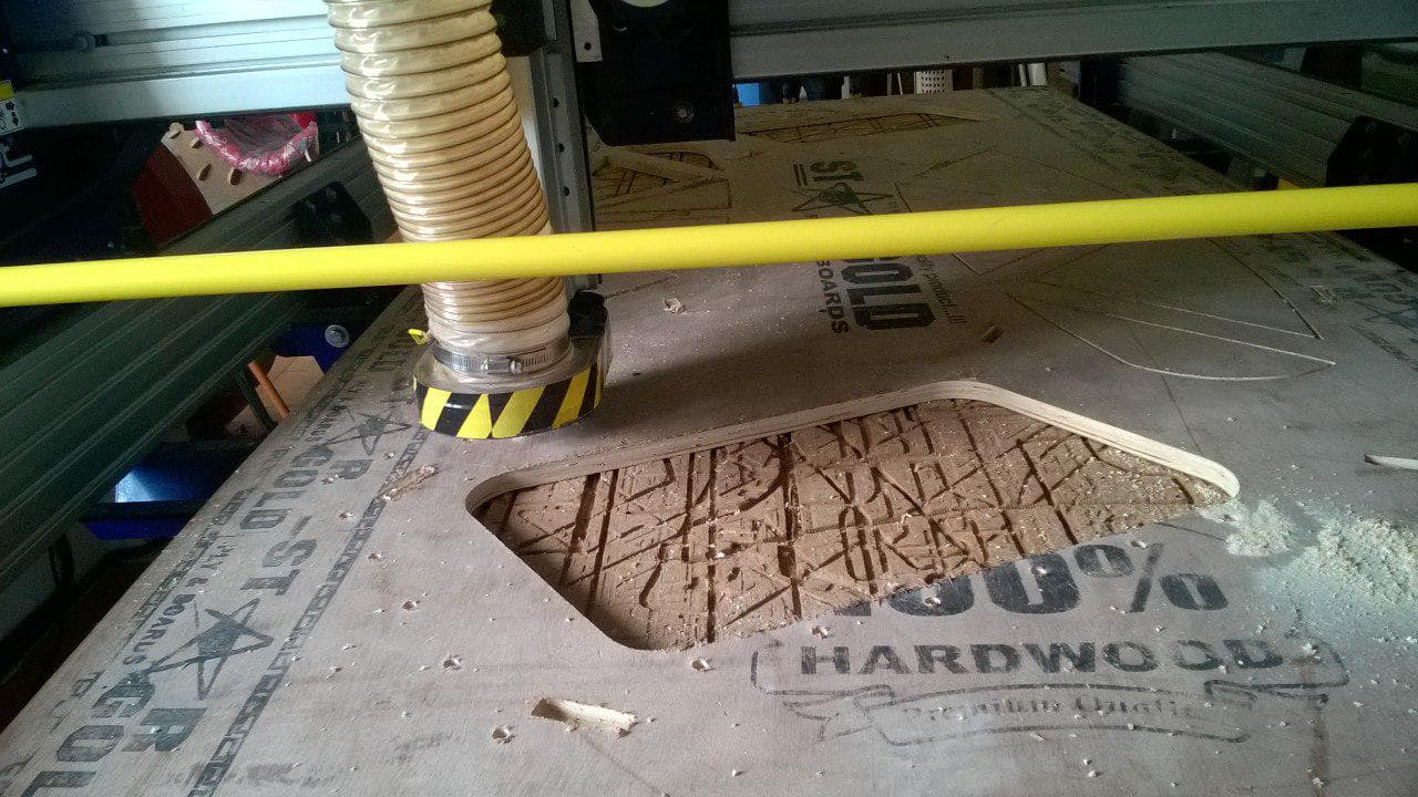
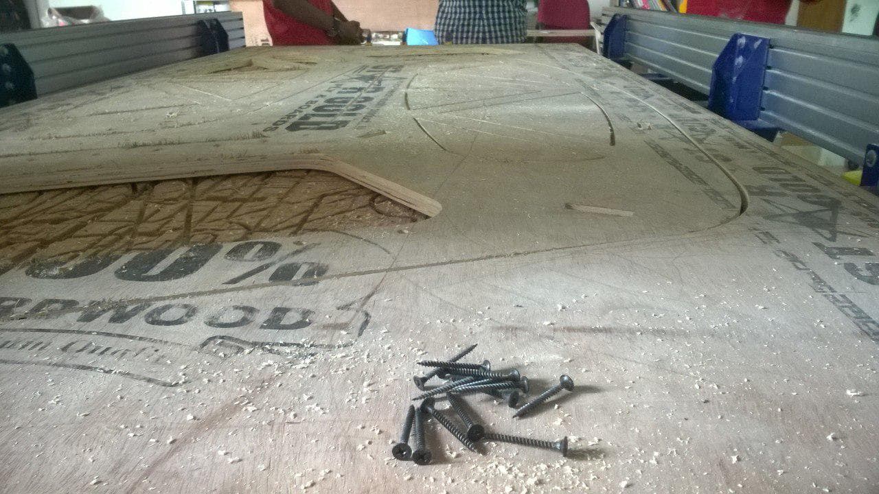
Due to some bend in the plywood some of my parts didint cut fully so i have to use some manpower to cut and file the framework .Now I have to cut the connectors clubing with my fellowmates design parts.
So the next day my chairs connectors was cut along with akhil hari's and amith remaining parts,we clubbed altogether in a single 18mm sheet and cut it.
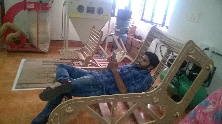
After cutting the connectors it is time for assembling the parts and finishning jobs.
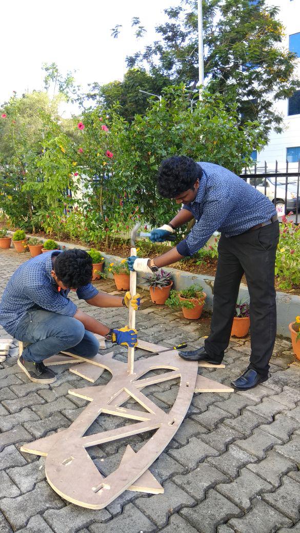
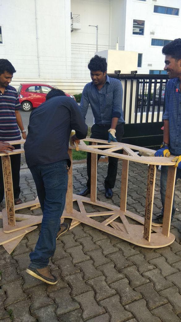
Rops were used to provide the seating.The weaving process took 3-4 hrs to finish and at last the chair-bed dual version is done.
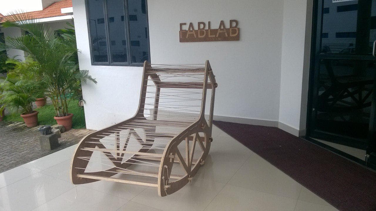
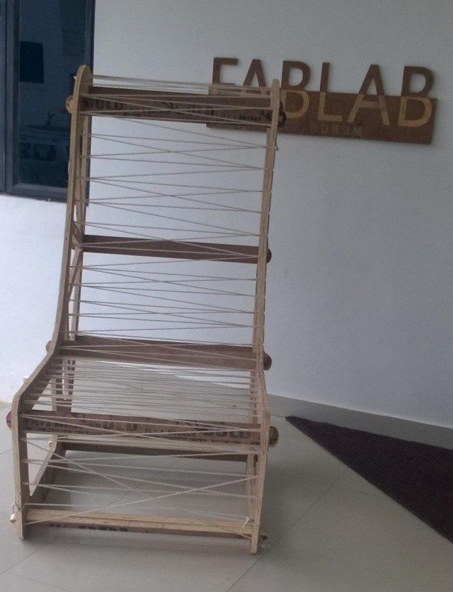
IN USE
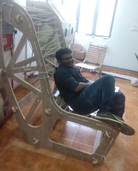
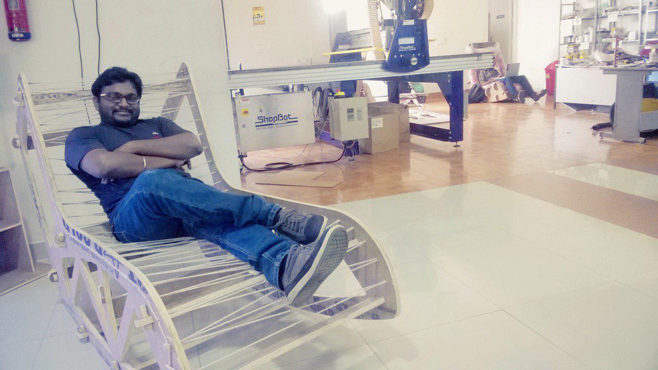
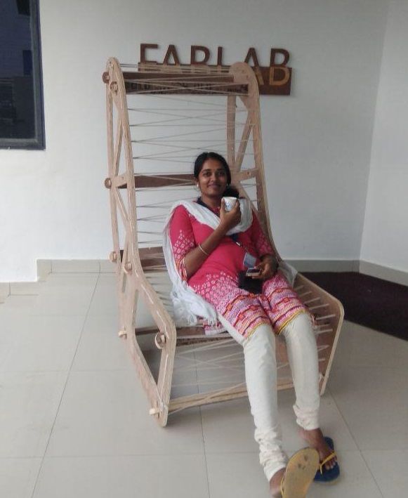
My experience This was the first time I am buiding something big.There were many problems faced
during this week.The export error happening from fusion 360 slowed down the pace of this week.Also the quality
of plywood was poor.Anyway after building this project I am happy.I thank all my fellowmates and Instructors in Trivandrum Fablab
for helping me in the buiding stages.