TASKS TO DO-TEST THE DESIGN RULES OF YOUR 3D PRINTER.
DESIGN AND 3D PRINT AN OBJECT THAT COULD NOT BE MADE SUBTRACTIVELY.
3D SCAN AN OBJECT AND OPTIONALLY PRINT IT.
3D PRINTING
3D printing is the process of making three dimensional solid objects.It is an additive process the object is created by laying down successive layers of material which can be seen as thin sliced horizontal cross sections of the object which is to be created during the process.
Unlike the other CNC machines,3D printing is an additive manufacturing process while others are subtractive where the material is cut down to get the final product.
The main use of 3D printing comes in the case of rapid prototyping.Its
fame been growing worldwide day to day and are used in the fields of
architecture,product design,dental,medical,fashion etc
Types of 3D printing Technologies
Eventhough the principle of 3D printing is additive manufacturing there
are different manufacturing processes.The American Society fot Testing
and materials(ASTM) have classified them into 7 categories,namely:
1)Vat Photopolymerisation (Stereolithography (SLA),Digital Light Processing (DLP),Continuous Liquid Interface Production (CLIP))
2)Material Jetting
3)Binder Jetting
4)Material Extrusion (Fused Deposition Modeling (FDM),Fused Filament Fabrication (FFF),Contour Crafting)
5)Powder Bed Fusion(Selective Laser Sintering (SLS),Direct Metal Laser Sintering (DMLS))
6)Sheet Lamination
7)Directed Energy Deposition
Fused Deposition Modeling(FDM)
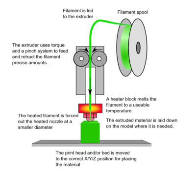
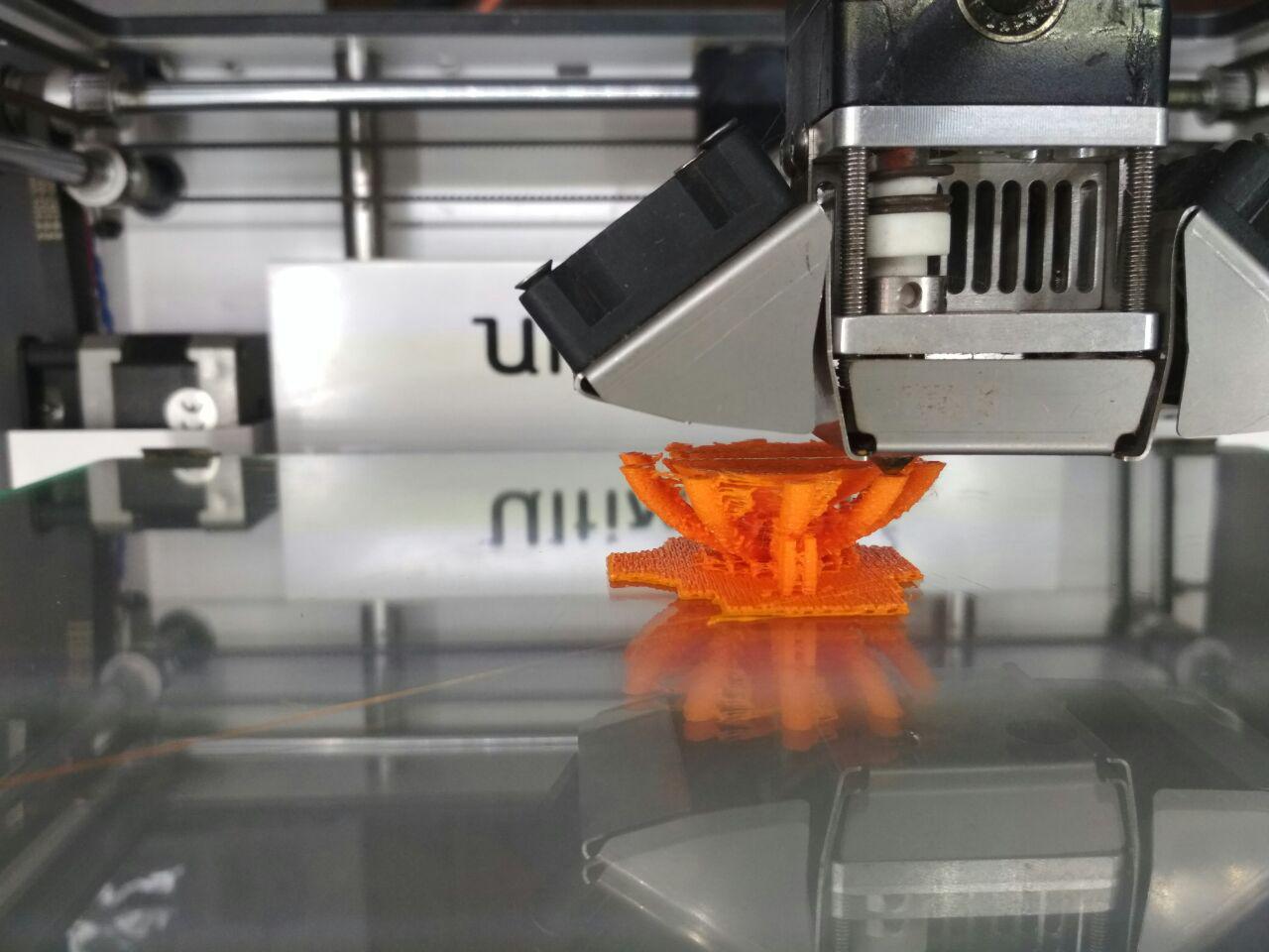
FDM or fused deposition modelling is one of the most common 3D printing process used widely.In FDM mainly we are using a plastic filament, which will be fed to the nozzle,gets heated and extruded through the nozzle to print the model.
We have two 3D printers in our lab,Stratasys Dimensions SST 1200 and Ultimaker 2.
Stratasys Dimension SST 1200
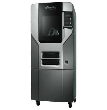
It works under the technology of Fused Deposition Modeling (FDM).Acrylonitrile butadiene styrene(ABS) is the material used in dimension.it has a dual extrutuion nozzle for the support as well as the material.It gives high resolution prints but a drawback is it has strict temperature and humidity controls needed.The finished part is dipped in a chemical filled inside the appartus and boiled after a few hours the support material will be dissolved in the tank and will get the actual part. We have Support cleaning Apparatus SCA1200HT came along with our 3D printer. The input file is in .STL format and catalyst is the software used for dimension.
Ultimaker 2
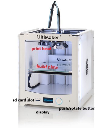
Ultimaker is a family of user freindly 3D printers.They are small and easily portable 3D printers, which is also bsed on FDM,it support printing of ABS and also PLA(polylactic acid).The size of the nozzle is mm and the temperature varies from 180 to 260 degree celcius.Ultimaker also supports .STL format AND cura is the software used here.We are using Ultimaker for our assignment purpose.
CURA
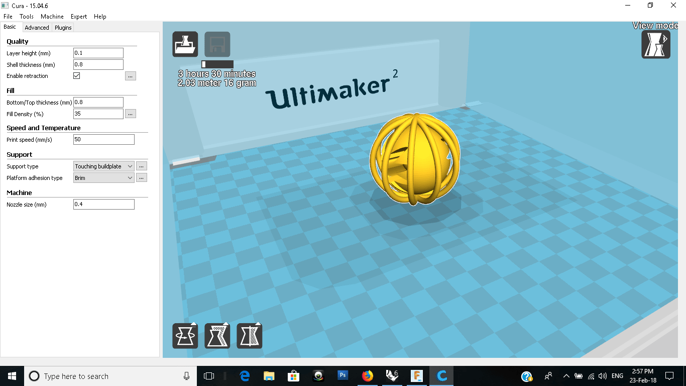
For Ultimaker printer we have to generate the gcode from the .STL files and the gcode is directly given to the printer.Cura is the software which is used to perform the function for Ultimaker.In Cura we import our models,we can scale it rotate it, we can change the layer height,wall thickness,fill density,retraction and choose the support needed for our design.We can see the support in the layer view available.We also get the time and material calculation for our model from this software.After these setting we generate the gcode and is fed to the Ultimaker using a memory card.
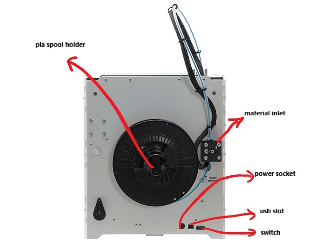
Setting up the machine
In Ultimaker machine setting mainly include setting up the bed ,changing and preheating the material.
For starting with this our instructor gave a factory reset to the present setting.Ultimaker has a guide
of 20-27 steps to guide us with the basic settings.
1)Setting up the bed-Setting the bed is mainly setting the distance between the nozzle tip and the bed surface.
it should be nearly a paper thickness according to our instructor.Ultimaker checks 3 different positions in the bed
and we have to set the bed according to it.
2)Changing and preheating the material -We have to insert the PLA in clockwise direction to the inlet.After inserting few
centimeters the machine automatically pulls the material to the nozzle.Now the nozzle is heated to melt the material,and
when is starts oozing we starts the print.
Trouble shooting
Material clogging - This happened to us in the interval between two successive prints.When the nozzle cools down,the material cloged and covered the nozzle outlet and PLA was not coming out.Now we have to increase the Nozzle temperature,melt the material and remove the clog to resume the printing.In worst cases ,the tube is removed and that much portion is cut out.
Testing the limits of our 3D printer
To know our 3D printer's limitation is important because this will reflect on the actual print quality of our model.
We have downloaded a test print model from thingiverse and is shown below with the test parameters.
model 2
Link to model 1:
Dimensions
01 Nut, Size M4 Nut should fit perfectly
02 Wave, rounded print
05 Holes, Size 3, 4, 5 mm
06 minimal Distance: 0.1, 0.2, 0.3, 0.4, 0.5, 0.6, 0.7 m
07 Z height: 0.1, 0.2, 0.3, 0.4, 0.5, 0.6, 0.7, 0.8, 0.9, 1.0, 1.1 mm
08 Wall Thickness: 0.1, 0.2, 0.3, 0.4, 0.5, 0.6, 0.7 mm
09 Bridge Print: 2, 4, 8, 16 mm
10 Sphere, Rounded Print 4.8mm height
11 Sphere Mix, 7 mm height
12 Pyramide, 7 mm height
13 Overhang: 25, 30, 35, 40, 45, 50, 55, 60, 65, 70°
14 Warp, does it bend?
15 3D Print Font, optimized for 3D printing
16 Surface, Flatness
17 Size, 100 x 100mm x 23.83 (10mm width)
18 Spike, minimum Layer Time, 21 mm height from Bottom (include Baseplate)
19 Hole in Wall, 4 mm diameter, check for proper print
20 Raft Test, raft should be just under the model
21 Retract Travel, check retract settings for longer travel
After printing the results
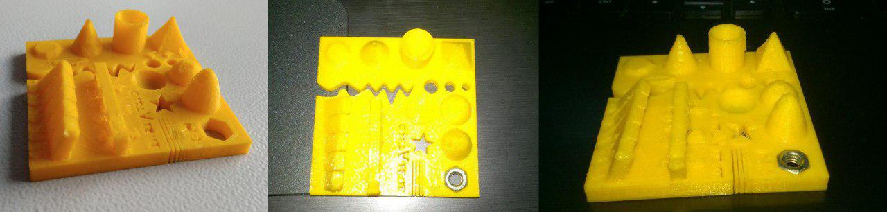
model 1
model 2
After printing the results,Inference-
model 1-the first model was used with layer height 0.1 mm ,
holes were good measuring 2.8 mm,3.71 mm,4.65mm,
the M4 nut is fitting perfectly,
pyramid ,cone has good finishing,
wave and half sphere is visually good ,
walls have some defects,
overhangs came out well and
the bridges were complete apart one side and the fonts were not readble.
so we decided to take one more test print.
model 2-this model also we used layer height 0.1 mm and the only defects noted are wall thickness of 0.1-0.4 mm were missing, the bridges except at 2 mm didn't came out well,
and the overhangs at lesser angle need more support.The rest were present
My Experiment
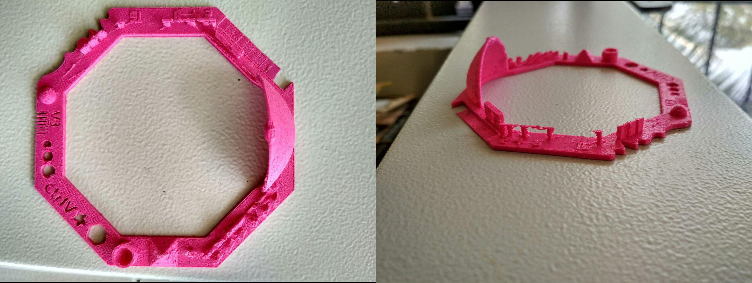
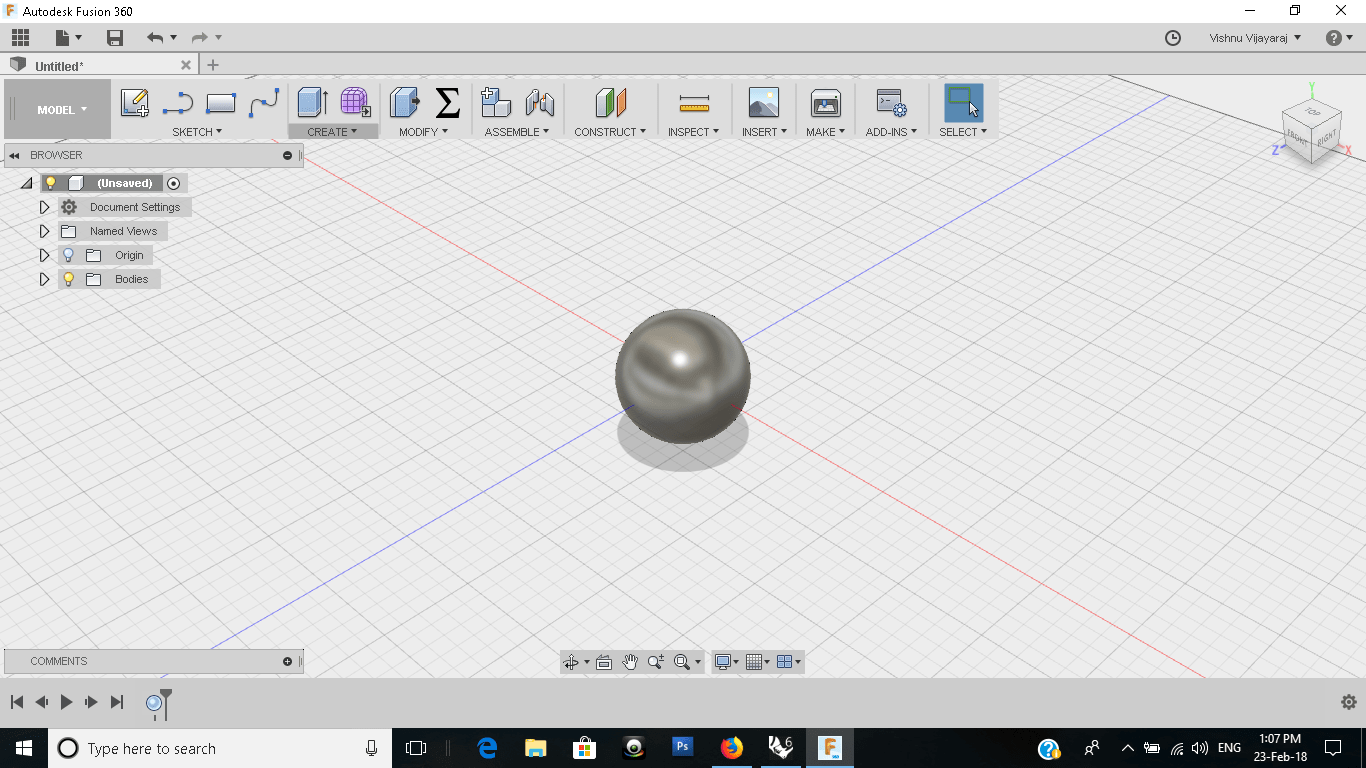
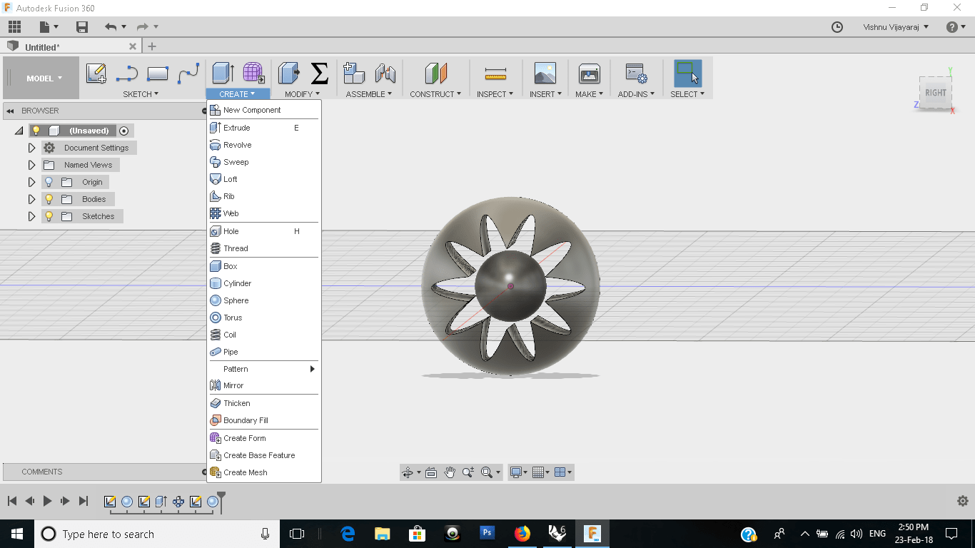
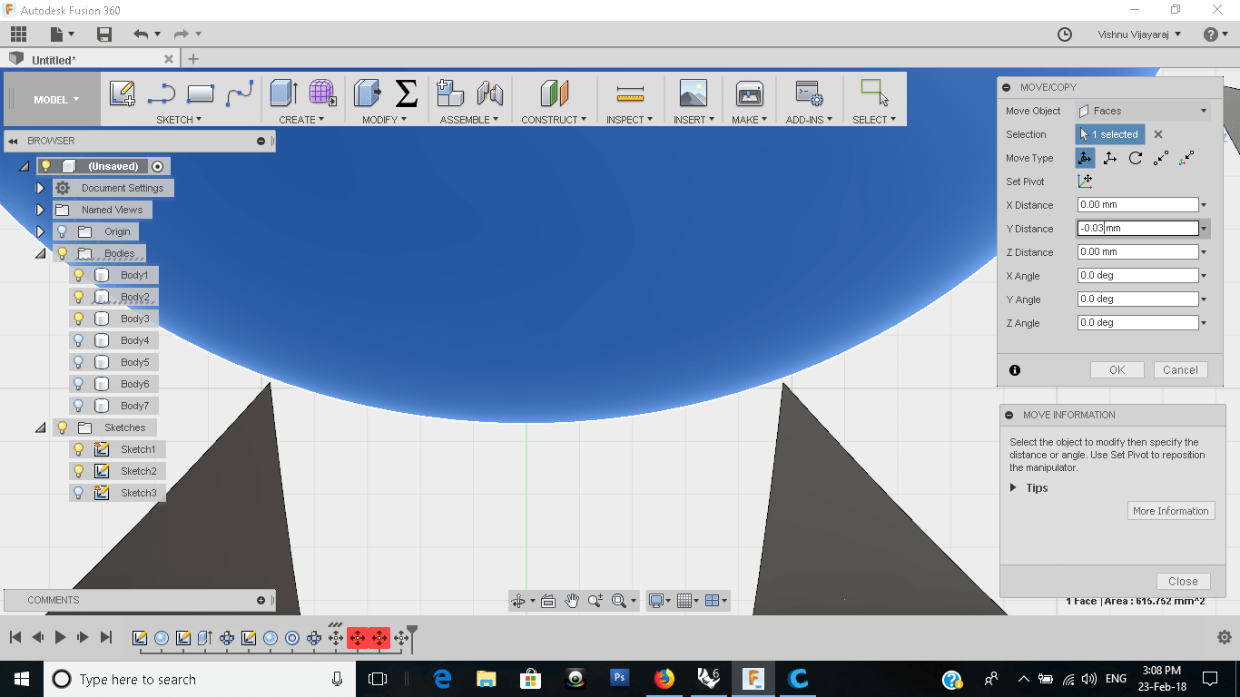
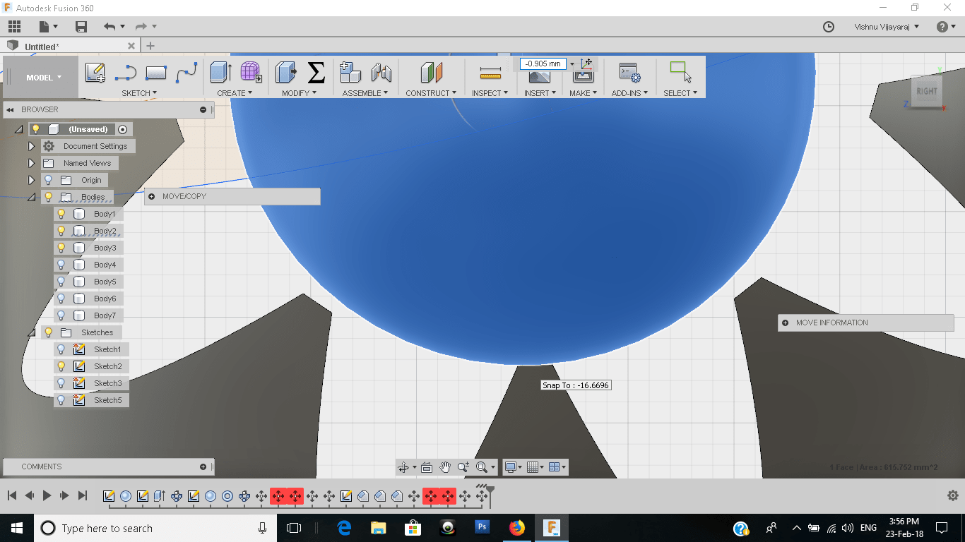
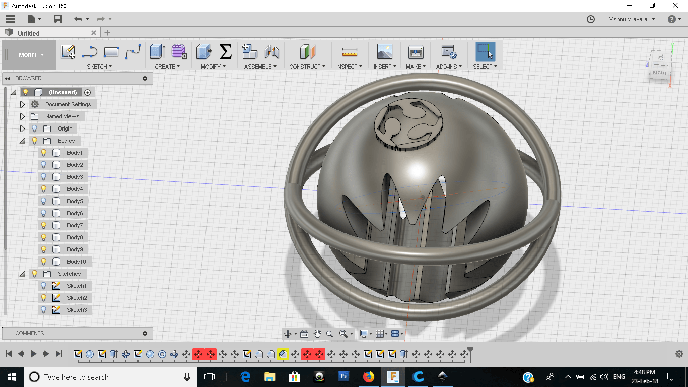
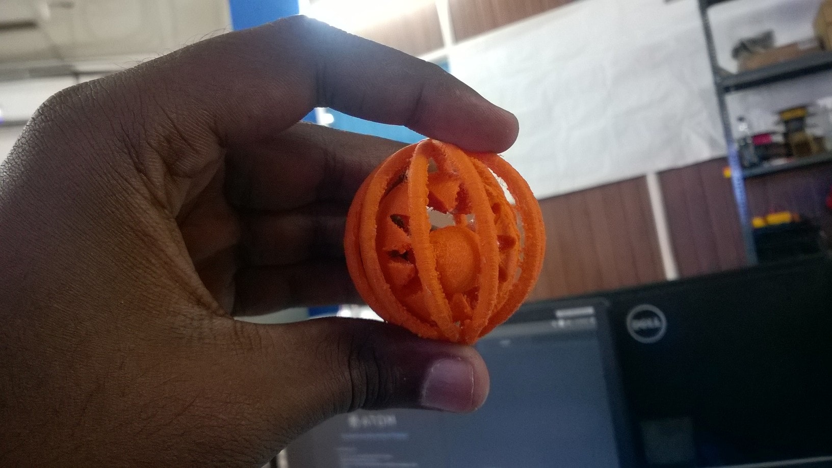
We have to design a model that cannot be made by subtractive process.First I tought of designing a shell but the design complexity made me to choose another.I decided to make a toy for small kids.A small ball inside a sliced sphere enclosed within a cage.Both the ball and sphere is free to move but the ball remains within the sphere always. This creates a ringing sound while shaking the toy.I used Fusion 360 to build my model.
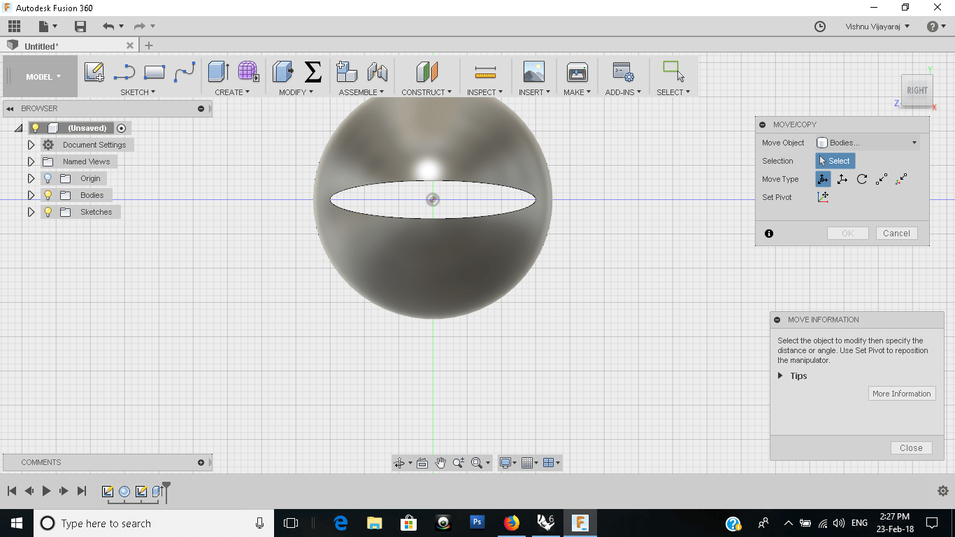
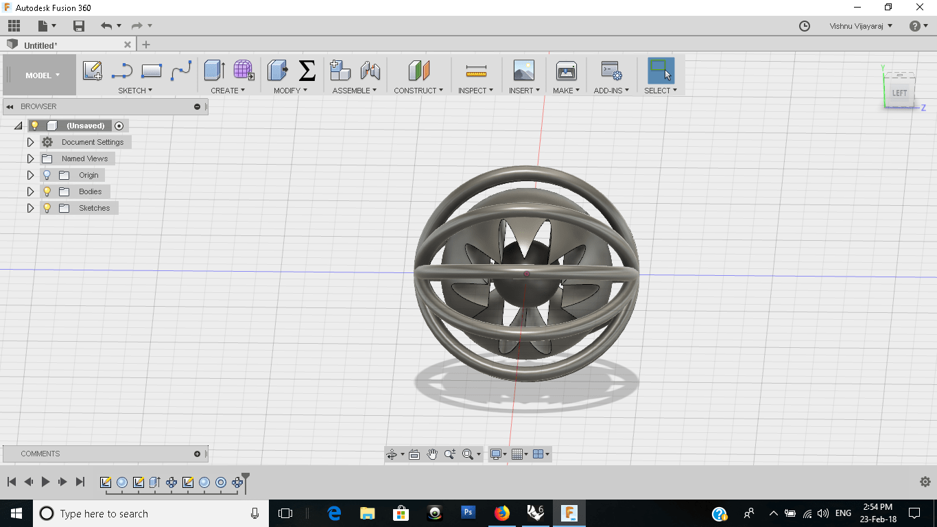
The support for the ball was an issue and for that i chamfered the edges of the cut in the sphere and seated the ball on it.
I also added the fab logo on my model
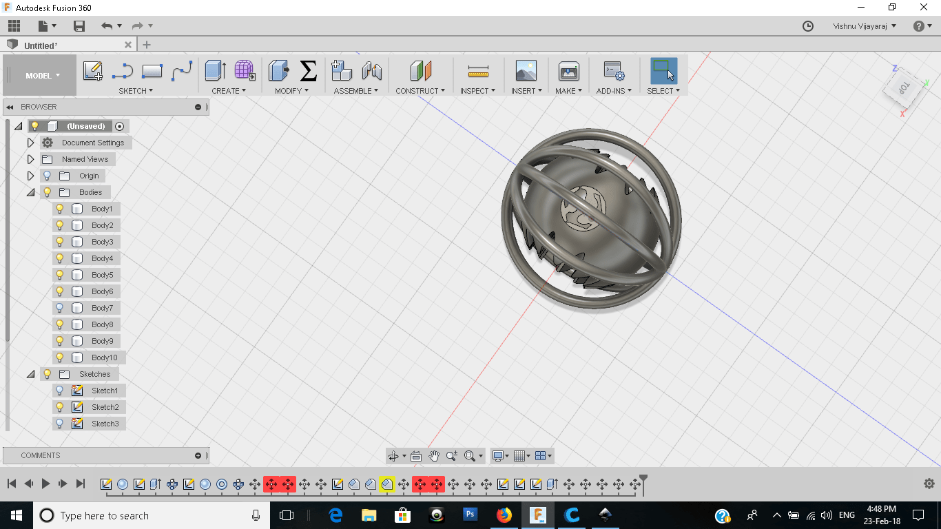
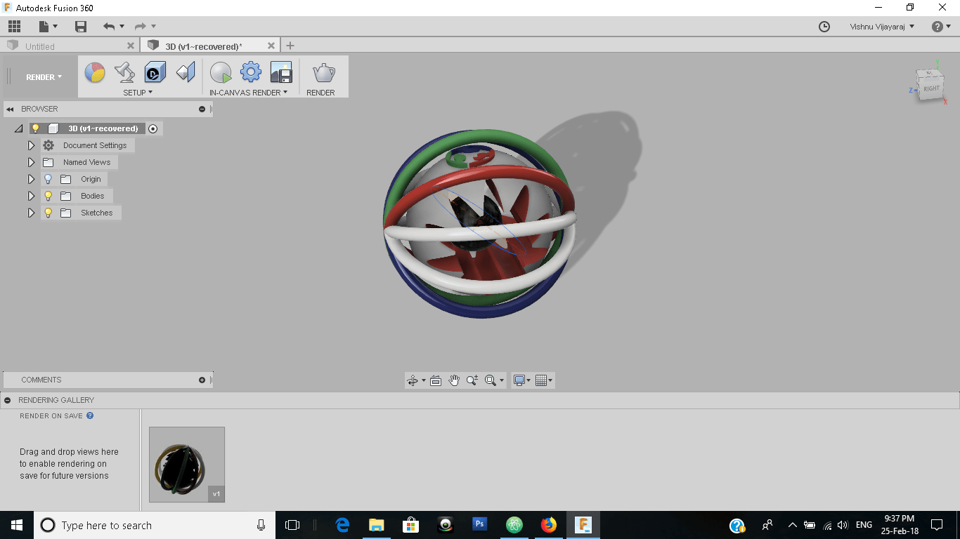
Final rendered view of my model
After designing i installed cura in my laptop and opened the .STL format of the model.I was having confusion with the type of support to be given and my collegue Akhil insisted me to give support everywhere because some parts of my design are likely to fall without support.The next problem was that wheather I can clean the support material if I give support everywhere.For knowing this I printed a low resolution print of my model scaled to half of the original size which took only 20 minutes to complete..
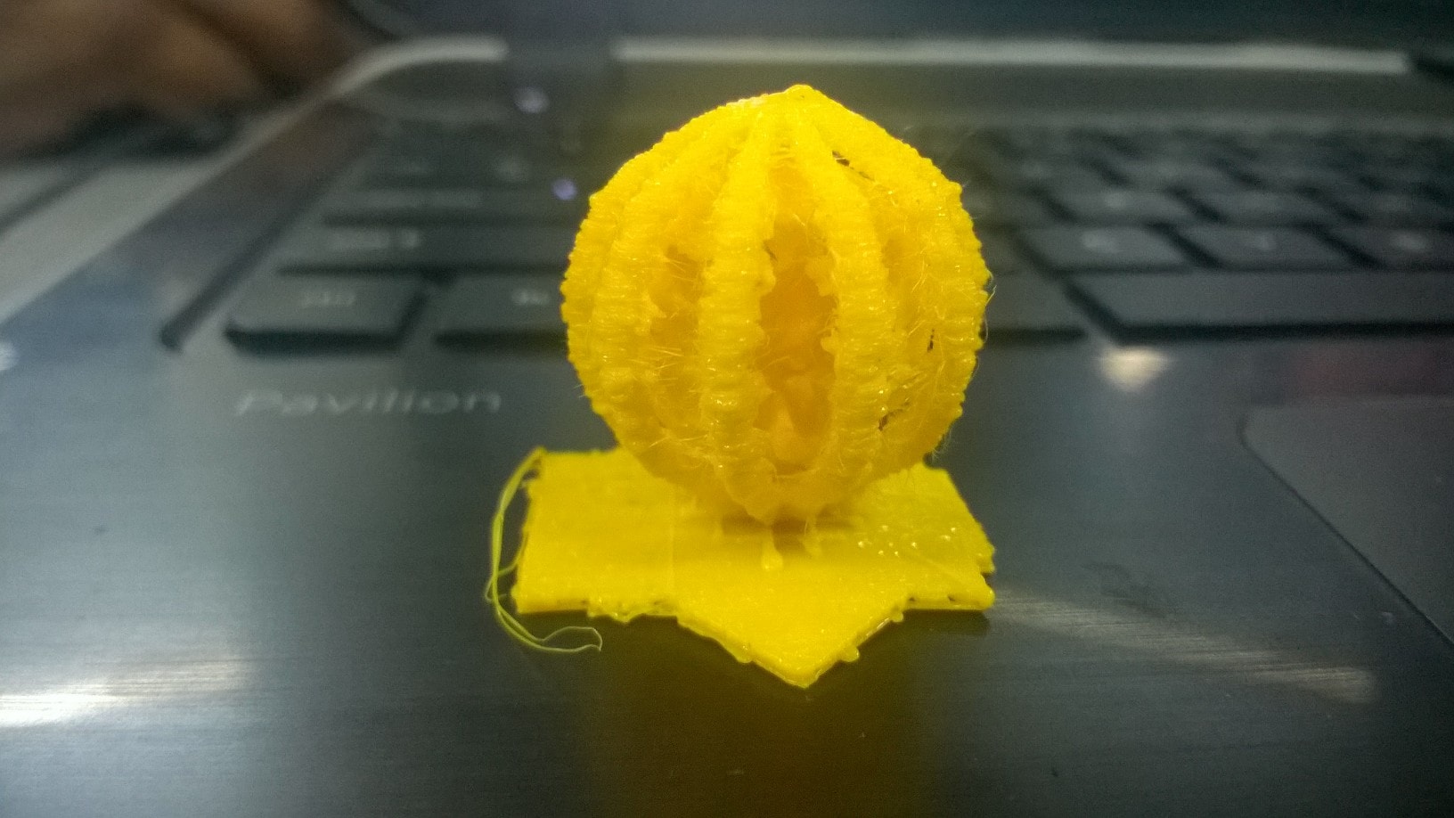
After that I was confident to continue and the building stages are as follows
The final output after removing the support
3D scanning
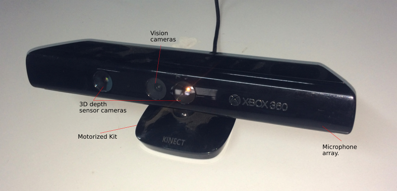
Kinect is a hands-free motion control device by Microsoft for Xbox 360. It allows players to control games using a combination of body movement and spoken commands without having to hold a controller in their hands.The Kinect sensor had a horizontal bar, built into the bar is an RGB camera, a multi-array microphone, and a depth sensor.The depth sensor consists of an infrared projector and a sensor. The projector projects a continuous infrared pattern over its field of vision, which the sensor uses to interpret the scene.
For 3D scanning the first thing we want is to scan ourselves.I too was no different. For this we need a revolving stool so that me and Rinoy removed the back rest of the office chair and made it ready for the 3D scanning.
I first installed the drivers for Kinect and supporting software for scanning.I used skanect and reconstruct me for scanning purpose.
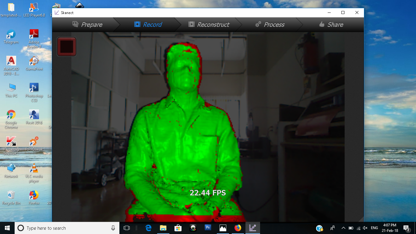
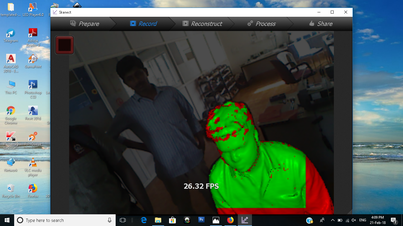
Skanect
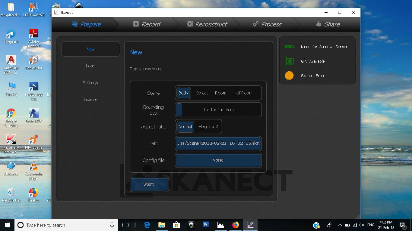
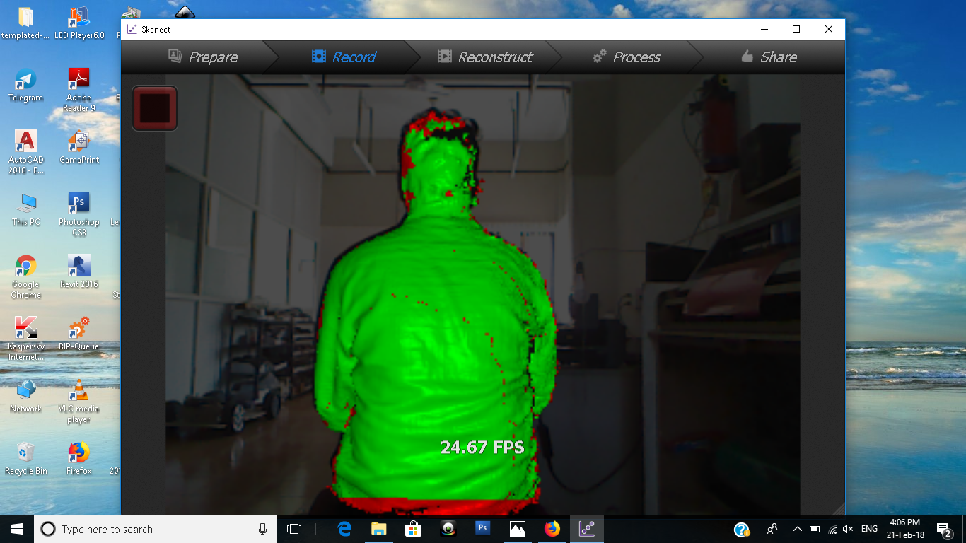
Skanet is an easy software that worked properly and it gives decent scan. The scanning procedure is easy to follow. In the first step you have to set your bounding box and the nature of the item which will be scanned(object,room ,body or halfroom). In the next step place the object in front of the sensor and click record.It will start capturing the 3D data and now rotate the object in 360. The scanned portions will be in green and the rest will be in red. Be careful of moving too fast as it will lose tracking and you will have to go back to the last position where you lost the tracking.
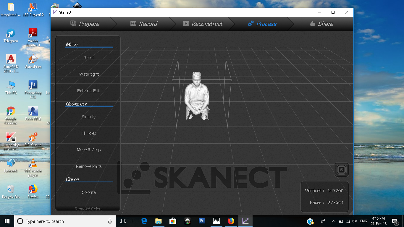
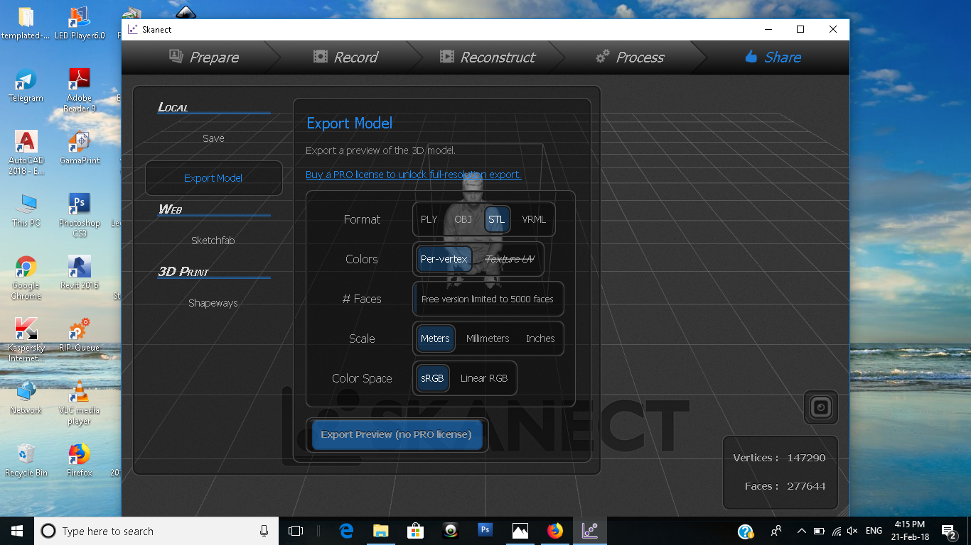
Now in the Reconstruct tab, the software will create the mesh based on the captured data. You can now see the full 3D mesh. In the process tab you can process the data for printing, It will fill holes in the model.
But a main disadvantage in scanect is that we have to purchase it to enjoy fully.We may scan lakhs of faces but our output will have only 5000 faces.I was the first to scan and my out was not good.From next person onward we made sure of the smoothening application to give out a moderate look.
Reconstruct Me
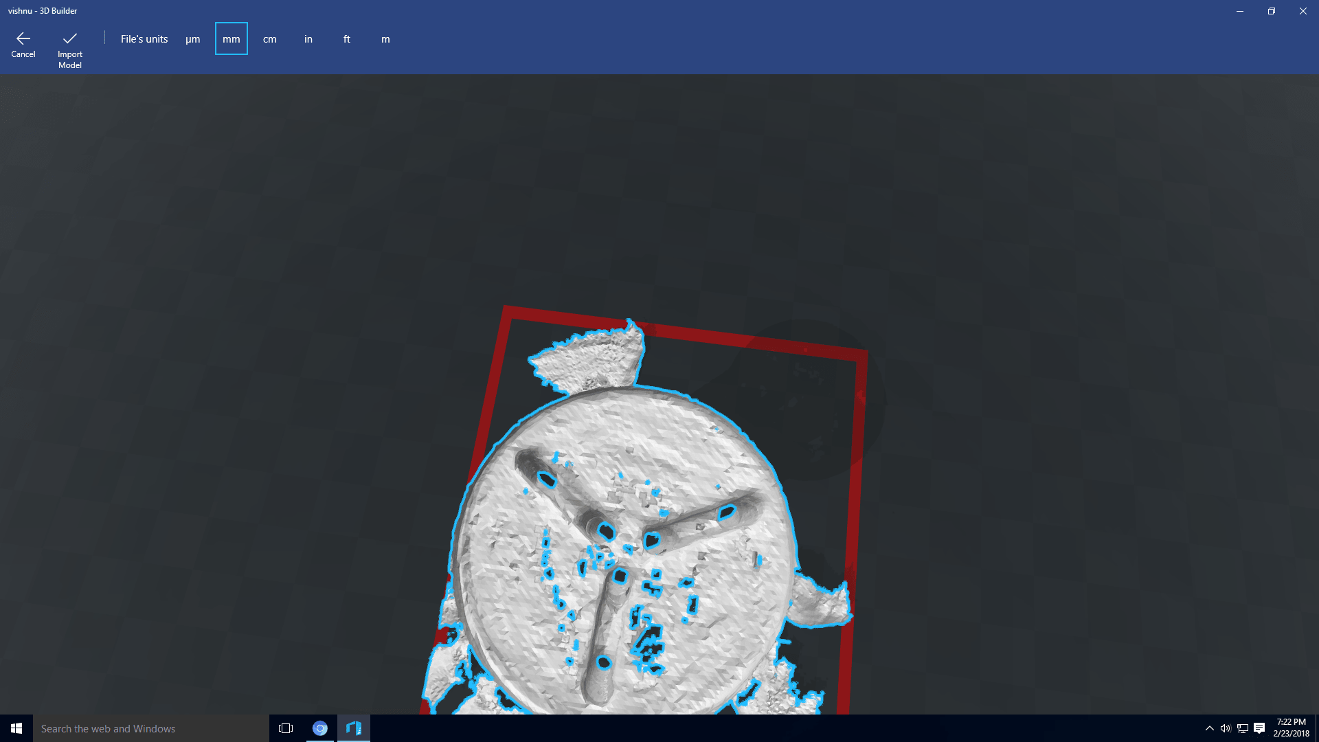
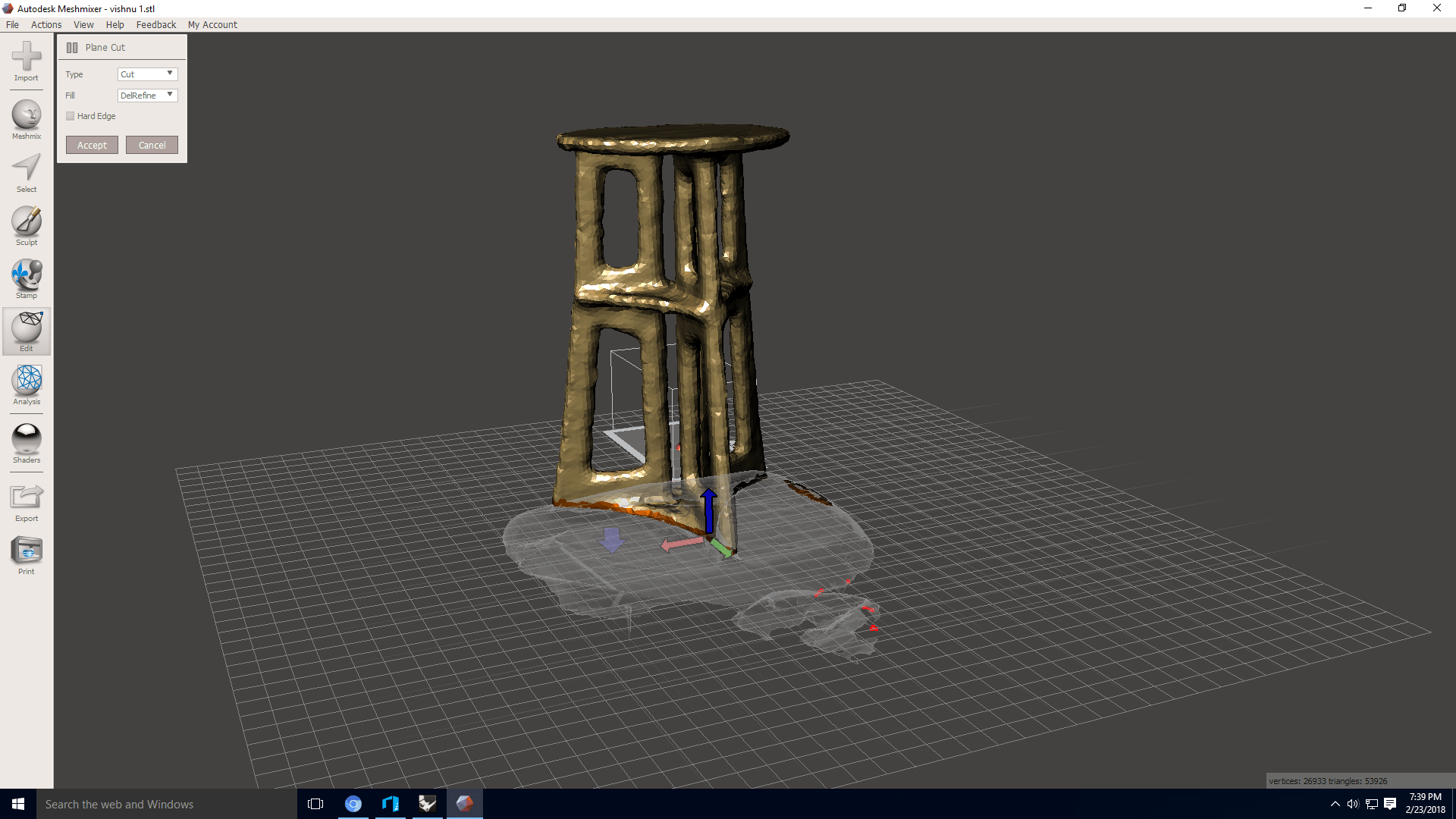
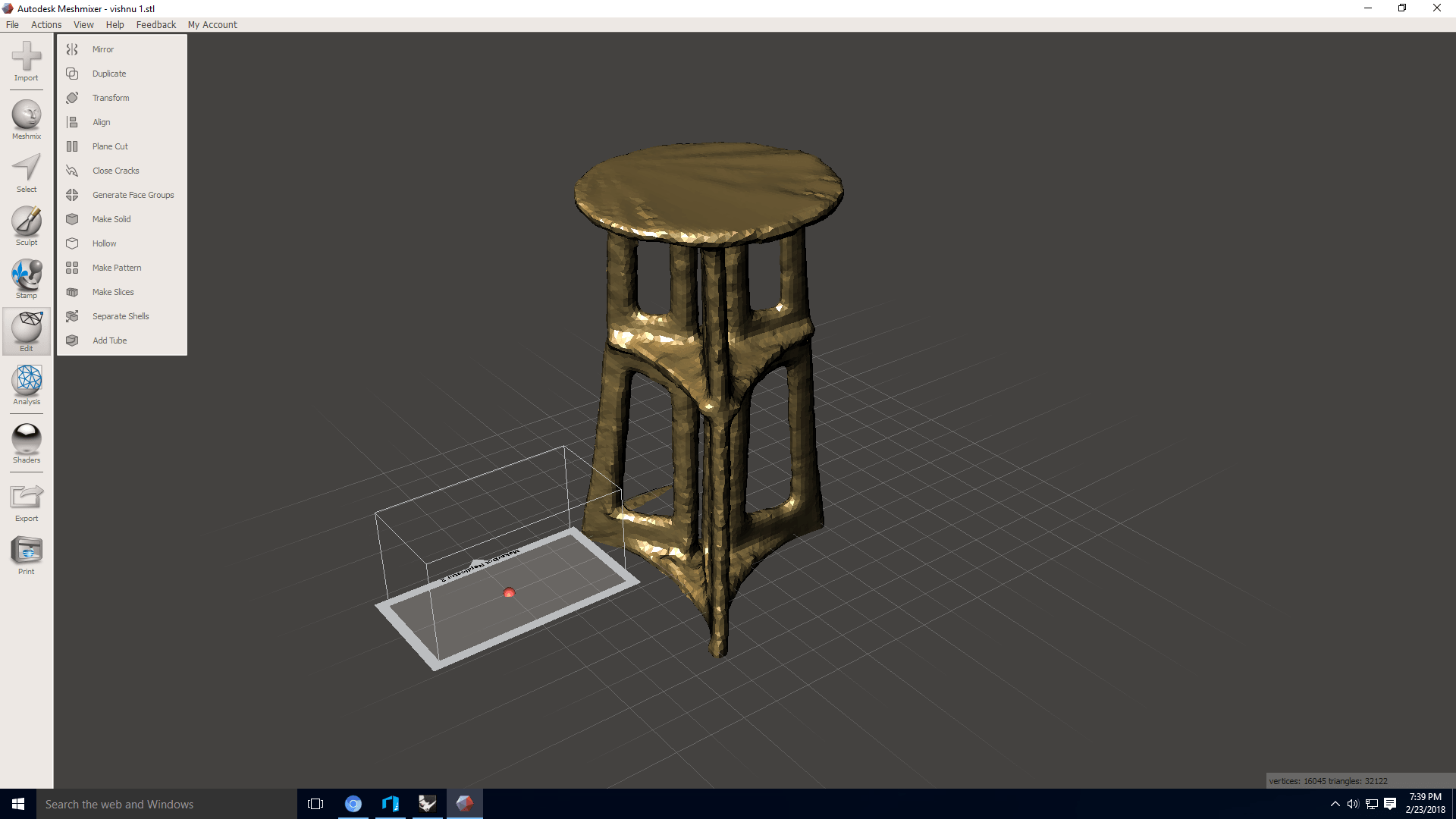
Reconstruct me is a free software available for 3D scanning.This time i decided to scan a stool made of plywood in our Fablab.The main problem of reconstructme is that it loses the tracking more often and from my tries I understood that we have to move the material in a normal pace(not slow)and a bit closer to the sensor than what we had in scanect.
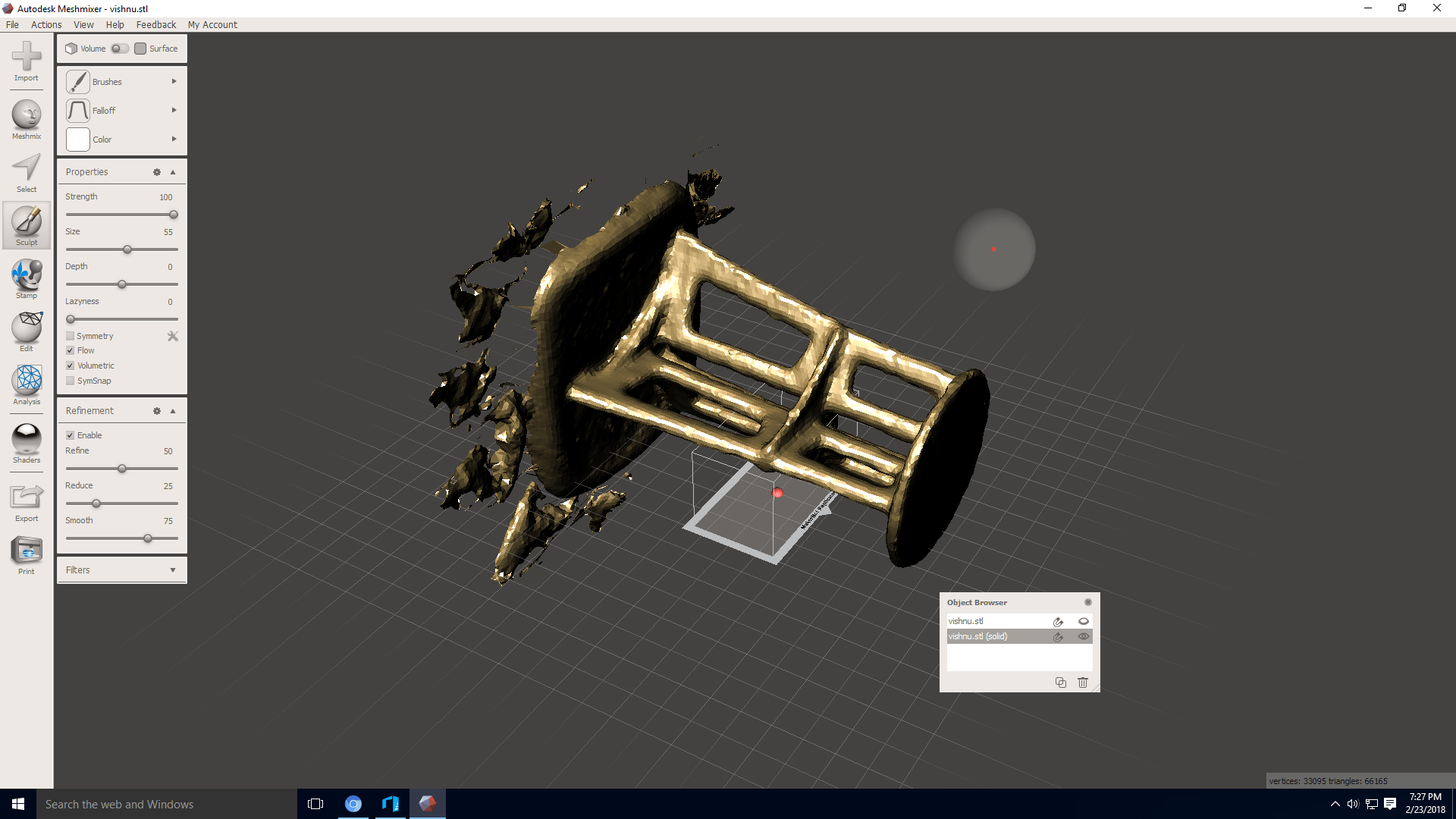
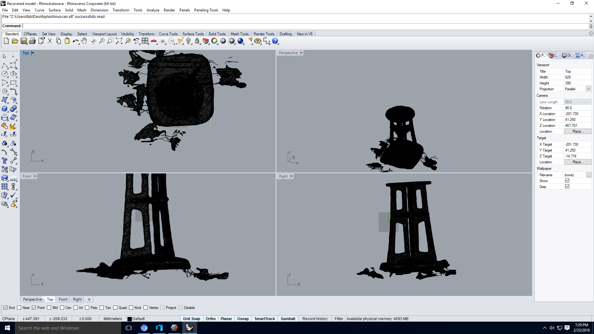
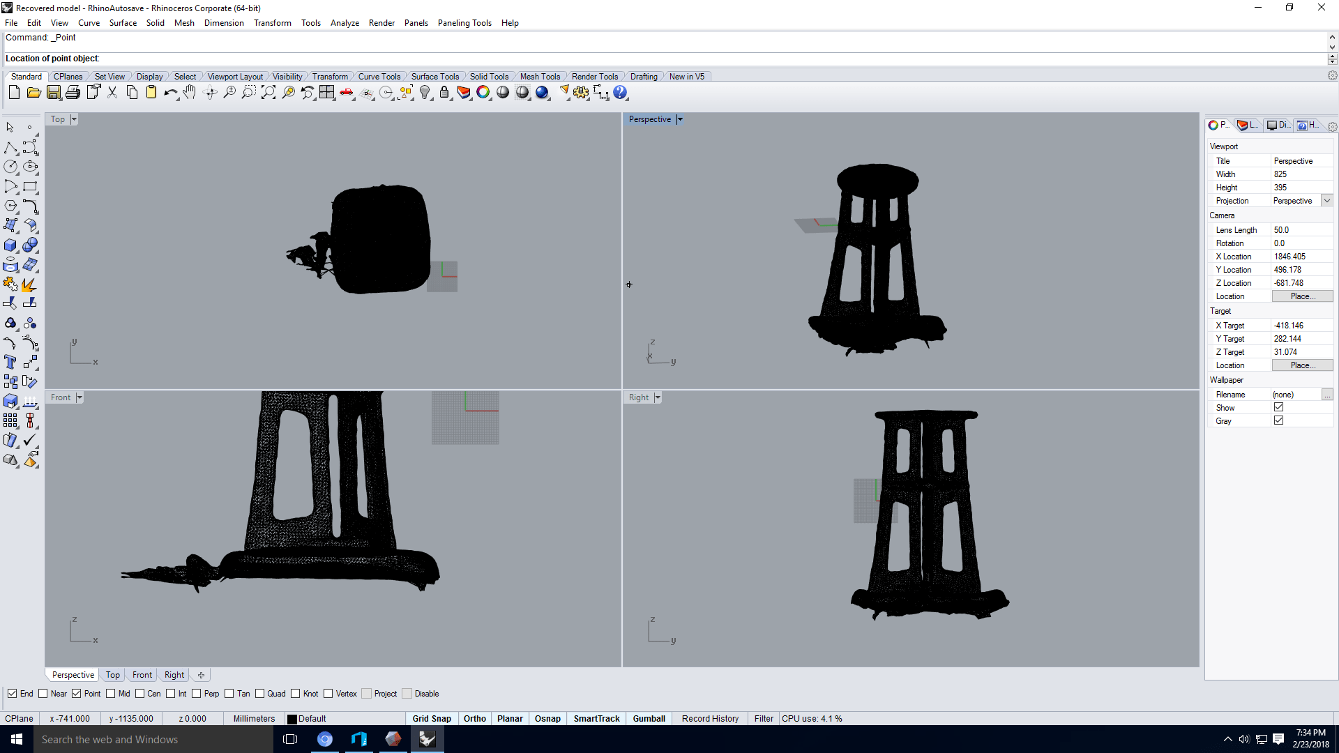
After scanning i used meshmixer to fill the holes and rhino to slice away the unwanted scan portions remaining in the scan.
Summary
3D scanning and printing week was an enjoyable week.I am very glad to get introduced and having hands-on with the
3D printers.It was fun tweaking office chair at our lab to set platform for 3d scanning.At the last day of the week we got an oppurtunity
to use dimension(3d printer at our lab) which was under some maintenance issue to work with.In that machine we printed the test print as well
as a dice designed by me in the 3D designing week.