This week the assignment is to write an application that interfaces with an input or output device.The whole thing is
new to me and the troubleshooting efforts of my output week have already delayed me,So I am planning to start with a simple project.I plan to
control the leds in my board using a HC-05 bluetooth module using MIT app inventor.
HC-05 bluetooth module
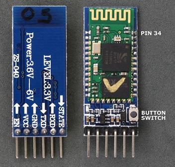
HC-05 bluetooth module
HC-05 is a bluetooth module which is a MASTER/SLAVE one used for the communication between two microcontrollers
or communicate with any device with bluetooth functionality i.e.,phone or laptop.This module is basically used for transfering simple datas,but cannot
be used for transferring multimediia files like photos or songs for which we will have to seek the help of other modules.This bluetooth
module communicates with the microcontroller using RX and TX pins via serial communication.
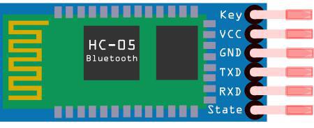
There are six pinouts from the module of which we will be using 4. Mainly VCC, GND, TX, RX.Always make sure that the TX of the module is connected to the
Rx of the microcontroller board and vise versa.While pairing the default password for the module is 1234
You can read more about HC-05 bluetooth module and acess its datasheet
MIT APP INVENTOR

MIT App Inventor is an opensource online programming environment that allows us to build a fully functional
apps for smartphones and tablets.This application is very good for beginners and user friendly.Basic tutorials are available for MIT App Inventor or we can find some in the youtube as well.It has
basically two windows:
1)Designer:Deigner window is where we design the basic page of our app.We have tools like buttons,listpicker etc where we can design
the basic look of our apps.This window is mainly like visual designing of our app
2)Block:Block window is where coding happens.The speciality of this platform is the block based coding which makes it more user-friendly.
Anyone can easily learn this within a few hours.
WORKFLOW IN MIT APP INVENTOR
1).So to use this first we have to register with our mail id in the app inventor site.
2).Now we have to start a new project.After this we will be directed to the designer window.
3).In the designer window we use interfaces like buttons ,label etc and tools like text ,xolour,image to
design the app.Also do not forget to add the type of connecctivity from the tab on the left side.
4).Now we have to go to the block section,where we do the coding in means of blocks.In the block editor the
interfaces we added in the designer part can be coonnected to perform various tasks,where various task pallets
are available for each.From that we have to choose.There are also logical block like not,true etc which can be
added and used accordingly.
5).After finishing these steps we can either download the .apk file or generate barcode from the build menu for accessing the app using
our smartphone or laptop.
APP DESIGNING
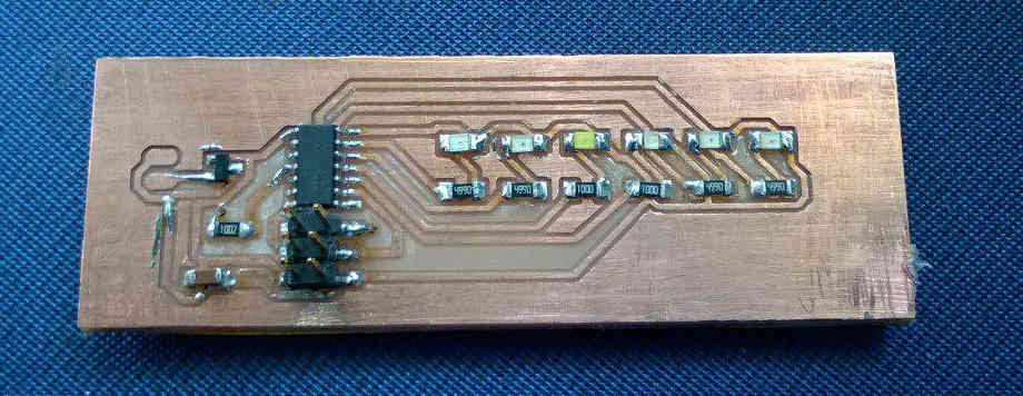
So I am designing this APP to control the led in my board I have designed for my input week.The board contains two leds , one red and one orange.
below shown is the image if the input week board.
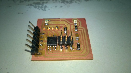
input week board
The screenshot off mit app inventor are shown below:

After designing the APP I downloaded the apk in mobile and connected it to the bluetooth module.Eventhough the bluetooth is getting connected I
was not able to control the led.
Trouble shooting
One whole day I sat along with my board troubleshooting to find the problem and solve it but all my effort ended up in vain.I was already late for the week and in the chaos I didnt take any photos of my troubleshooting process but i will list my steps down here.
The different troubleshooting I did are:
1).Since I send data in char format I changed the integer numbers to characters and tried-unsuccessfull
2).From last year student,Rahuls page I found out that he has send data as strings,according to him one byte data while in transmission is likely to get lost so he has tried string and I too did the same -unsuccessfull
Now I realised that the problem was not with my app as every time data is getting send when I press the button on my phone and the led in the bluetooth module is indicating it,so the data is getting received and now I started to concentrate on my board.
3).I tried to blink the both leds with a normal code and they were perfect.
4).I tried to print using the serial monitor and I am getting result in different baud rate.same problem i faced in input week(abscence of external clock)
So my conclusion for the board for not working are:
1)abscence of external clock making serial communication at different baud rate.
2)I used ATtiny 45 in this board and i havent given proper pins for Rx and Tx.The Rx pin was assigned to SCK pin which I suspect is the main issue for all these).
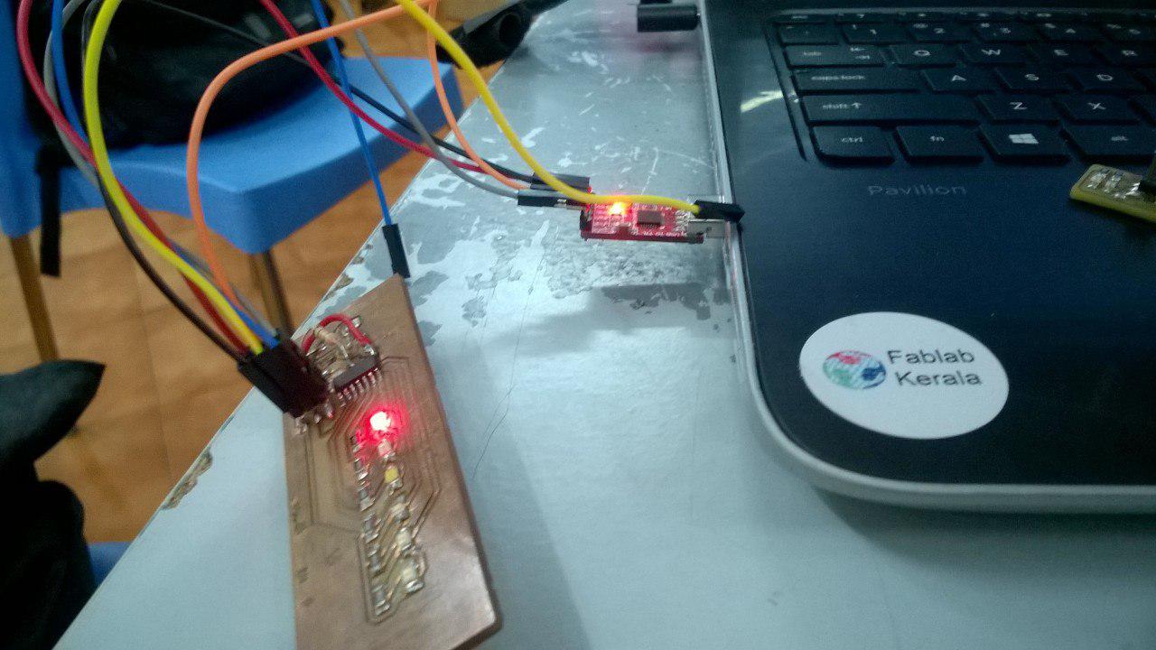
So the only option left with me is to use my output week board.The image is shown below:
output week board
This board was made for the purpose so there was no FTDI cable connector in it.So what I did was I removed the voltage regulator I used for connecting battery and in that trace FOr VCC and GND I soldered a single pin header for powering the board.So that the 6 pin header could be used for connecting the bluetooth and communication purpose. the image of the board after the moderations are shown below:
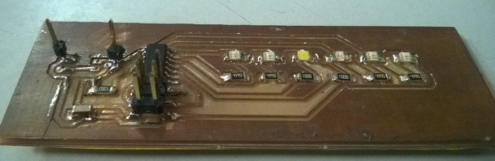
output week board after the modification
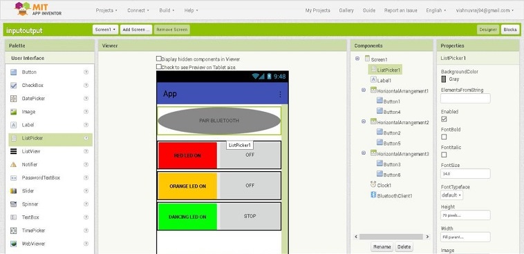
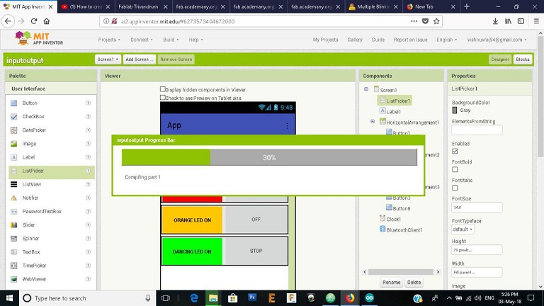
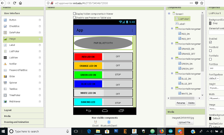
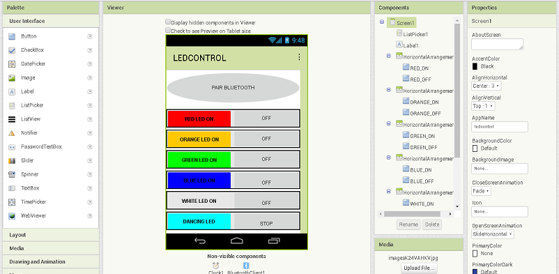
RE-DESIGNING the APP
As the board contains more leds I have to redesign the app according to it and the screenshots are shown below:
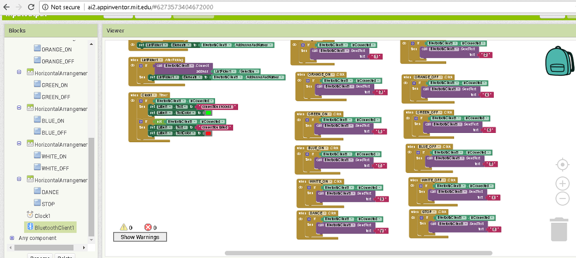
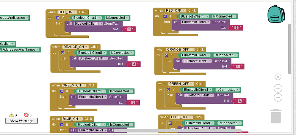
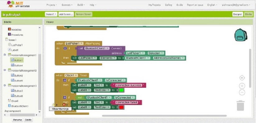
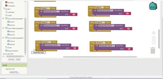
CODING FOR THE APP
As I have written the code earlier I just have to include the additional leds control and change the control pins.The code is shown below:
The code is written in such a way that there is an ON and OFF switch for each colour leds(for orange there are two leds controled by a single switch).
DANCING LED is just a small blinking program I have written to control the leds.
STOP switch is like a universal switch to off all the leds.
Working of the APP
Below shown is the video showing the working of the app.
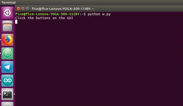
PYTHON-TKINTER

So after finishing my assignment with APP INVENTOR during the time of global Evaluation my Evaluator suggested me to
try some other type of programming and hence I choose Python-Tkinter.Python is an interpreted high-level programming language for general-purpose programming.
Tkinter is Python's standard GUI (Graphical User Interface) package which is widely used.According to Wiki ,Tkinter is a Python
binding to the Tk GUI toolkit. It is the standard Python interface to the Tk GUI toolkit,and is Python's de facto standard GUI.
Below mentioned are few links to Python-Tkinter Tutorial:
I have mainly used the first tutorial for doing my programming.So in python we need to import some libraries mainly to work with.Eventhough I have python installed
in my windows laptop it is not working and showing serial import library error,I borrowed my friend Amiths Touchscreen laptop(which he told me to mention attribution) for this assignment.
Interfacing my output board with leds
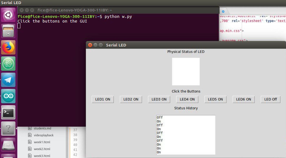
I am planning to do the same program I did for the MIT APPInventor and create a GUI with python programming providing buttons for each led and a universal off button.
So my intention is simple,i.e., to try as many tools as possible.So I wrote the code in python to create the GUI.I named it as SERIAL LED
given below is the code:
In arduino I have nothing much to change just some changes to my early written code:
The code is given below:
So after burning the code the real problem began.The board is not working.I thought it is because of the modification I did early for this board and tried to take out the glue I poured to the single VCC and GND pins,
and while doing so some traces were also torn off.Now I put jumper wires and added Through hole type pull up resistor for reset as the trace where torn off.Now checked thw board with led lighting program and the board is working.
Again I checked with the GUI but theboard is not working.I tried using serial monitor and for a baud rate 9600 it is getting communicated at the rate of 38400 or something at that range.I changed it in the code
for python and tried and again the attempt failed.
serial communicating at different baud rate
Now the only option is to doubt my arduino.YES IT IS.This gave me the answer for the doubts I had using my INPUT board this week.I burned the code on Amiths Laptop,in the arduino version it had and it completely worked.
The working video is attatched below: