The inspiraton
In Fab Academy schedule apart from the weekly assignments we have to do a project using the skills we have learnt here.For the project I am
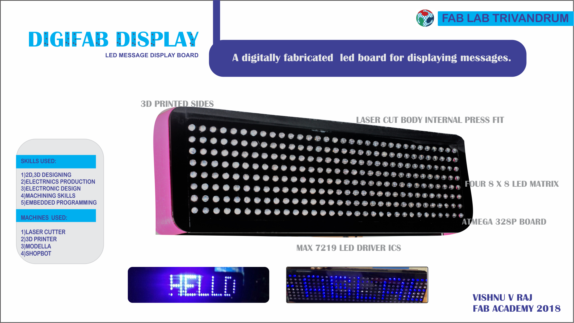
sticking onto with my initial idea of doing an LED message display which I would like to call as DIGIFAB DISPLAY .In this page you can see my growth over my
Final project from the initial weeks.
PROJECT IDEA-DIGIFAB DISPLAY(A lookback to my first week)
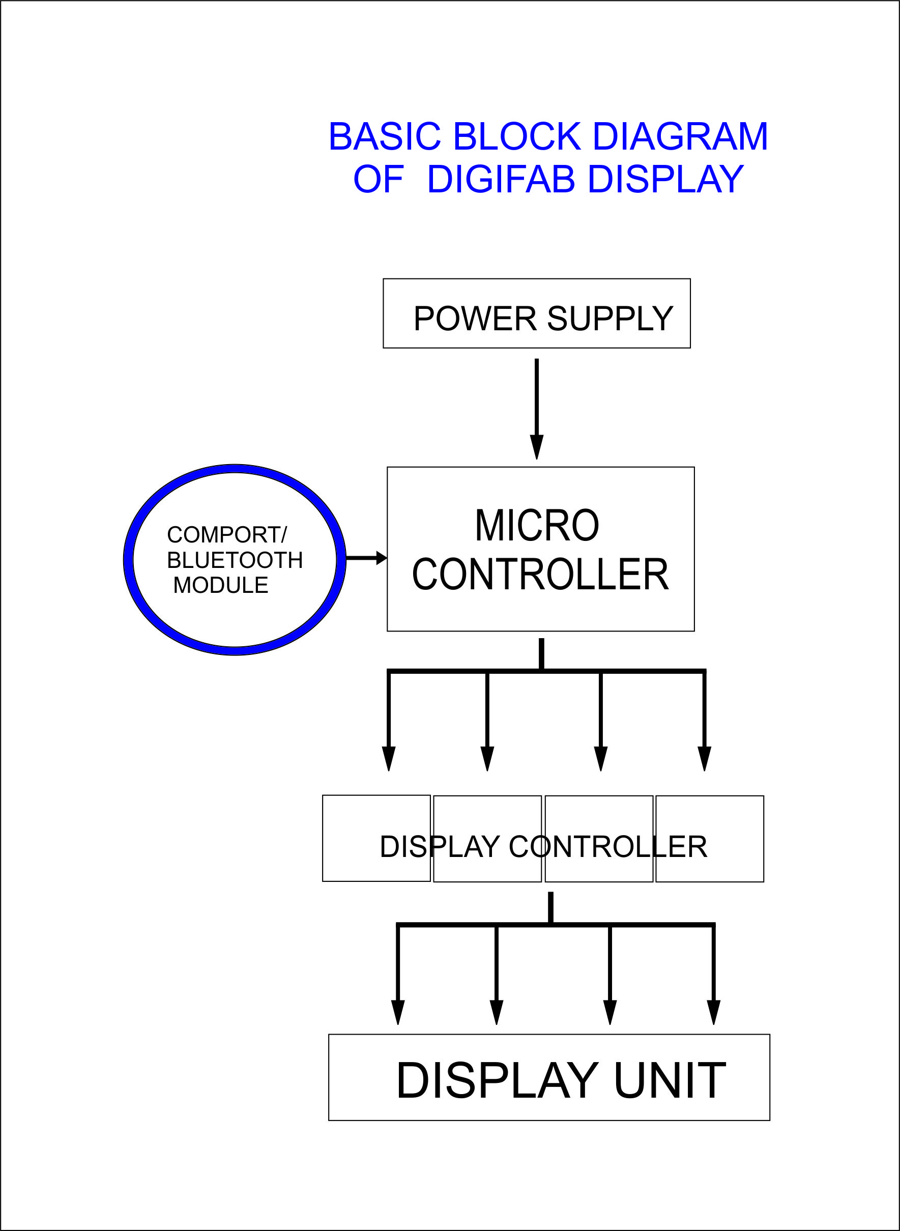
DIGIFAB DISPLAY will be name of my project work meaning a digitally fabricated banner box with digital display.
A matrix of led's i.e.,arranged in rows and coloumns which displays a message from an input either a comport or a bluetooth module in a scrolling motion.
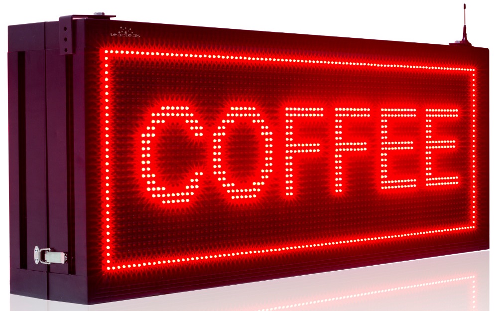
This is a commercially successful product seen at every corner of my city.I often wondered how these works and decided to do it as my
Final project.
While choosing this project I dont know anything about electronic connections,soldering ,milling.Only what I know that I will have to solder down
256 leds.I watched few videos in instructables of which many of them where using shift registors to shift the message or text.By that time my instructor told me about Led
driver IC's can also be used.He told me to refer about it.
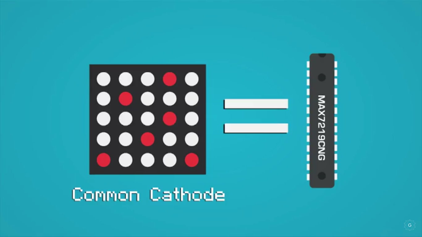
THE LED DRIVER IC -MAX7219
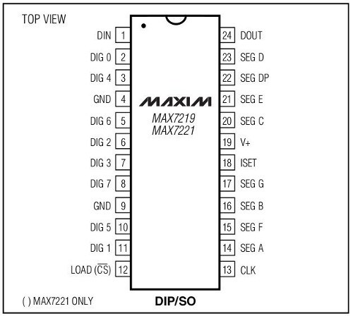
I found out that maxim integrated has Serially Interfaced, 8-Digit, LED Display Driver IC's named Max7219 and I read its datasheet.Max 7219
and Max7221 are similar IC's and share a common datasheet.[From the datasheet]The MAX7219/MAX7221 are compact, serial input/output common-cathode display drivers
that interface microprocessors to 7-segment numeric LED displays of up to 8 digits, bar-graph displays, or 64 individual LEDs. Included on-chip are a BCD code-B decoder,
multiplex scan circuitry, segment and digit drivers, and an 8x8 static RAM that stores each digit. Only one external resistor is required to set the segment current for all LEDs.
These is compatible with SPI, QSPI, and MICROWIRE communication.
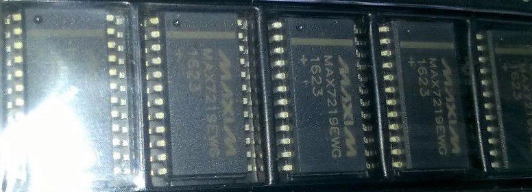
So after reading the datasheet I choosed MAX7219EWG as it has an operating temperature much higher than the other variants.I
bought 10IC/lot from aliexpress website.For the link go
Talk with NEIL (Electronics Production Review)
So during the Electronics Production review,the random generator picked me for the review,the first one from my lab during this academy.He
asked my Final project plan and on hearing about the DigiFab display,He told me it is a nice project and gave a reference of
and told me to keep this as a bar and go with something higher than this.I must say he had done a fabuolous job
and admire his work.
I am glad that I had a chance to talk with Neil at the early stage itself so that It was really helpful for me to work with my project.After this talk with Neil,I began to
search for the limits that I could go with this project
Choosing LED's
One of my instructor has done a audio spectrum analyser for his project
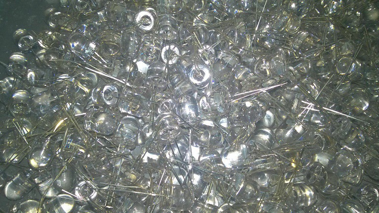
with 100 Leds and that where 2mm x 5mm rectangular leds.I noticed that was not enough I decided to go with 8mm leds but my instructor VinodKumar BG told me that try 10 mm leds instead of 8mm,it would give a rich view.So I ordered 10 mm blue
Led's from ebay.
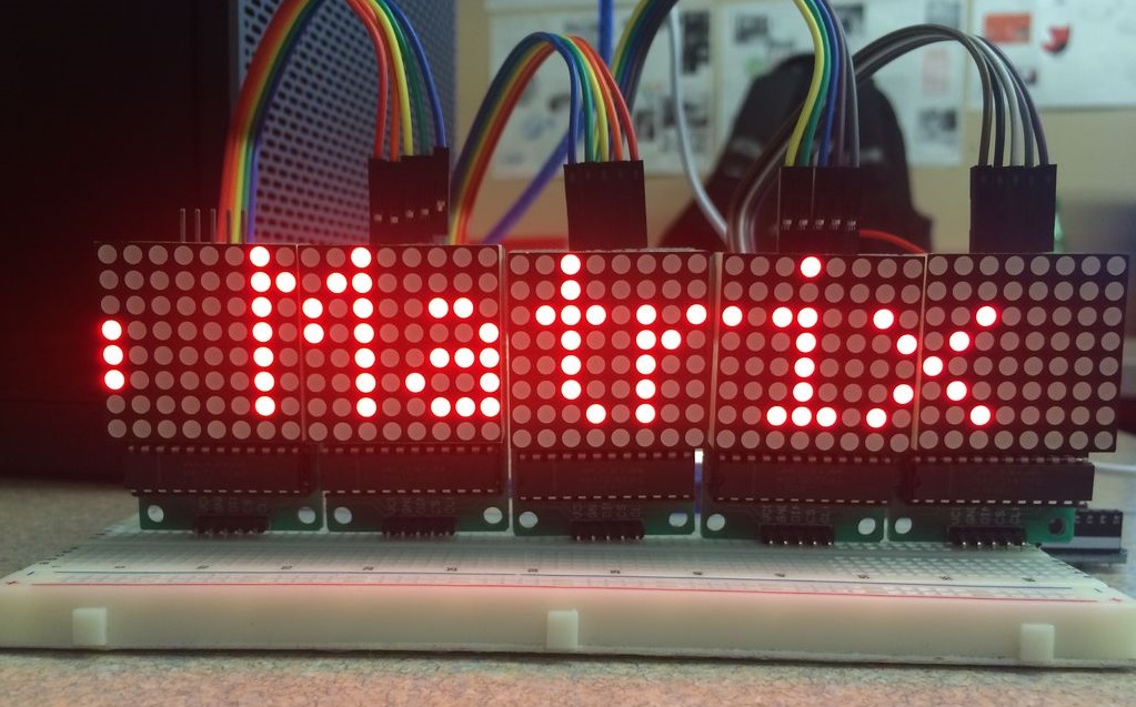
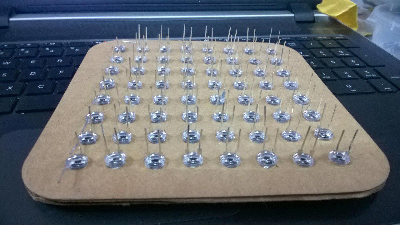
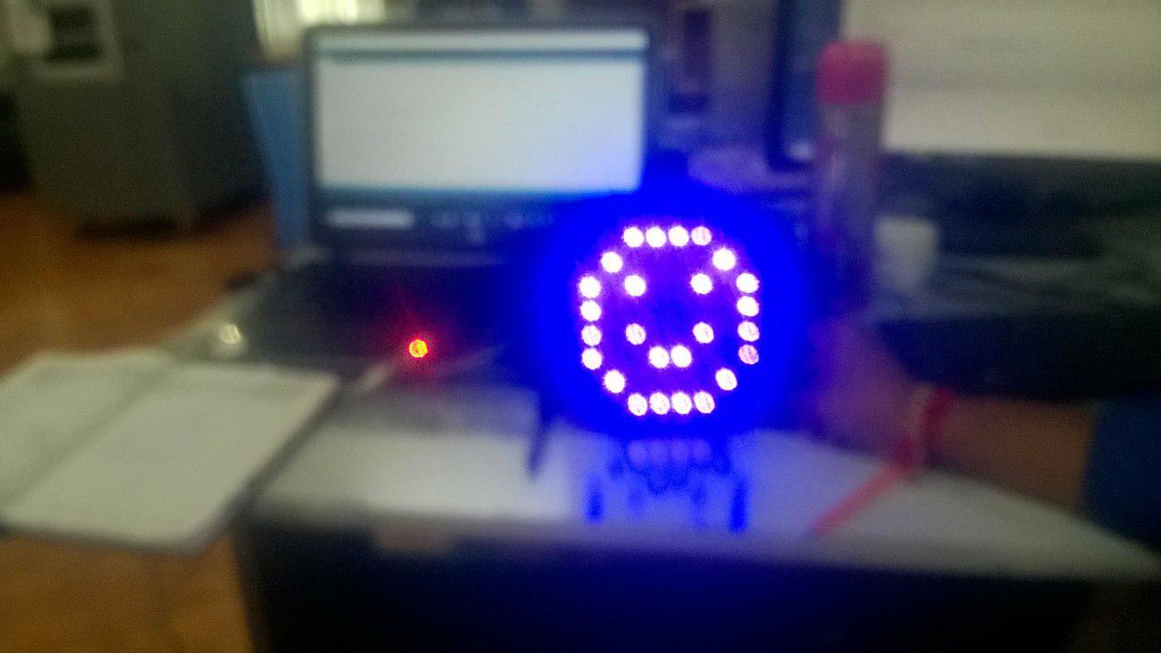
MAKING A TEST MATRIX DISPLAY
Before going on with the production I wanted to make a test 8 X 8 matrix so that I can check the working of the IC ,code etc.I did a base with cardboard,cut the holes in the laser cutter
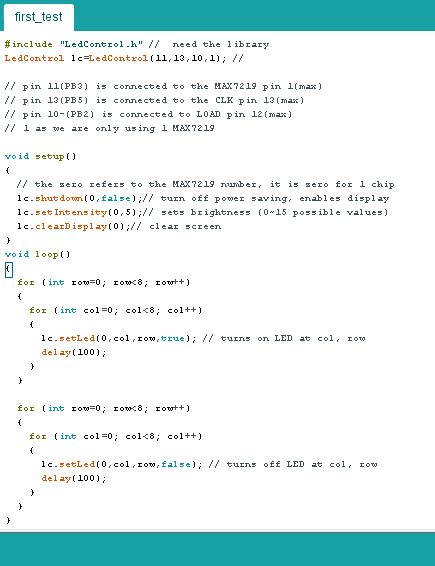
for 8 mm leds(I have purchased 70 leds inorder to test this from local market).After inserting the leds each LEDs were tested and connected with the MAx IC board I milled using eagle software.
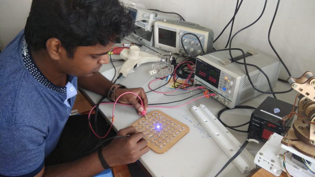

I traced the board on eagle and gave the connections.I used an arduino nano for controller the display driver.The wiring was not perfect I guess as It didnt worked for the first time.At first when I ran
the code all LED's blinked for some time with a delay.I was literally crying and searched the internet the whole night and found that if the connection was not proper all the leds will blink.


The next day I rechecked the connections and found some overlapping connections with the wire connected to the board,removed them and connected,and it worked fine.I tried some random code from Instructables and was very happy.
So from this test cut the conclusions I made was that the wiring it difficult so I will have to manually route the max IC board in arrangement so that the cathode and anode connections are in a single line.It will be easy for me while
connecting and also no wires will be left tangled.
Testing the Single LED matrix-results
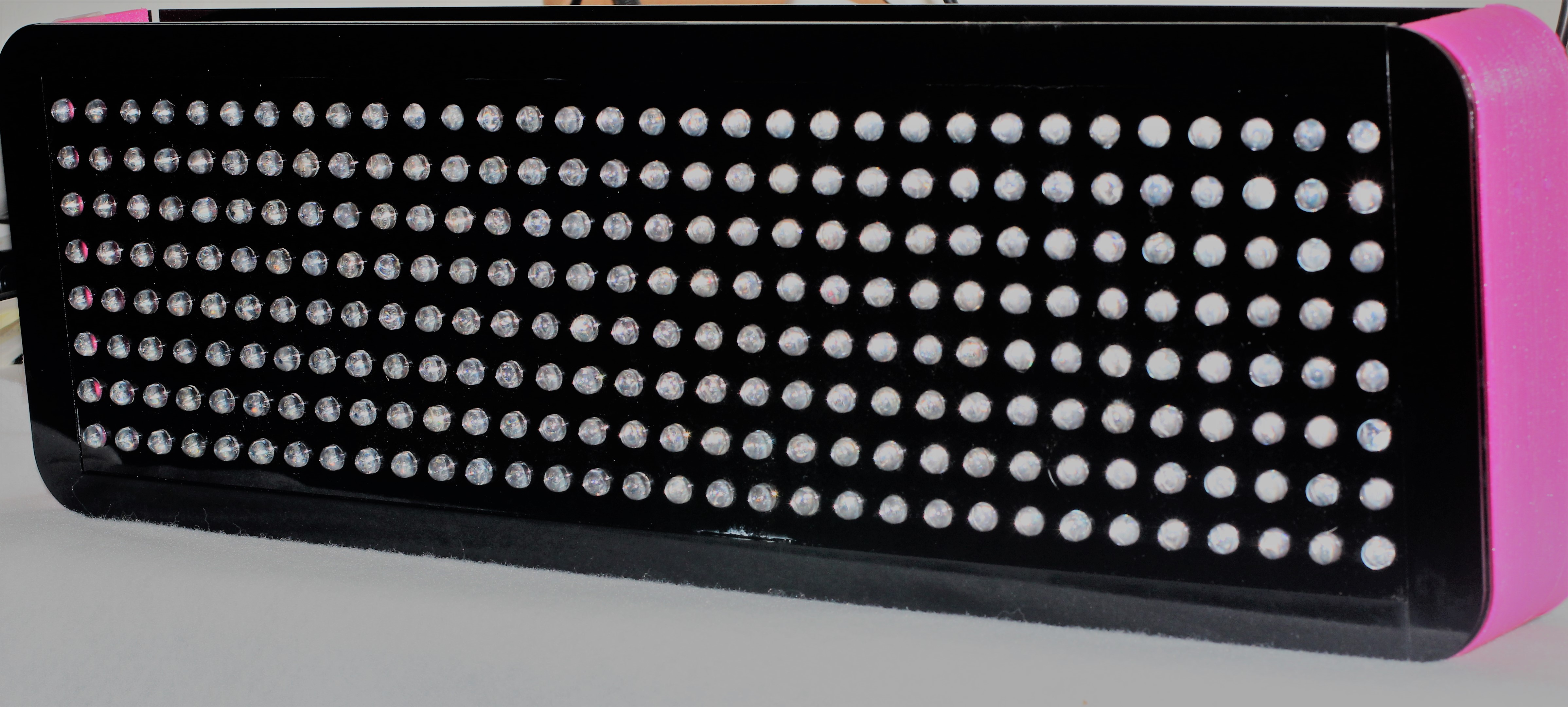
DIGIFAB DISPLAY
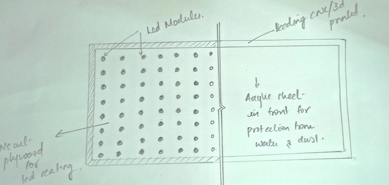
So the Stage is set and its time for action.As in the project management I am delayed by one day here itself at the starting of my project.The main issue was with the size of Trotec.It has a bed size of
30cm x 60 cm and my display is somewhat bigger than that.I was planning for a solution for the last two days in mind and now I decided to do led arrangement in a single sheet and the side beeding as seperate.
I planned to make a 3D print for the side beeding so that I could bolt it with the acrylic and complete my product.
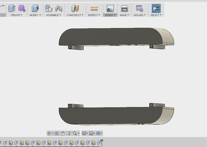
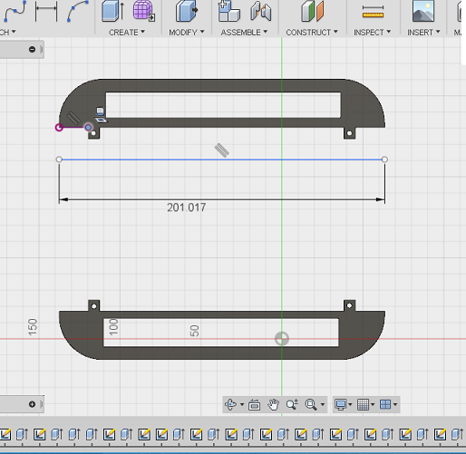
2D DESIGNING and 3D DESIGNING
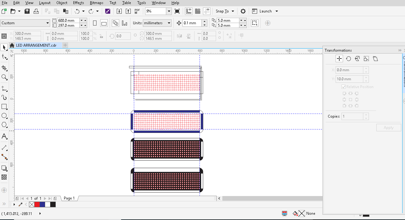
A products birth starts from its basic drawing.So the basic drawing should be that perfect.I choose CORELDRAW for doing my basic drawing as I am more used to it than INKSCAPE.
In coreldraw,keeping all the designing constraints in mind I started to draw.The led arrangement was done in such a way that all the holes are in a single sheet.Therefore maximum spacing between the Leds are
9 mm.I also designed the sides as curved,that design enriched the total look of my product.I also tried out different colour combinations(that was just a try)and exported the files to .SVG format for laser cutting.
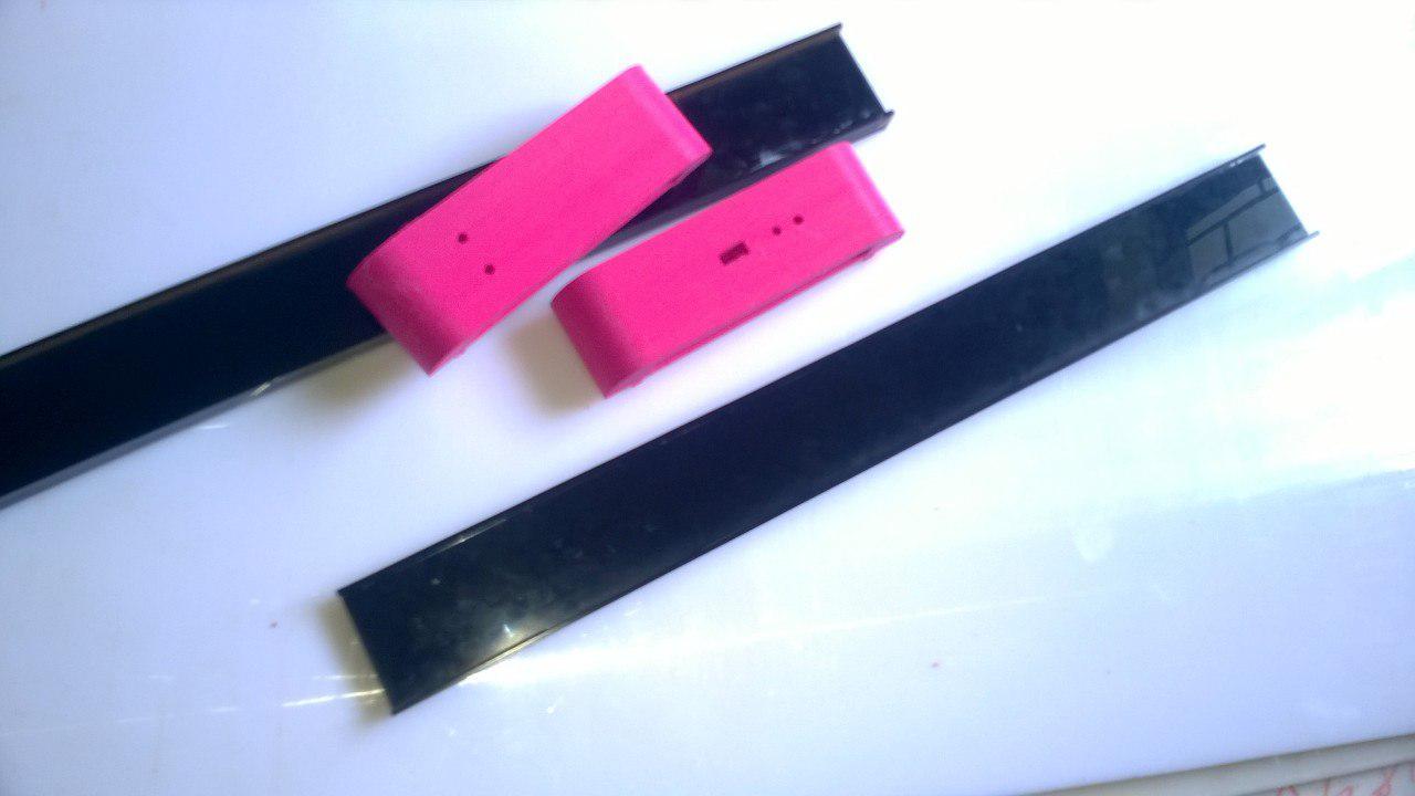
Also a small piece was designed like an inner contour on each four sides for acting as a beeding.
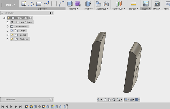
I need only the curved sides to be 3D printed and hence the same parts are saved as .DXF and opened in fusion and extruded for obtaining the 3D design.In Fusion,I gave some holes for taking the wires
out,and some allowances for screwing the parts to the acrylic.That wraps up the design section of my project
LASER CUTTING
I specifically needed a black colour acrylic for my led base because of its glossy look.In our lab we have precut 30 cm x 60 cm acrylic and I took one sheet.I have done my whole design in Coreldraw software
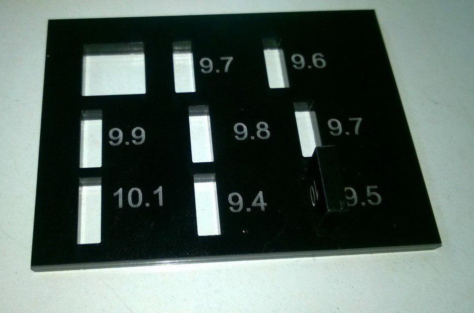
and exported to Inkscape to feed to the laser cutter.Before that housing for Led were found out using a test cut.From the results housing was found out to be 9.85 mm for 10 mm LEDs
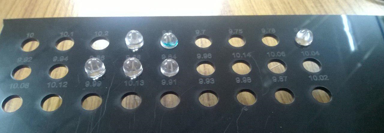
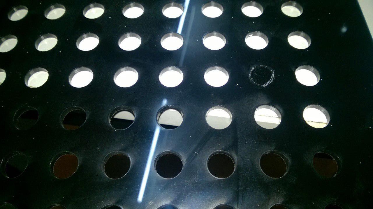
The round holes cut sometimes got over the acrylic and disturbed while cutting the other parts,hence resulted 5-6 holes uncut.These holes I have to cut with hand also used a round file to shape it.
That was not a tough job but time consuming.
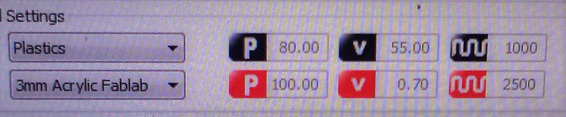
Trotec setting used for cutting 3mm acrylic:
SOLDERING AND FITTING THE LEDs
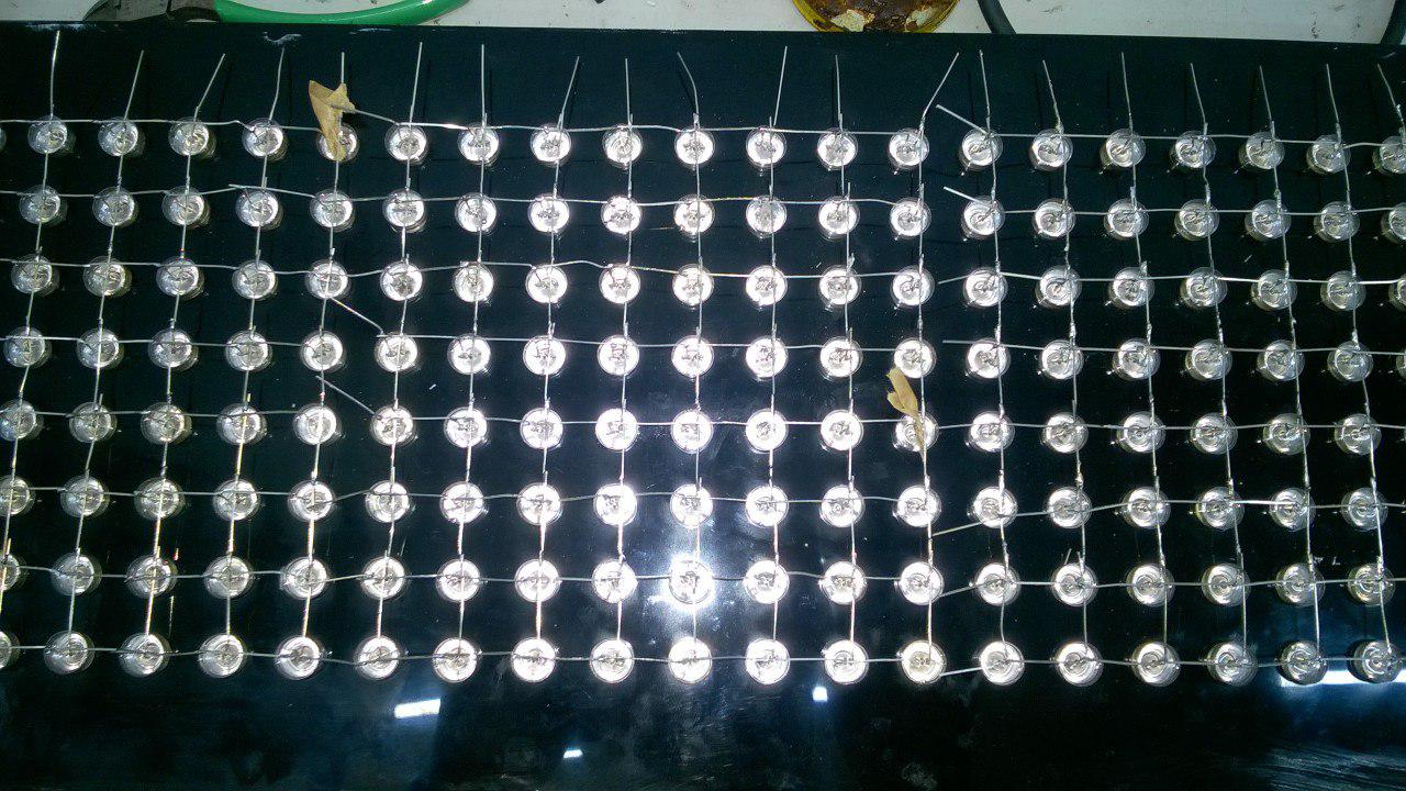
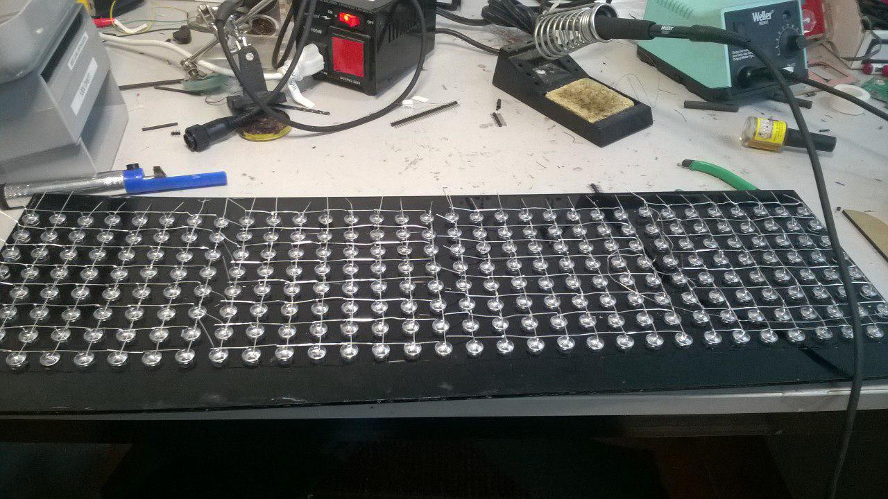
The leds were fixed on the acrylic sheet and started arranging the leds anode downwards and cathode to a side.During my test matrix making I bend the cathode leds towards each other and joined with a copper wire.But this time my instructor VinodKumar told me to bend it towards a side.The other one was easy to do but doing this way decreases the total thickness of the arrangement and looks neat.Bending the legs of 256 leds took almost 2 hours.From hereon I decided not to look at the time as that will not help.
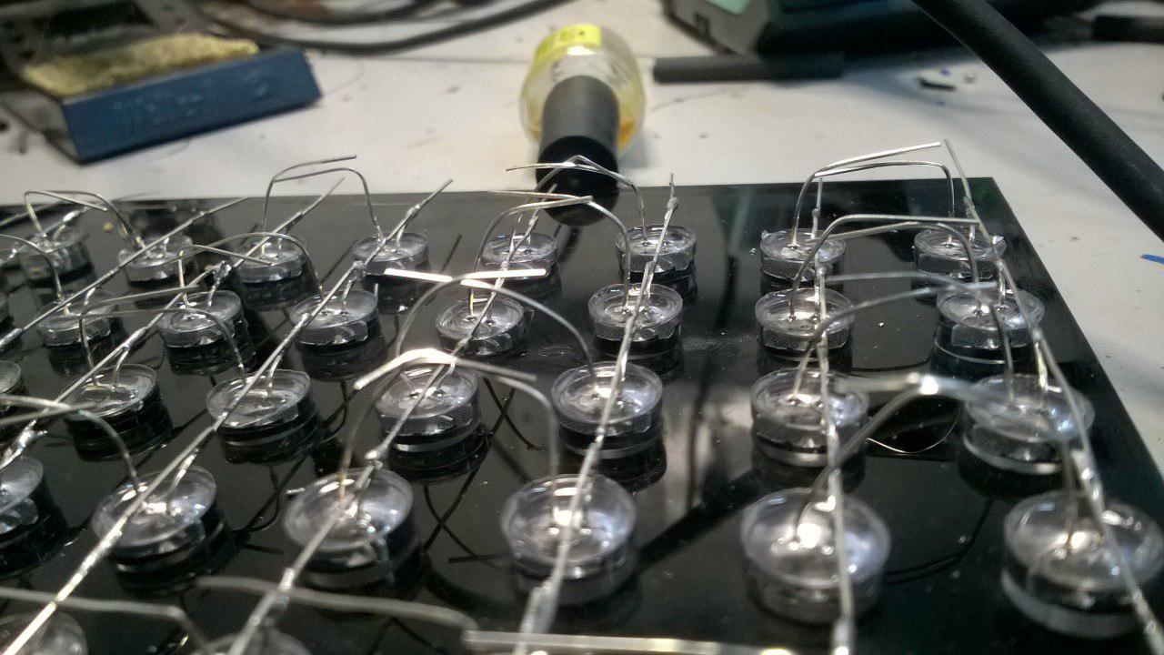
After a long cycle of soldering the four 8 x 8 matrix is ready.
This time unlike the test cut I wanted to test all leds so that I brought a button battery cell to test the leds.I have brought 300 Leds and due to some local packaging about 10- 20 Leds were lacking the legs.
While testing I found about 10 Leds not working and I kept them in a piece of thermocol near my table.So along with finishing the matrices the testing was also done simultaneously.

3D Internal press fit Assembly
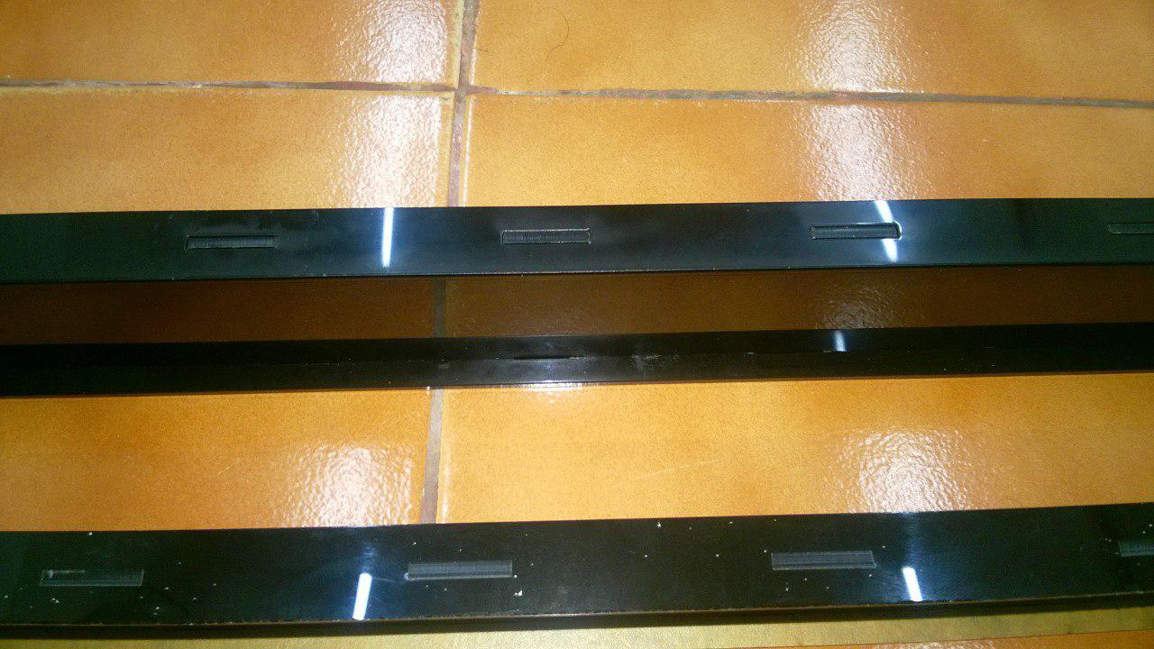
Since the 3D design was done with a thickenss of 600 mm,I made a pressfit for 600mm at top and bottom.This will be attatched to the back of the led arrangement acrylic.
For pressfit I have done a trail cut and the kerf of acrlic was found out to be 0.25 mm.The design was done considering the kerf for 3mm acrylic.The parts were cut and pressfit sides are assembled.
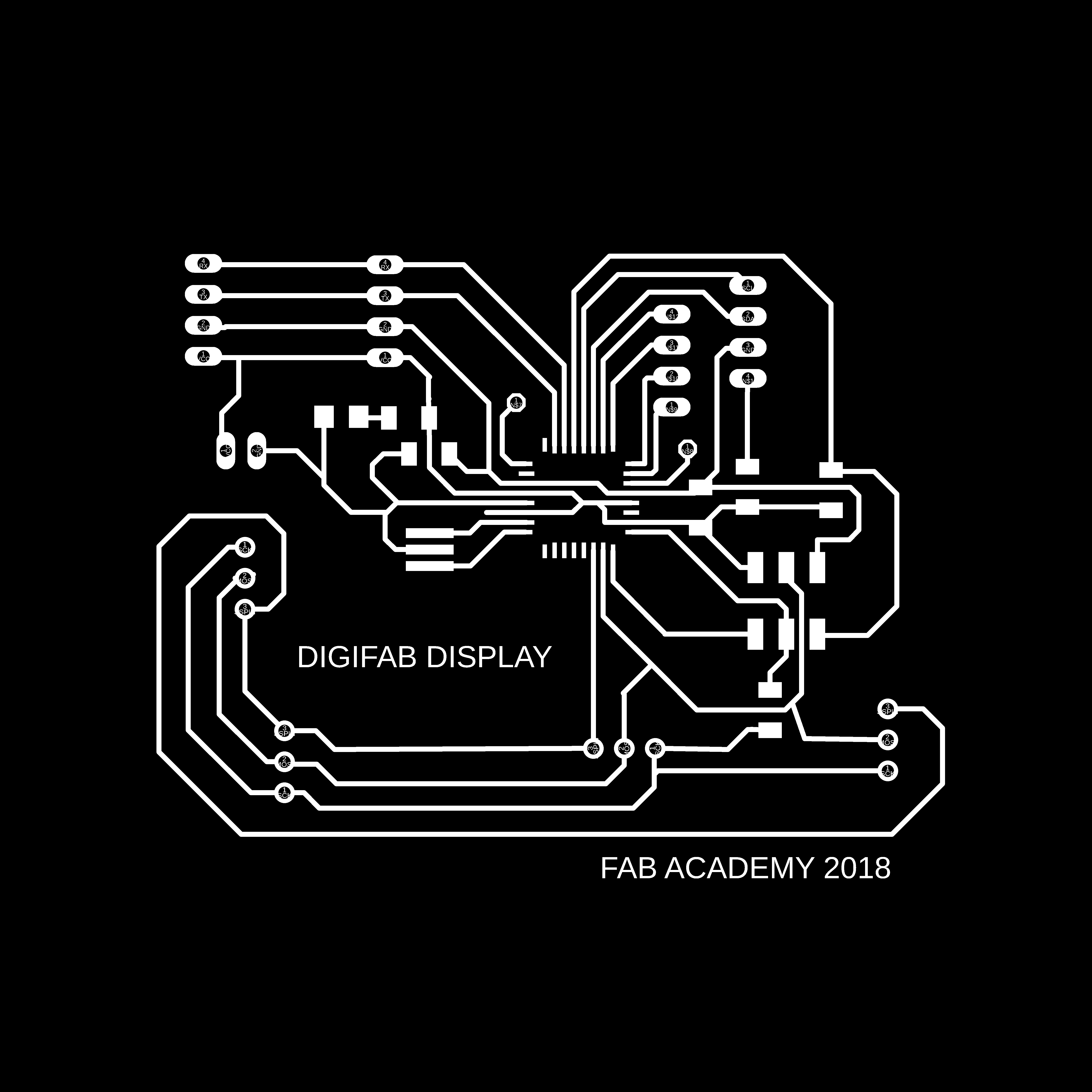
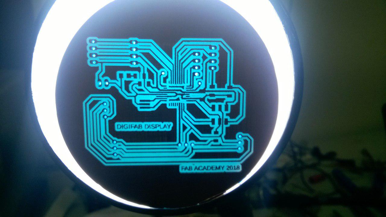
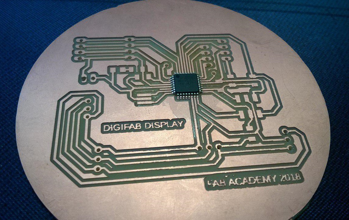
ELECTRONICS DESIGNING-learning manual route
I have to design a main board and 4 led driver boards for my DIGIFAB DISPLAY.The main board is controlled by ATMEGA328p microcontroller while the others have MAX7219 as the IC.So firstly I decided to draw the main board
(ATMEGA board).
ATMEGA BOARD
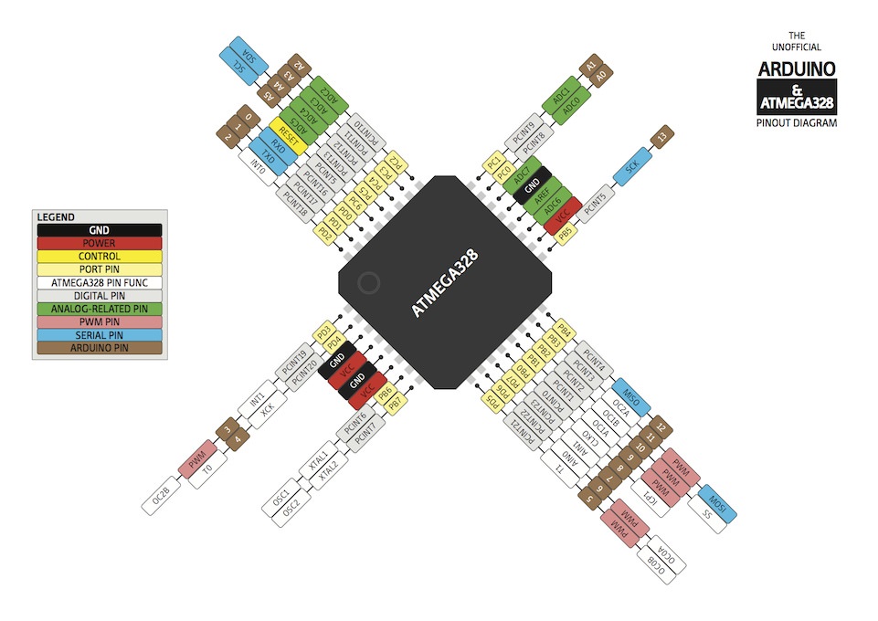
Requirements:-ATMEGA BOARD needs 20 MHz resonator,pullup resistor for reset and VCC, GND connection from outside.
My requirements are very less.I just need connection for SS(load),MOSI(master out slave in) and SCK(clock) for SPI communication for the board,
3 x2 header pin, ftdi connections ,bluetooth connections.Infact I have also give pinouts for I2C and interrupt pins(understanding the application of ATMEGA)
Also I connected a power led across VCC and ground to check the power status.
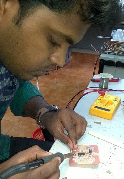
Manual routing for the first time but never felt any difficulty,it was an enjoyable job .Here are the routes attatched
After milling
LED driver board and its calculations
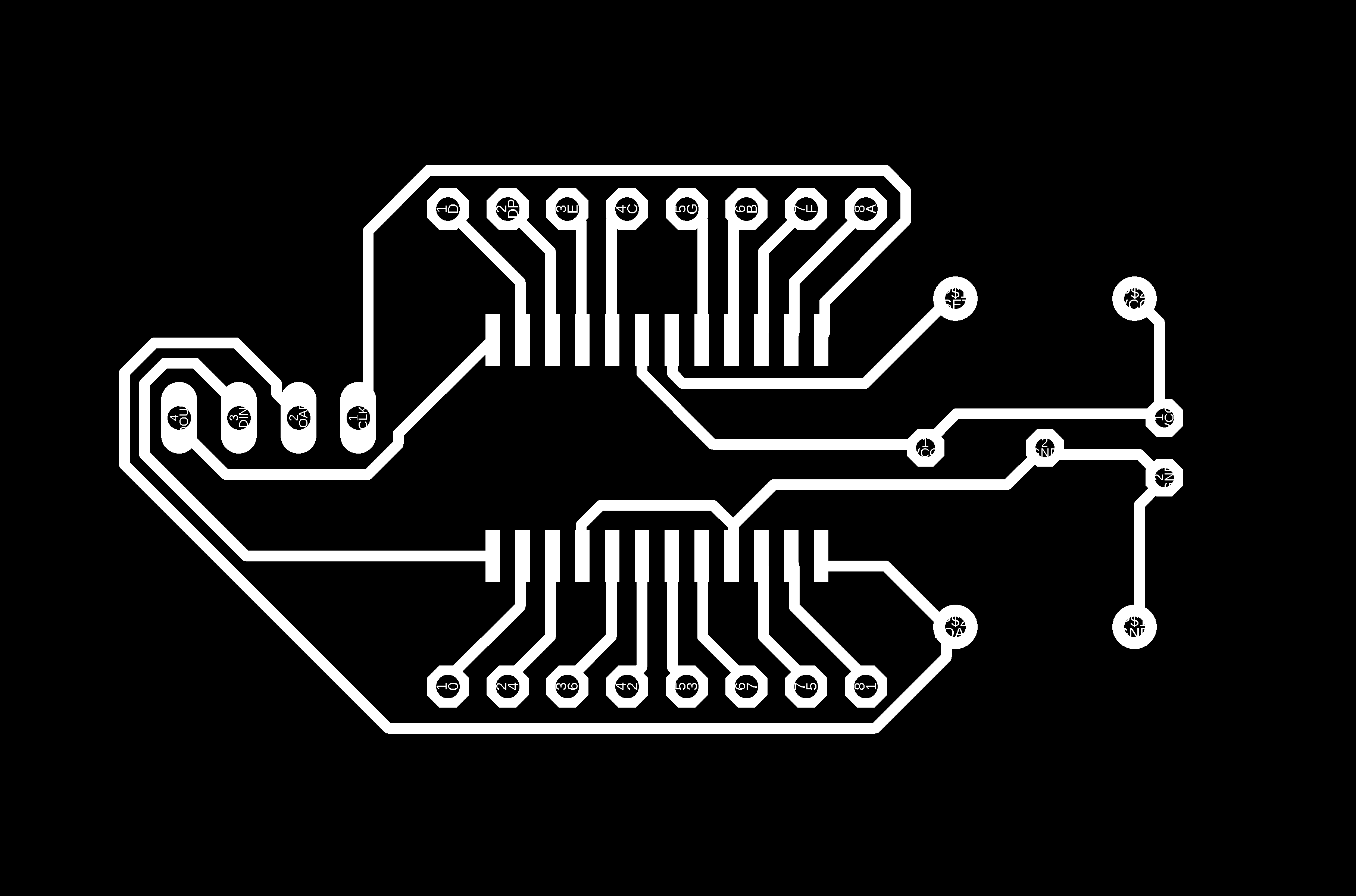
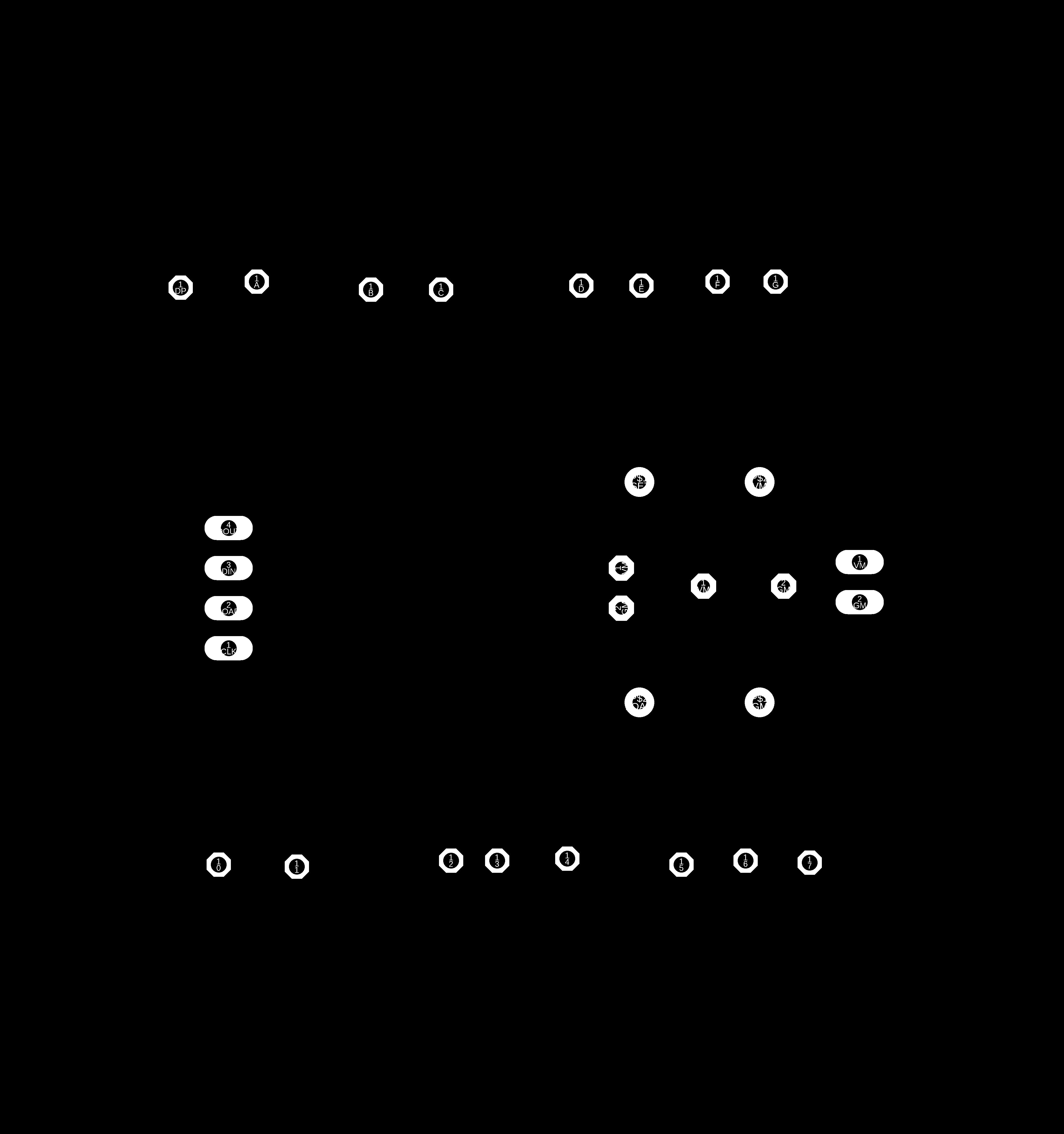
For the led driver board I have to give 8 pinouts for anode and 8 for cathode.The pins are jumbled so that I have to sit and manual route
them putting them in arrangement from cathode pins 0-7 and anode pins DP,A-G.This was a time consuming process and I finished it within a few hours.Later I noticed that
the board I made for testing purpose is 1/3rd of the size of this board.But this is very easy for connection and could be used as a customboard i.e.,if we want to increase the size of matrix just make a matrix mill a board and connect it with the other LED driver IC.
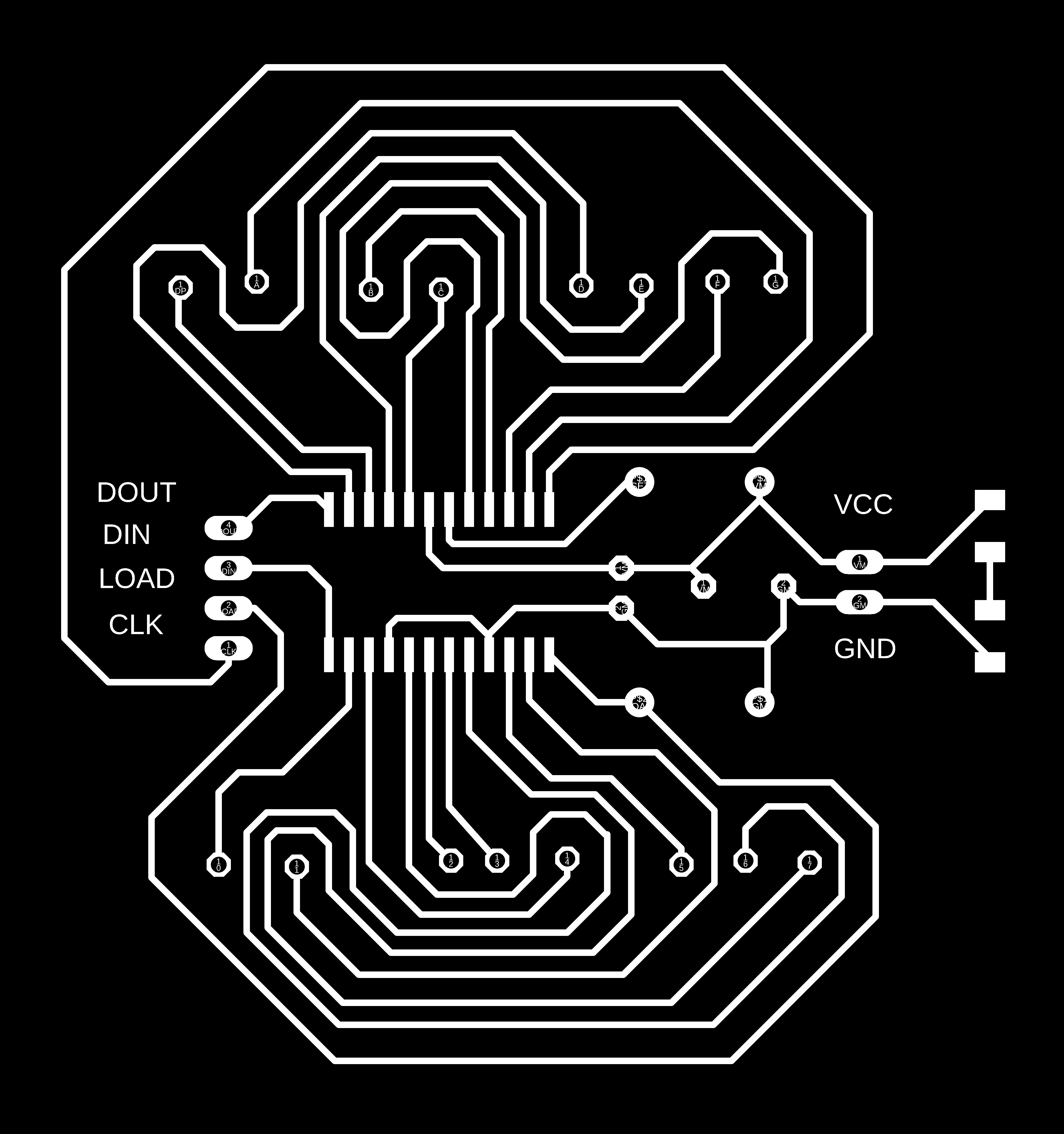
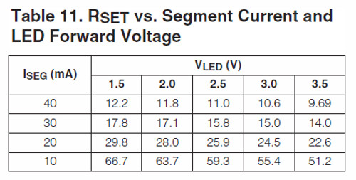
In the MAX IC board we need to connect a resistor across ISET and VCC,this resistor is thhe limitting resistor for all the leds in the 8X8 matrix so that we dont need
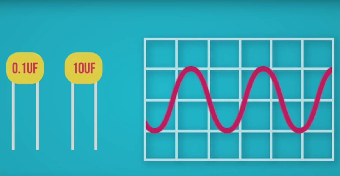
to connect a resistor for each leds.This is mentioned in the datasheet.Also we have to connect electrolytic capacitor and a disc capacitor for limitting the ripples and noise.
In youtube I found a explaining about max 7219 and arduino.1
The capacitor values are mentioned from this video as it is common for all but for the resistor we have to find the value from datasheet .It is dependent on the forward voltage and forward current of the leds.This changes from each led size and colour.So I have to find the forward current and voltage for my 10 mm blue colour Leds.This details was furnished from this . I found out the forward voltage as 3.2V and forward current as 20mA for blue Leds and a resistor between 24.5 ohm and 22.6 ohm is needed for my leds.
all these calculations were done while testing with a single 8 X 8 led matrix.
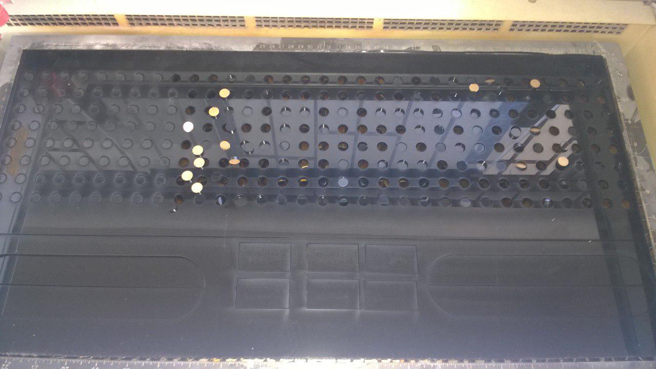
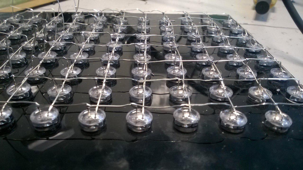
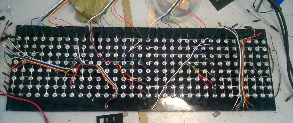
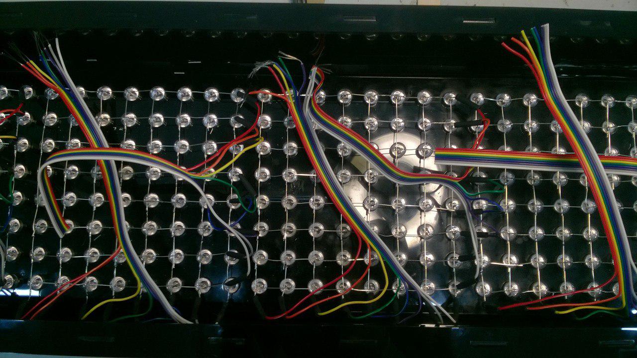
Connection and integrating the wires
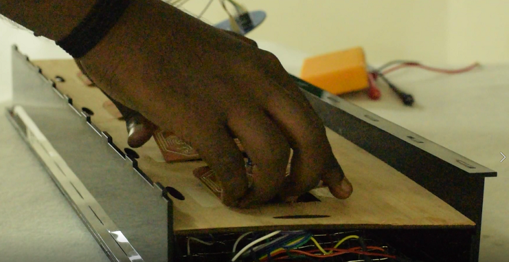
From the start itself I had kept the wiring in mind and to integrate this I had manually routed the LED driver board.I took 8 segmented Ribbon wire for connections. Firstly,I connected one end of the wire to cathode and anode of leds and used sleeves at the connection joints and secured them with hot air gun.You actually need a lot of patience to do this process.
After this I attatched the press fit assembly to the sides of the led arrangement acrylic sheet.
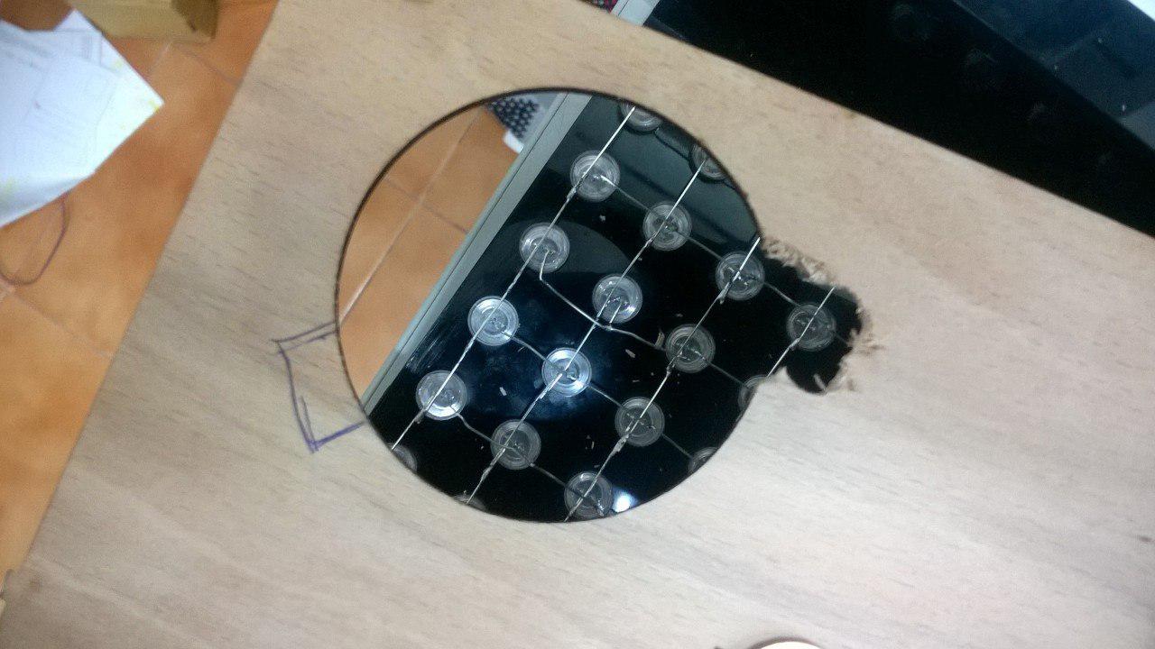
The next step as to cut a beachwood for seating the controller Boards.I designed the same in coreldraw and cut it in laser.
Later i found that the Mother board(ATMEGA) can't handle the hole and so I have to cut some space for the connectors.The boards were seated on the beachwood
and soldering the ribbon wires under the boards was very difficult task.My neck was paining in between and I took a break after finishing each 8x8 matrix.
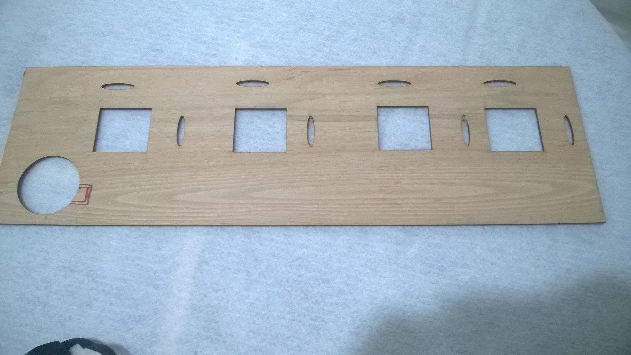
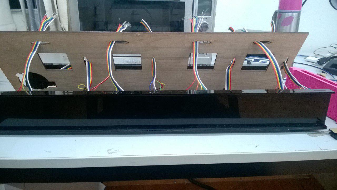
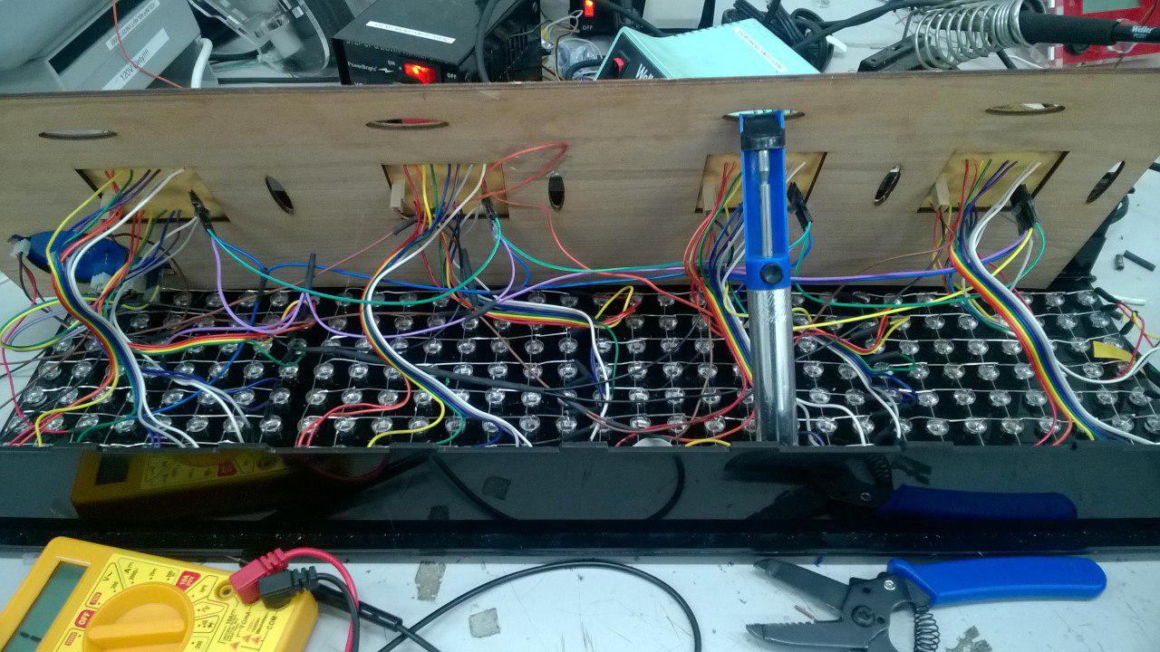
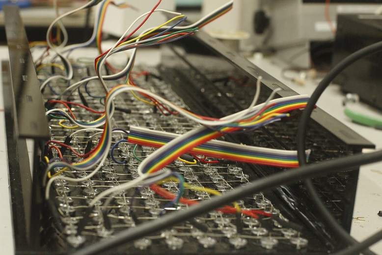
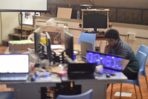
The first picture is actually my plan for wiring (for that only the oval holes were made) but that didnt go well.In the second image you can see me in the midst of connections to different MCU units,testing was done simultaneously with wiring
So my suggestion is to do the whole process in reverse.Start from soldering the wires in the MCU and finally do it with the led matrix.
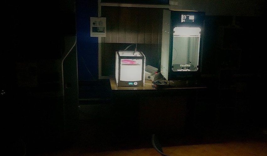
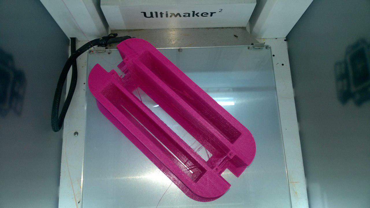
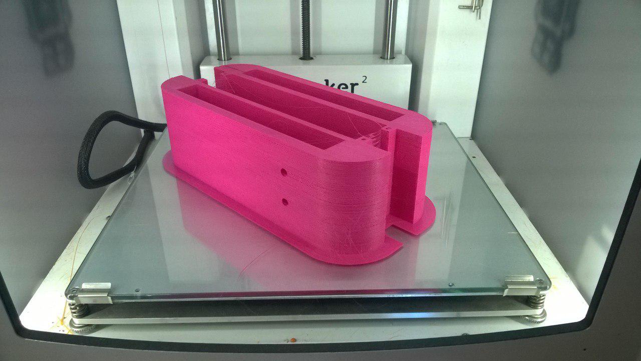
3D printing the sides
I have drawn the 2D earlier in CorelDraw and so I exported it into .dxf format and opened in Fusion 360.I extruded it to 600 mm ,gave some holes
for the wires to pass and connections.The model is given above in the design section.The print was very big and therefore the fill density was reduced as it doesnt affect my body strength.So the final estimated time was 18 hours for
the 2 sides.I started the print at night in Ultimaker and Eby put his print in Dividebyzero, a new addition to the 3D printer family at our lab and left the lab.The next day the print was ready.
Testing the display
The next day also the soldering process continued,assembling with the beachwood.Giving connections of VCC and GND to each board,and that day we worked overnight at our lab,and at morning 6:00 am I started to test my led display.This time my friend Akhil Hari who went for a small nap a few hours ago came with his camera and took my snap.I think he was still in the midst of his sleep as everything was outoffocus.
During the testing I found the data pin was connected reversely and after two tiles the letter gets mixed.I reconnected the data pin and it was working correctly.I was indeed happy and what left for me is to
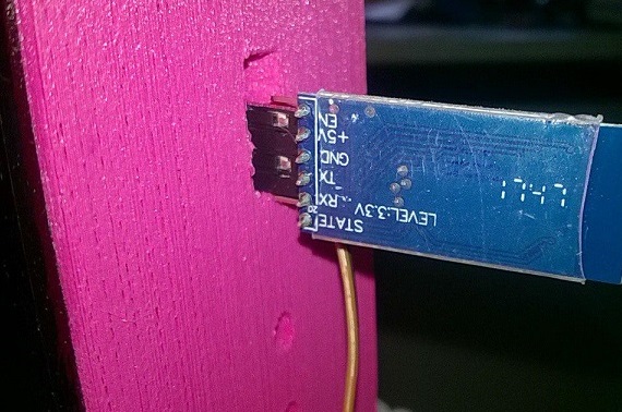
design the bluetooth app ,work with it and make the slide and video for presentation to NEIL and I have less than 24 hours more to do.
CODE
Coming to coding we have to be aware of the SRAM memory anf Flash memory available for our ATmega chip.It has very less SRAM memory complared to flash memory.The details
are as follows:
Flash 32k bytes (of which .5k is used for the bootloader)
SRAM 2k bytes
Flash memory and EEPROM memory are non-volatile (the information persists after the power is turned off). SRAM is volatile and will be lost when the power is cycled. If you run out of SRAM, your program may fail in unexpected ways; it will appear to upload successfully, but not run, or run strangely.Therefore we can upload our program in Flash memory of ATmega 328p chip using the keywork PROGMEM. Read more about PROGMEM
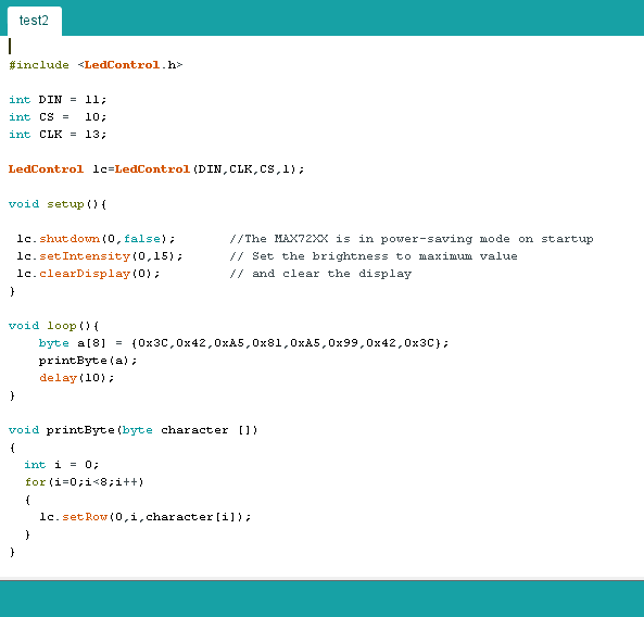
Coming to the coding I was keeping this in mind and searched for code storing in Flash memory.I reffered works in Instructables,circuits4you,Electronoobs and howtomechatronics
I have modified the code by electronoobs to my requirement,defined the baud rate for software serial communication which was not done in the code.Below given is the code i used:
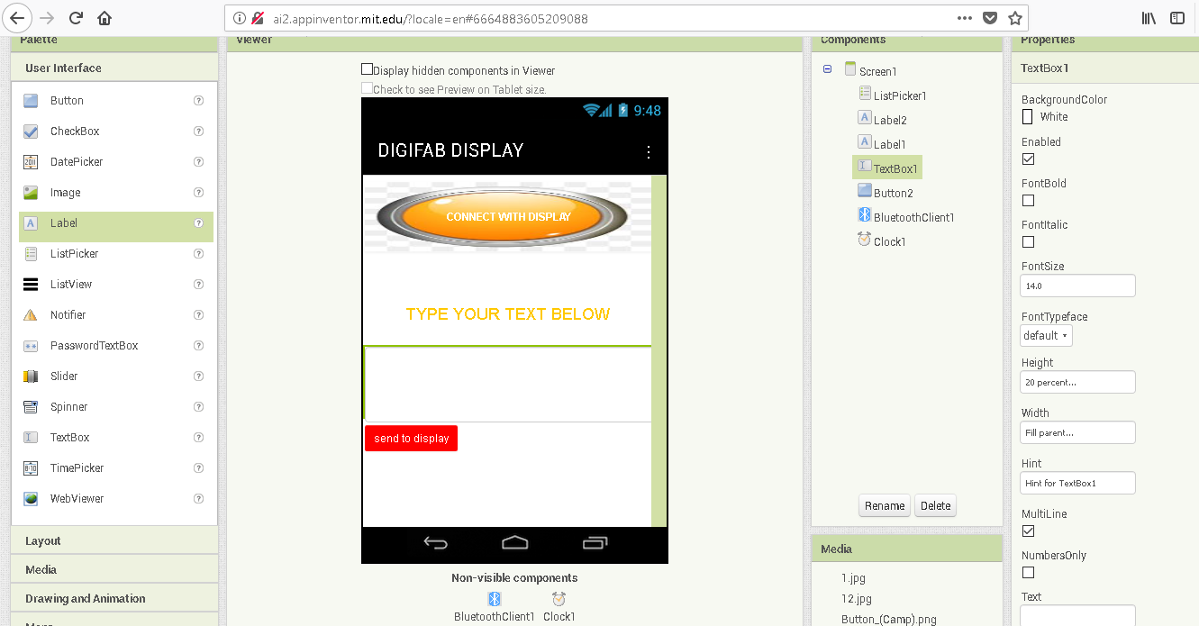
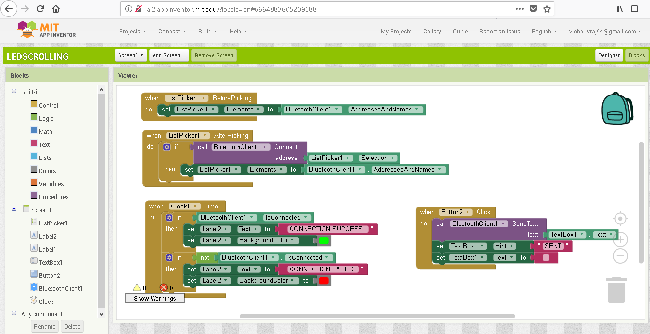
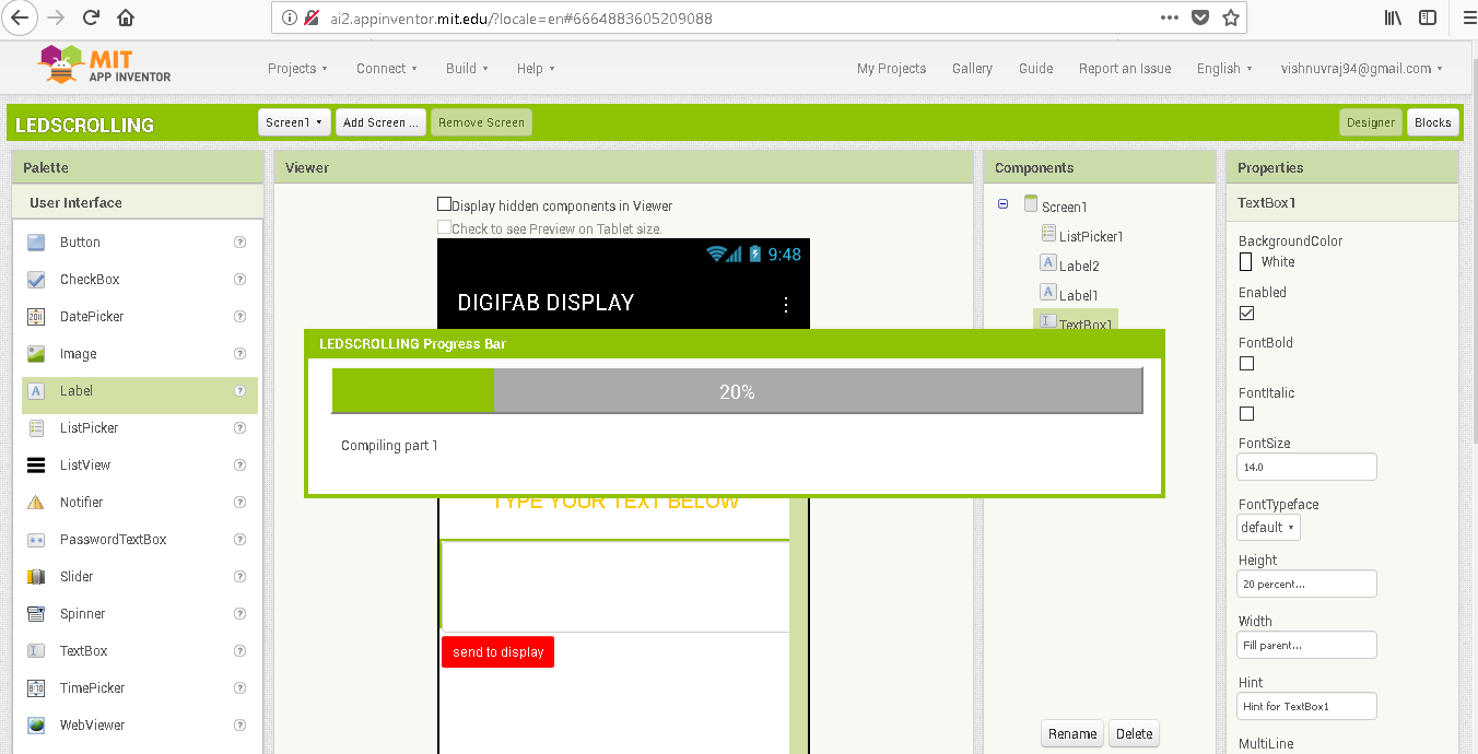
Designing the Bluetooth app
I have earlier experience with the MIT APPINVENTOR for my interface week and therefore it was not a difficult process for me to design the app.As i was in a hurry I did not gave much time for modifying the look of the app.The screenshots are duly attatched:
WORKING OF THE DIGIFAB DISPLAY
ASSEMBLY TO THE FINAL LOOK


BILL OF MATERIALS
| Sl.No | Part Name | Source | Quantity | Total Amount (in INR) |
|---|---|---|---|---|
| 1 | led 10 mm | Ebay | 300 | 855 |
| 2 | MAX 7219 IC | Aliexpress | 10 NOS | 300 |
| 3 | 8 mm led | 5V powersupply | 70 | 600 |
| 4 | Button cell battery | Local market | 1 | 10 |
| 5 | 3mm Acrylic (Black) | Fab Lab Inventory | 300 mm x 600 mm | 200 |
| 6 | 3mm Acrylic for beeding and sides (BLACK ) | Fab Lab Inventory | 300 mm x 600 mm | 200 |
| 7 | FR1 PCB Blank | Fab Lab Inventory | 70mm x 70mm x 5 nos | 100 |
| 8 | AtMega 328P | Fab Lab Inventory | 1 | 150 |
| 9 | 20 MHz Resonator | Fab Lab Inventory | 1 | 10 |
| 10 | 10 KOhm Resistor through hole | local market | 4 | 10 |
| 11 | 10 KOhm Resistor | Fab Lab Inventory | 1 | 2 |
| 12 | 0 Ohm Resistor | Fab Lab Inventory | 4 | 8 |
| 13 | 10 uF Capacitor | Fab Lab Inventory | 1 | 10 |
| 14 | 10 uF and 0.1 uF Capacitor through hole | Fab Lab Inventory | 10 each | 10 |
| 15 | connector 2 and 3 pin | Local Market | 15 | 70 |
| 16 | ISP Header Pin | Fab Lab Inventory | 1 | 5 |
| 17 | Pin Head | Fab Lab Inventory | 1 | 5 |
| 18 | Wire | Fab Lab Inventory | couple length | 100 |
| 19 | LED | Fab Lab Inventory | 5 | 10 |
| 20 | 499 Ohm Resistor | Fab Lab Inventory | 5 | 10 |
| 21 | 3D printing | Fab Lab | 150 gm | 500 |
The total cost comes around Rs 3200 i.e below 42 dollarswhereas the one available in commercial market cost over Rs.6000.
THE HERO SHOT
SLIDE FOR PRESENTATION
VIDEO FOR PRESENTATION
PROJECT PRESENTATION TO NEIL
We had project presentation on 18th june evening,Boston time,for us actually it was 19th june early morning 3:00 am.Everyone was excited to present their projects ,me too with littile bit nervousness
.After watching my presentation, NEIL congratulated me telling "you took it far".
FUTURE IDEAS
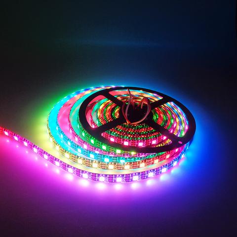
I am very happy to complete this project successfully and in future I would like to do a scrolling display with WS2812B RGB self adressable led strip,
We could even display videos with that.Bit higher on the cost,anyway I have already bought a 5m roll to start with and practise with programing.
Also coming to this project,I would like to try with some other library like PAROLA library to display texts in various fonts and control the effects while scrolling.Just stepped in to, Lot of distance to cover..THANK YOU FAB ACADEMY!

FAB ACADEMY 2018 by VISHNU V RAJ is licensed under a Creative Commons Attribution-NonCommercial-ShareAlike 4.0 International License.