Using the Vinyl Cutter
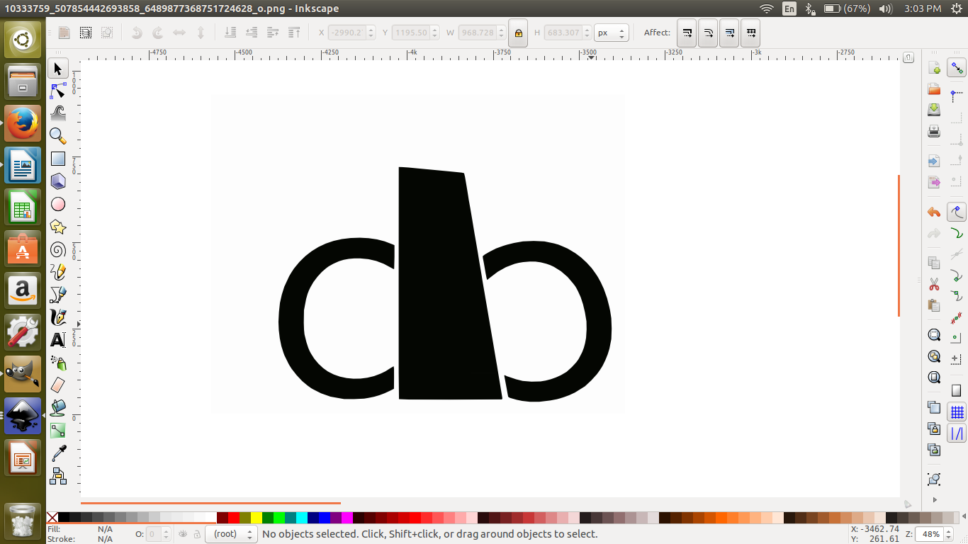
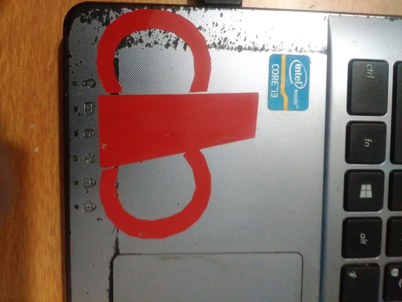
Week 3, our first exposure to using a Desktop-sized Vinyl Cutter. I liked the idea of making and "cutting" my own stickers, especially understanding how the stickers themselves would be able to be peeled away from their adhesive-surfaces.
At the Fab Lab Kerala, we have a Roland GX-24 (CAMM-1 servo Desktop Sign Maker). How I made a sticker using the Roland GX-24 Vinyl Cutter
Logging into the system to which the Vinyl Cutter was connected, I checked to see whether FabModules was installed
Upon confirmation, I opened up the fab dialog window to input my sticker .png file with the following values:
From Input Format = image(.png)
To Output Process = Roland vinylcutter (.camm)
This generated the make_png_camm Workflow:
Upon uploading my .png image under the make_png_camm dialog window, I chose "vinyl" under the drop down menu and generated the .camm file to send to the Vinyl Cutter by selecting the force (g) = 90
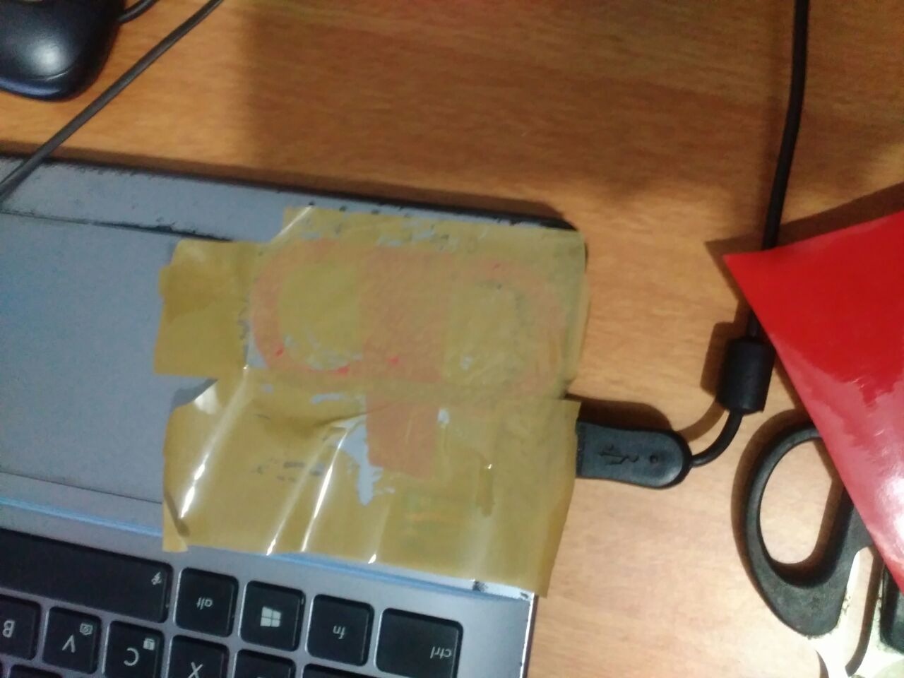
I powered on the Vinyl Cutter, navigated the menu to choose the "Select Sheet *Piece" option, and loaded the sticker paper according to the origin line on the cutter

After obtaining the design files, what I did was that took print of it. So for that I logged into the system in which vinyl cutter is connected.
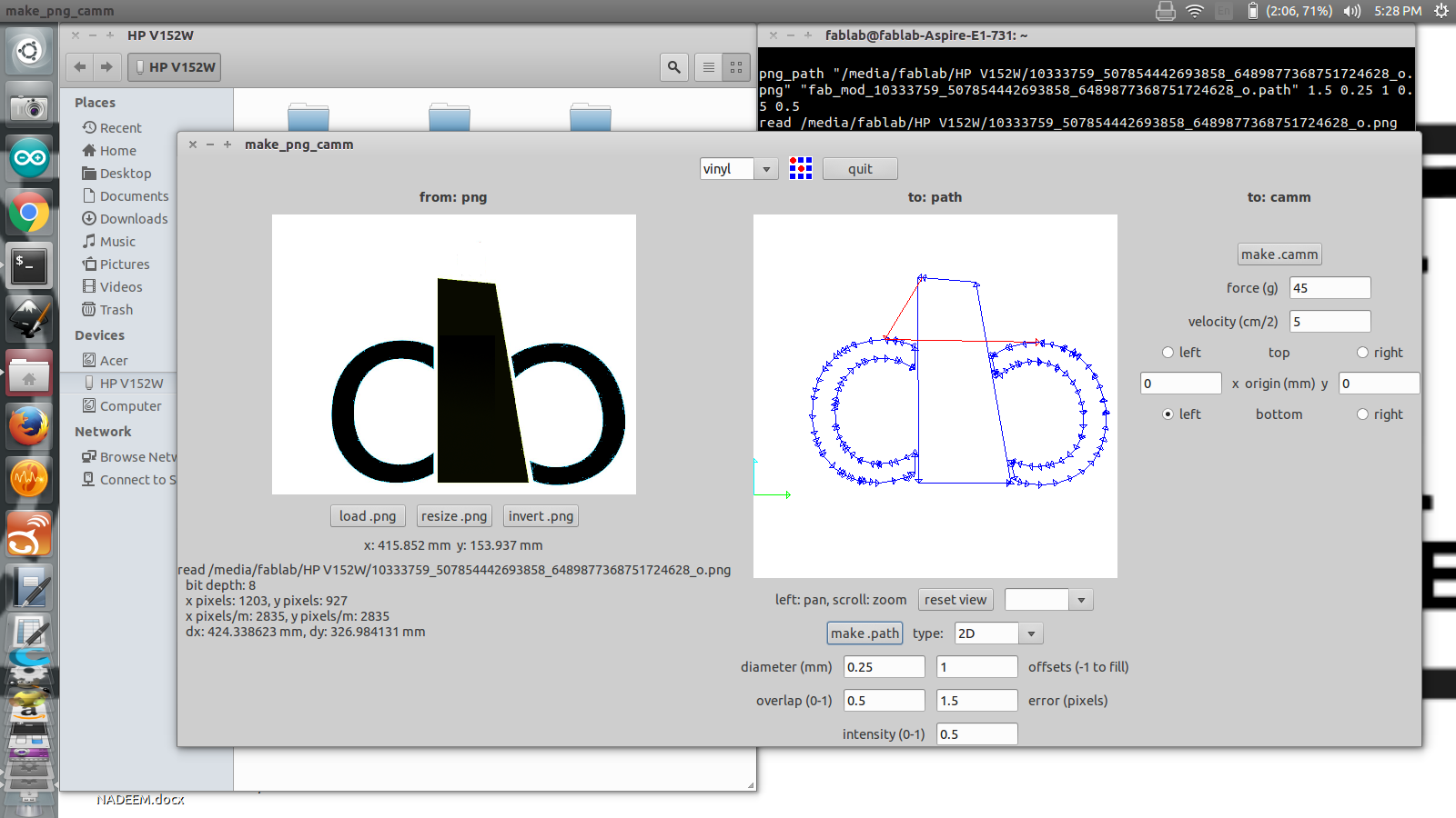
There I selected vinyl as material and then I made path so that the png format image that I entered has changed to the vector form. Then I started cutting.
Before cutting we have to make sure the material we placed should be aligned in a right manner
.
Using the laser cutter
The machine we use is Trotec Speedy 100 which houses a CO2 laser which have enough power to cut through wood some plastics, cardboard, acrylic etc. It cannot cut metals but can engrave on its surface.
I have expirimented using cardboard.
I used onshape to create my 2D image as onshape is parametric and after converting that into .solidworks after converting it into .dxf in solid works,then I used rhino to make that image into 2D.
Then by using machine I created my parametric model.
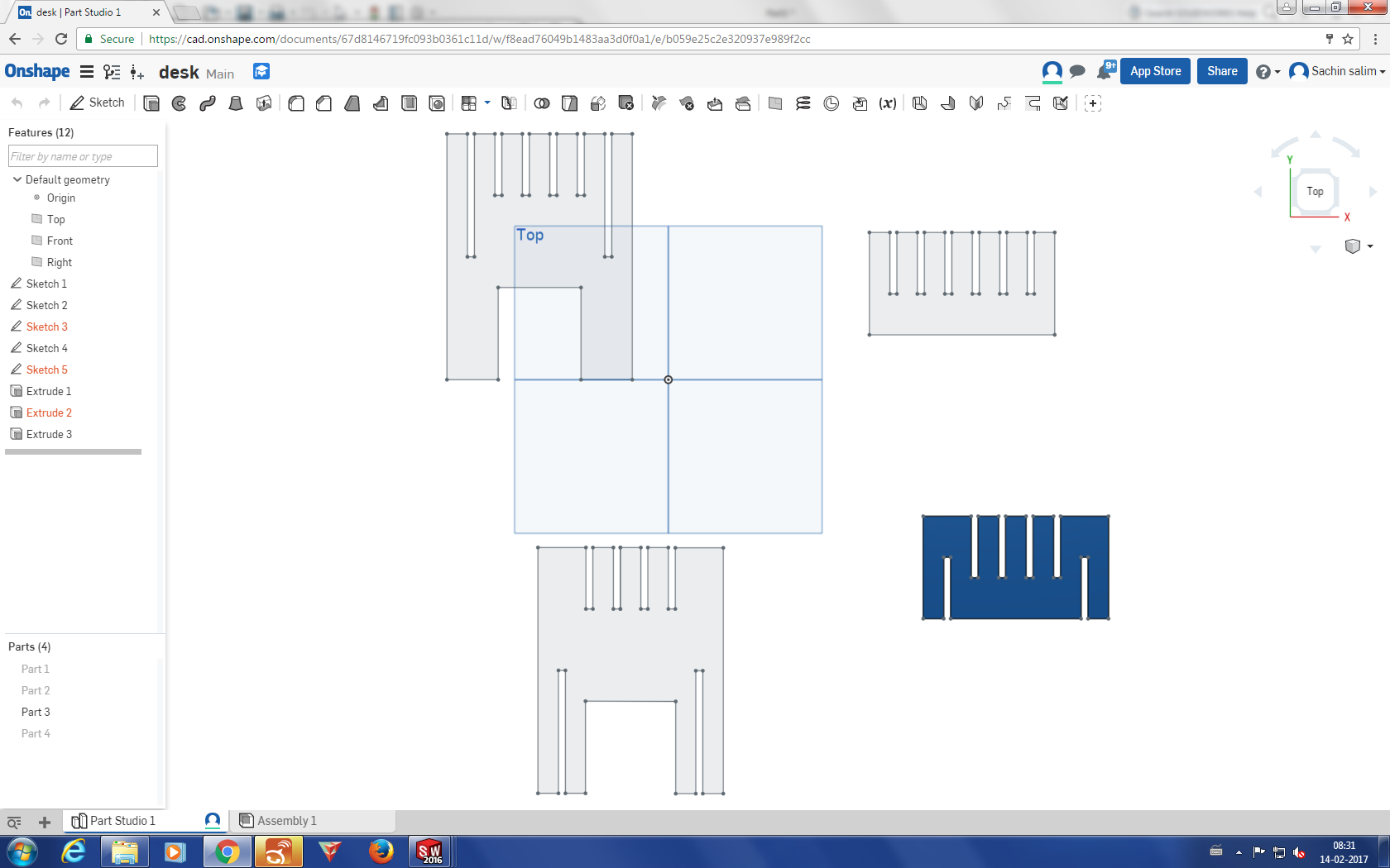
Following is a screenshot of the parametric dimensions of the sketch in OnShape.

Here I basically have four parts for making parametric model. With these four parts, my actual idea was to make a desk.
For part a I need 2 pieces, total length is 9.4cm, each section 10cms and .34cm as kerf as I am doing my work in cardboard.
Second part also I needed 2 pieces. So my four edges are covered.
Third part was to make parallel sections. The length I selected was the same, but the width I chose was 5cm.
Fourth part was as of the same size.
The next thing was that where should I design or whic platform should I select for designing. Finally I chose solidshapes which is an online designing platform for making my design.
After designing it, I exported my file into solidworks format.
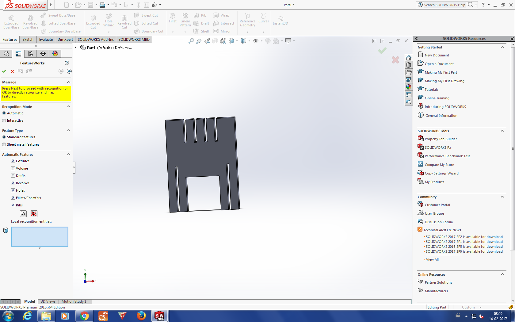
Then I opened my files in solidworks, where I could check whether the design I made was parametrically ok or not.
Then I exported my files into .dxf format in solidworks
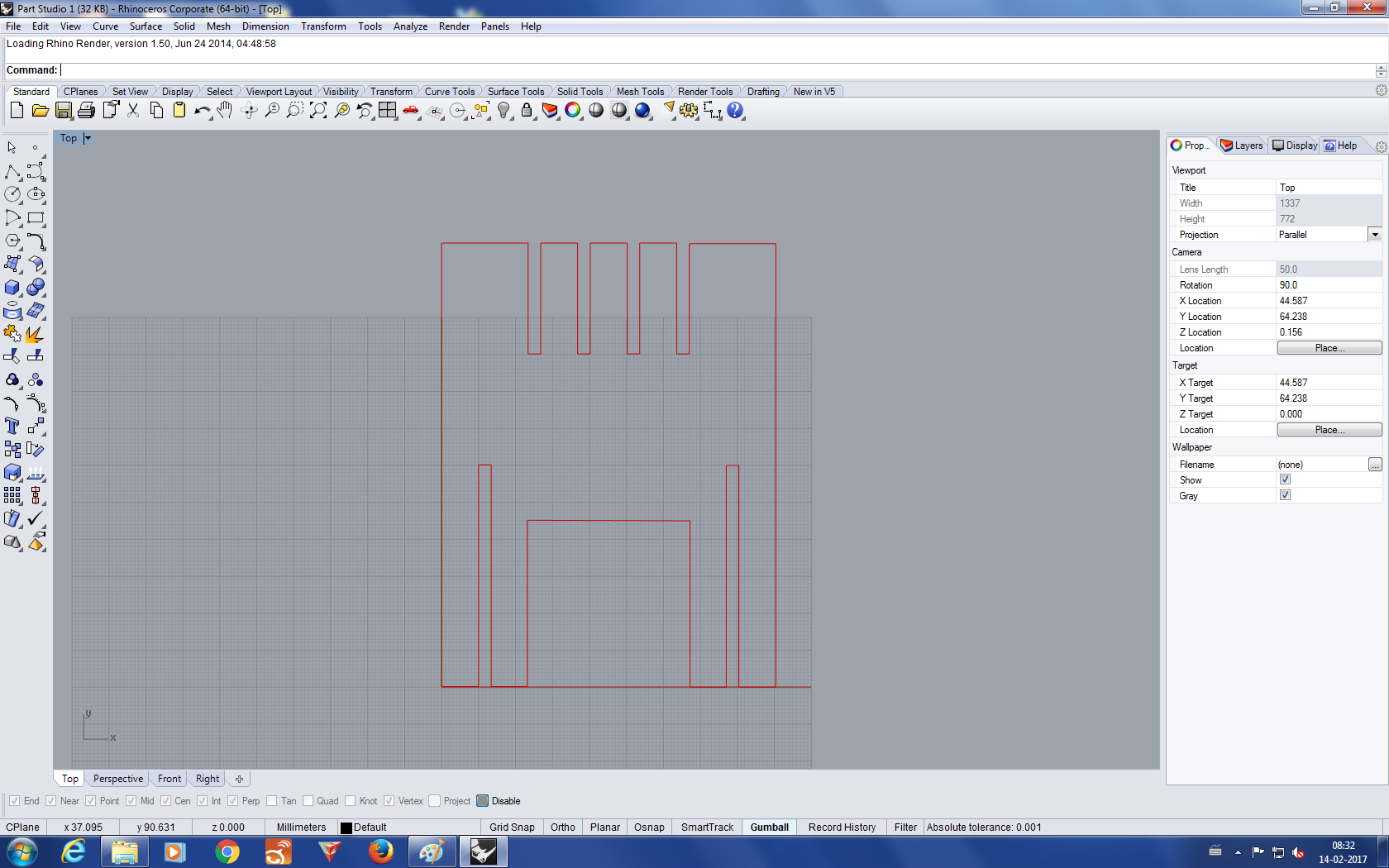
Then I imported the .dxf files in rhino.
There I convereted the image into 2D by make2d
Then I grouped all the images and alligned in a pefect manner in rhino so that no sheets should be get wasted.
Set the origin and make sure the filter is on brefore doing the work.
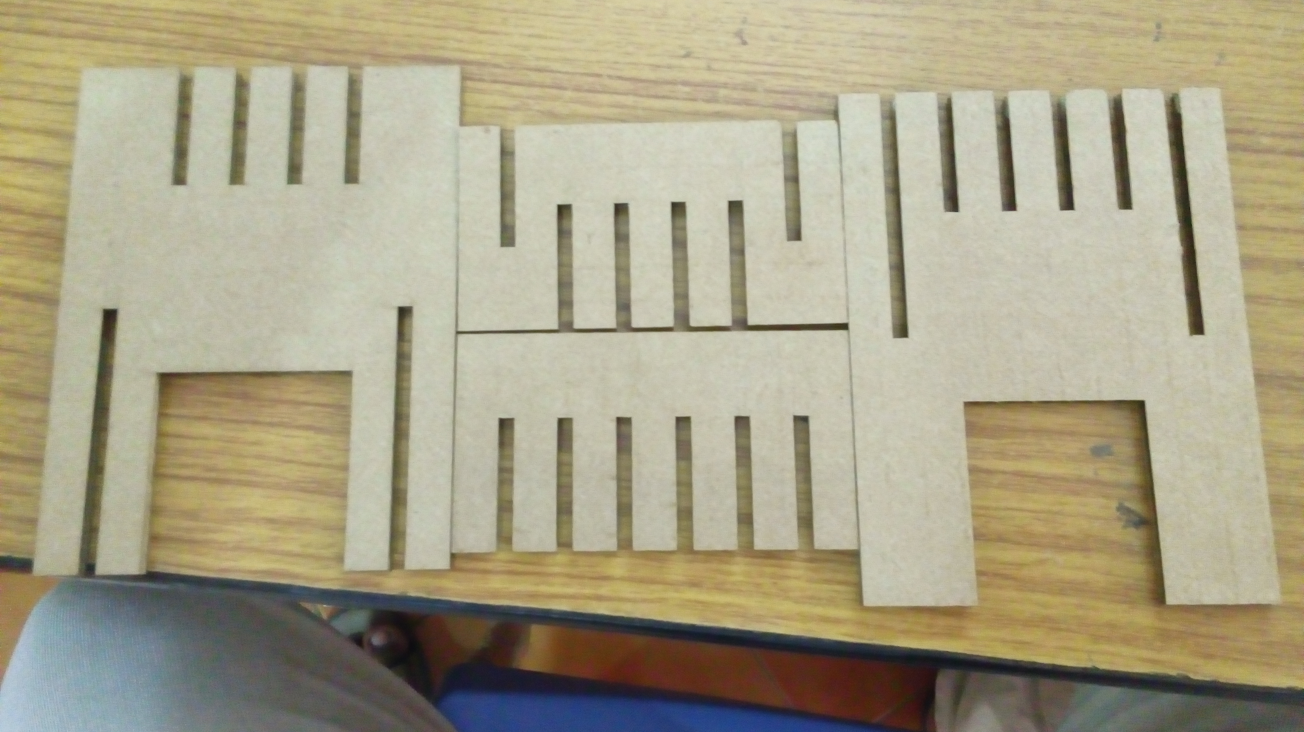
My laser cutted pieces are obtained.
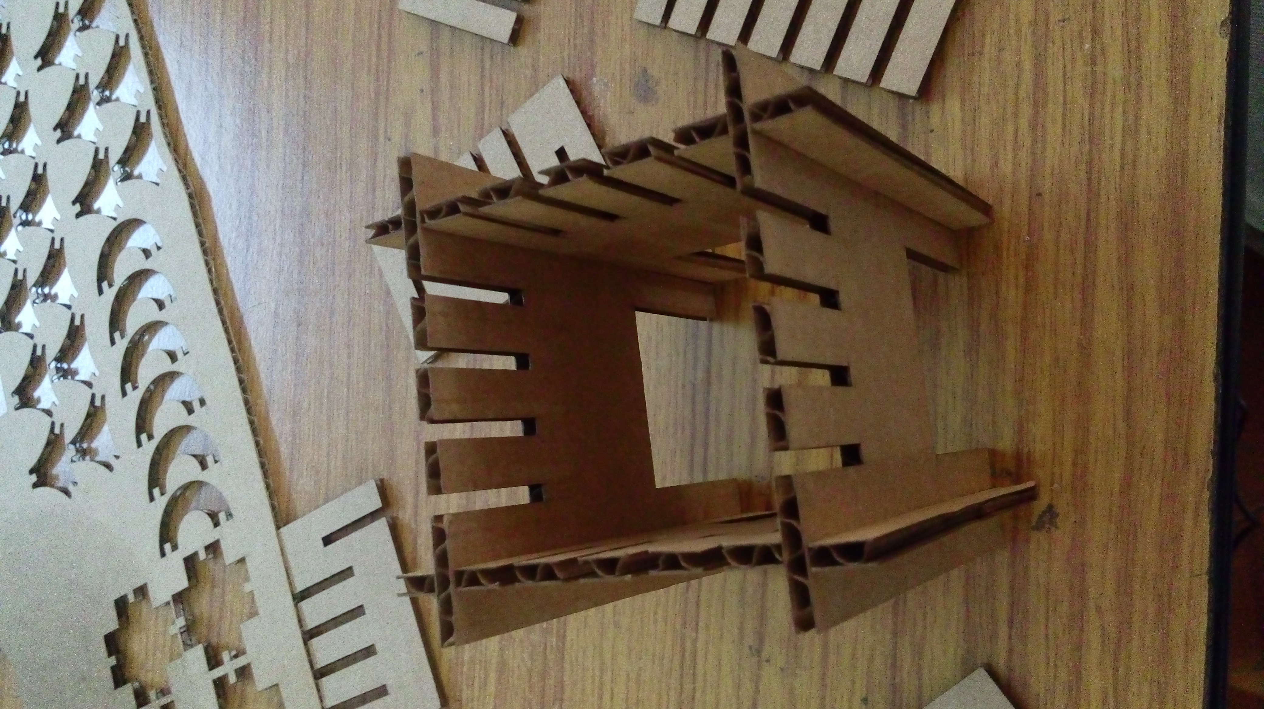
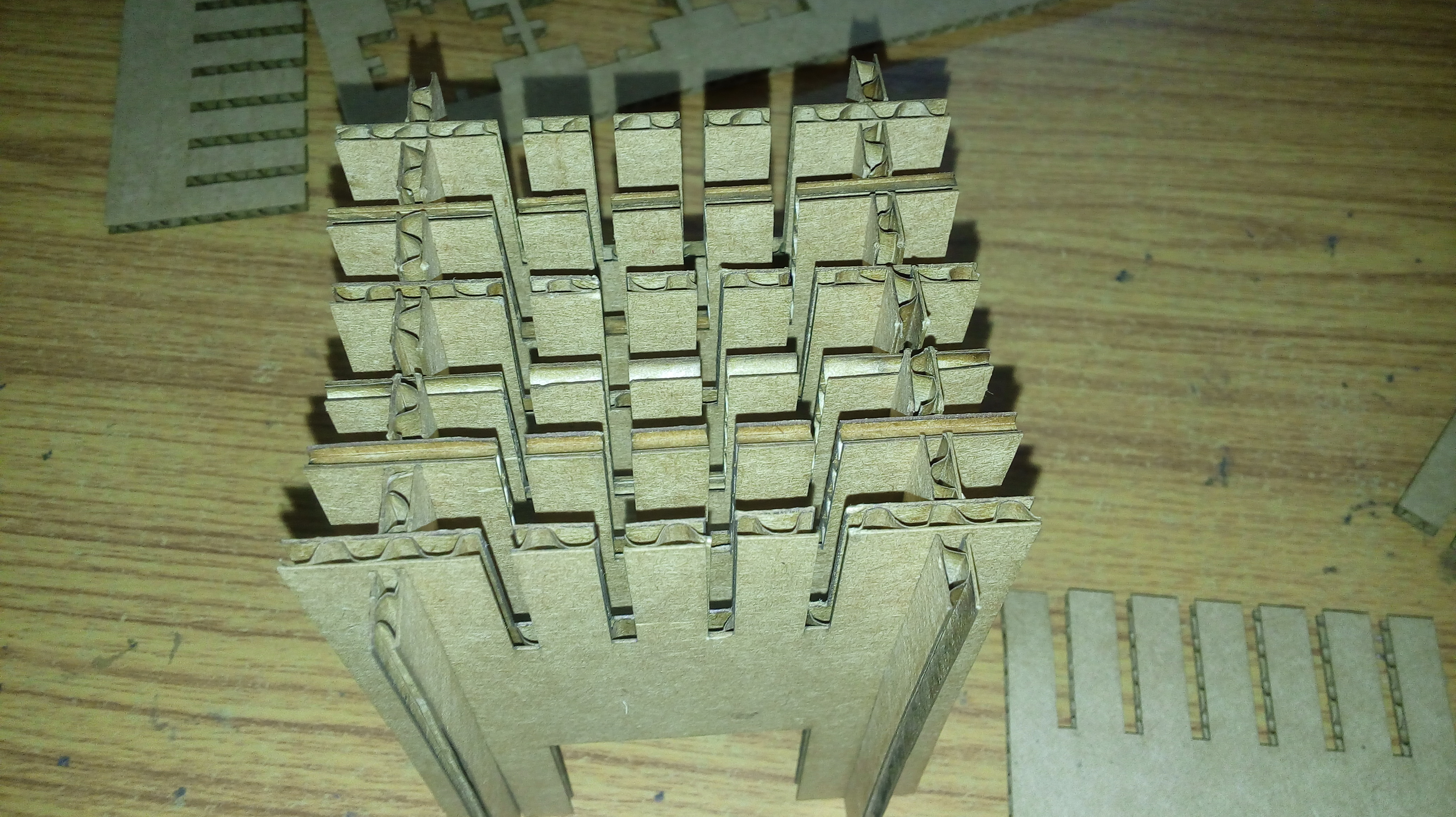
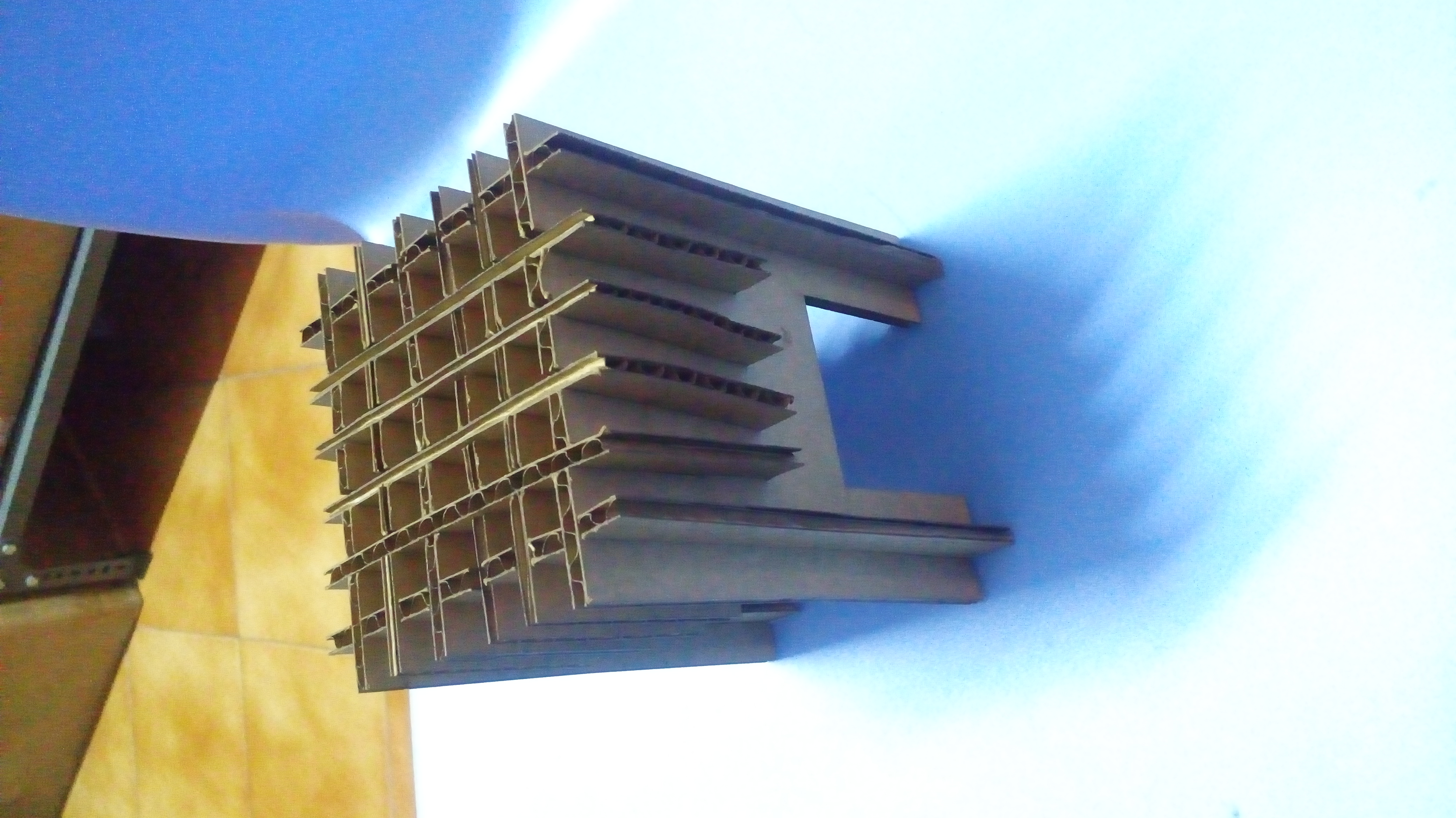
Then I assembled all the pieces.
Group Assignment
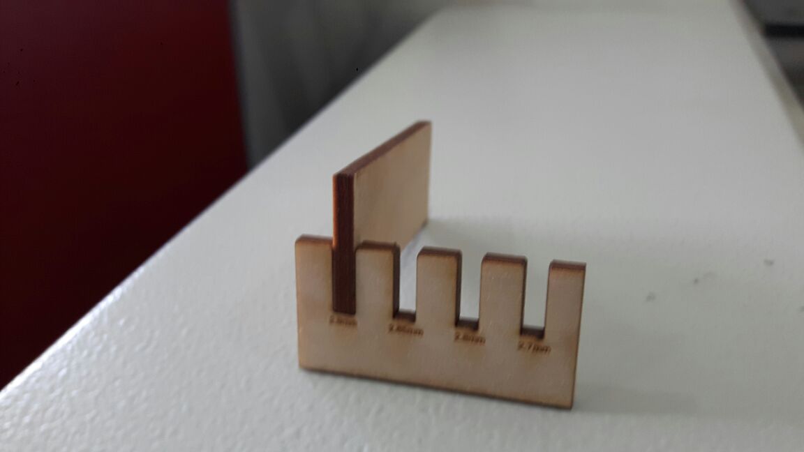
Our group assignment eas to find Kerf which is important in making pressfit.
.The laser burns away a portion of material when it cuts through. This is known as the laser kerf and ranges from 0.08mm to 1mm depending on the material type and other conditional factors. The prime factor that affects Kerf is material properties and thickness. Secondary factors are how much the laser takes away like the focal length of the lens and pressure of compressed air.
With some experiments, we found that the kerf allowance that needs to be given for cardboard in our lab is 0.35mm each cut edge. This value was further used in my press fit assembly as a variable in Solidworks, which could be changed later based on different material.
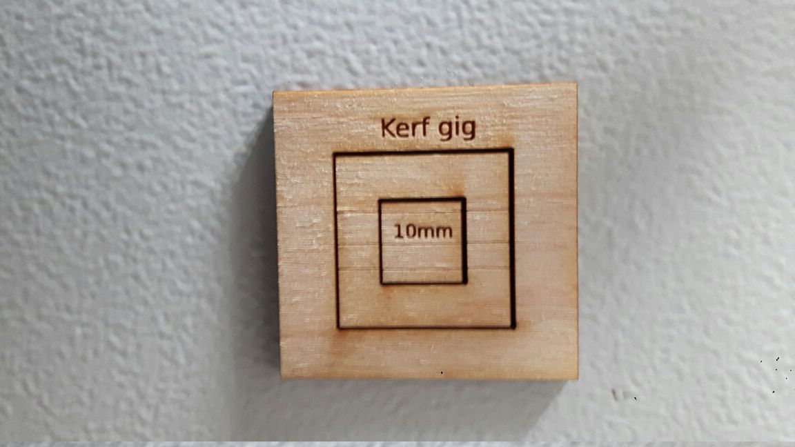
Cardboard is 0.35mm
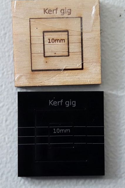
Acrylic is 0.488m
Craftwood is 0.3mm
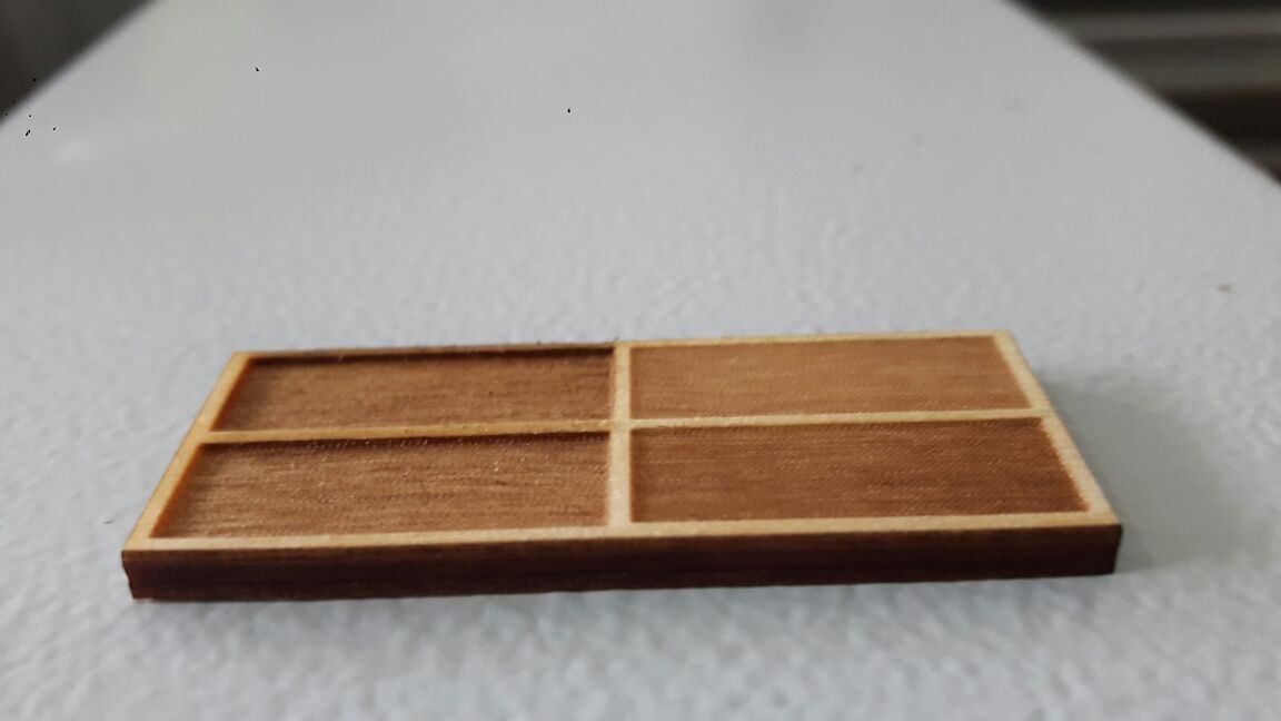
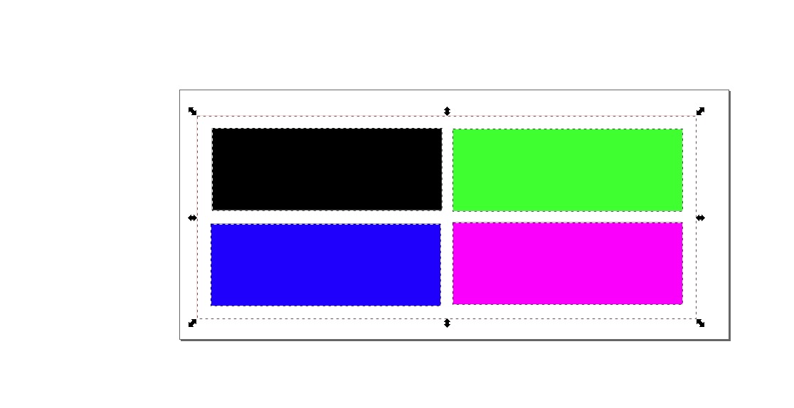
Then we tested with a block with different power settings to engrave. We mapped different colors with different powers and velocity for engraving. Power for Black color was 80, 60 for Blue color, 40 for Green and 20 for Violet. Velocity was fixed as 10 and Frequency was not changed (auto).
Go back HOME