This we are having the continuation of mechanical design. What we are assigned to do is that to document the machine and to document everything.
For our FAB ARM what it is pending is that to automate it.
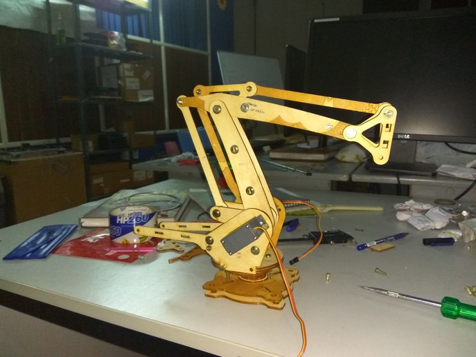
First of all, we assembled our device. For this time we added whole the other components what we left behind over the previous week. Especially the flange shaft to hold up the fab arm.
Then Rahul and Jim started designing a linear rail for giving the horizontal movement of the entire arm. I made a close analysis on it so that I could guide the rail easily which I was assigned to do.
Design of the Linear guide rails
Jim designed a Linear guide rail carriage for our robotic arm, on Fusion 360. The first design was to cut the rails, rollers everything in acryllic, and to have a stepper motor drive integrated to a moving carriage supported on rollers. But later, we found that having this many moving parts is not a very good idea considering the precise movement expected from our machine. So we explored various other ideas, and during one of the weekly lecture sessions Neil mentioned about fabricatable-machines. We explored the gantry design on github, and found that to be simple and robust for our operation.
Making a Linear Guide Rail
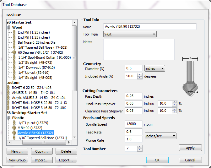
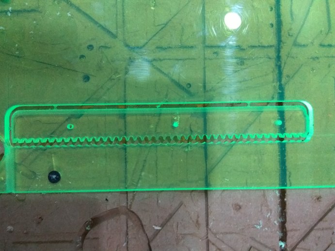
We decided to make the simple gantry mechanism designed by Jens Dyvik which is available in Github . We decided to go with chamfer rails because we don’t have the bird beak bit required to cut v-rails. The next problem we faced was that the availability of materials. As, the High density plastic which we required for cutting the rails is not easily accessible in our region and the cost is significantly higher we choose 6mm acrylic. But, Jens's design was for material thicker than 10mm. Hence we tried with two pieces of acrylic. As that’s a new material to the shopbot in our lab, we test cut the acrylic with different settings based on the original bit settings.
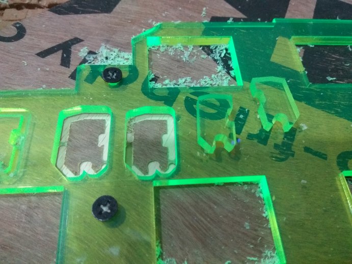
Cutting the Glide block.
The glide block is designed to slide on the chamfer rails. Jens original design requires a material thickness of 10mm or above. We only have 6mm acrylic. Hence we scaled it down to fit the 6mm acrylic.
The main purpose of this test cut was to see if it was possible to make the chamfer rails out of 6mm acrylic. We removed some of the additional features of the rail for simplicity. The next step is to cut the final rail.
Cutting the Pinion
The pinions were cut in the laser because we did not have small enough end mills to make it in shop bot.
But later we dropped down the process with acrylic because Neil advised us not to use the acrylic for such type of works as Acrylic fails by cracking, hence it is not a good material for making something which will be exposed to dynamic loading conditions.
Then we decided to go with PVC foam boards as it seems to be more strong and bendable.
Here also we test cut the material and we studied its properties carefully. The surface finish was good and the material cut through beautifully. The cut was good and the surface finish was not up to the mark.
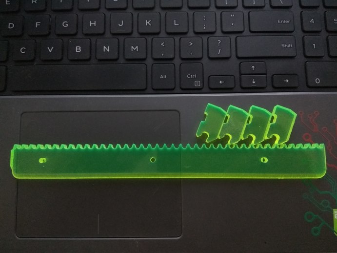
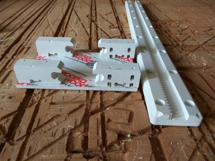
But the cut came pretty good once I gave two cuts, a rough cut and a finish cut at higher speed and lower feed rate. For the rail I used 6mm bit to pocket the area in the middle, before the teeth, where a lot of material has to be removed and Then switched to 3mm bit and cut the teeth profile, pocket for the screws and the final cut lines.
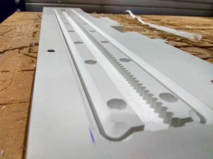
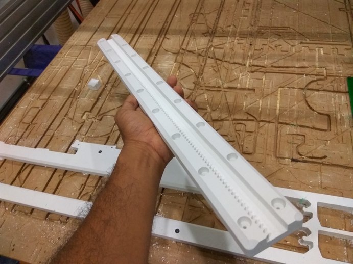
The rail is 60cm long and 18mm thick, The ecoboard is holding it shape nicely, but if you apply pressure at a sharp corner, you will deform the material.
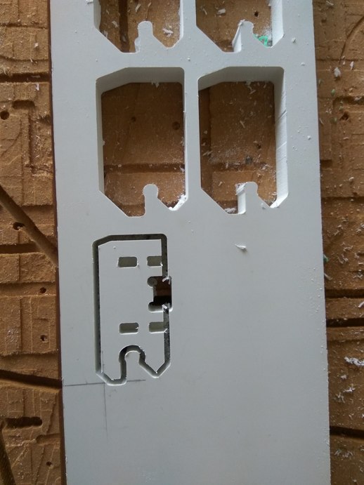
Next is to cut Jens guide block. For that, what it was done that, increased the scale a bit so that it can accommodate the material thickness of 18mm. After cutting out only we realized one critical mistake. Jen's guide blocks were designed for tougher material, we cannot simply replicate them on a weak material like PVC foam.
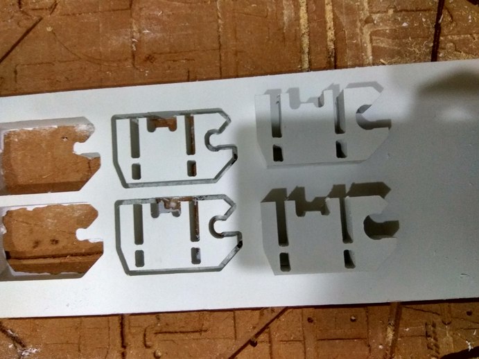
The guide block which we made where really big and also didn’t pocket the interior of the block to its full depth.
After that test fitted the rail guide blocks on the rail. But it seems to be not so good as they were really big and the pockets didn’t came up to the mark. So we cut new pieces.
For this time, the main things that changed was that pushed the inside grooves higher and cut the height of the blocks by 1/3rd its original. Now the blocks were compact and are suitable for a weaker material like PVC foam.
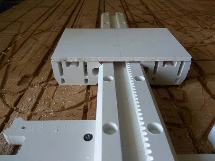
The cut came really well and now the design is ok. Then whole the portions needed for the rail was cut properly. Total four such blocks were cut. Then the guide block was attached to the top plate using M3 screws and nuts. The assembly was done manually, by using a drill to make the holes and inserting the screws in them, tightened by nuts.
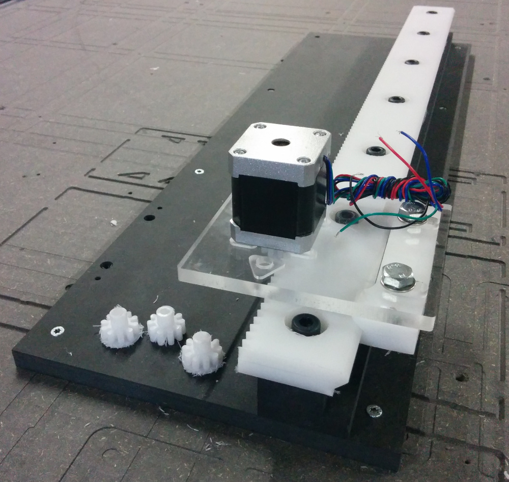
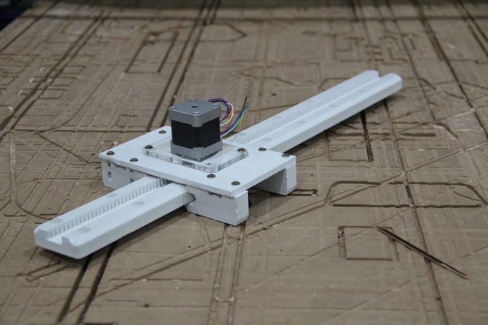
After that what it was done was that, attached the motors into the top plate. The motor plate is attached to the stepper using screws. Then attached the motor along with the motor plate into the top plate of the guide rail.
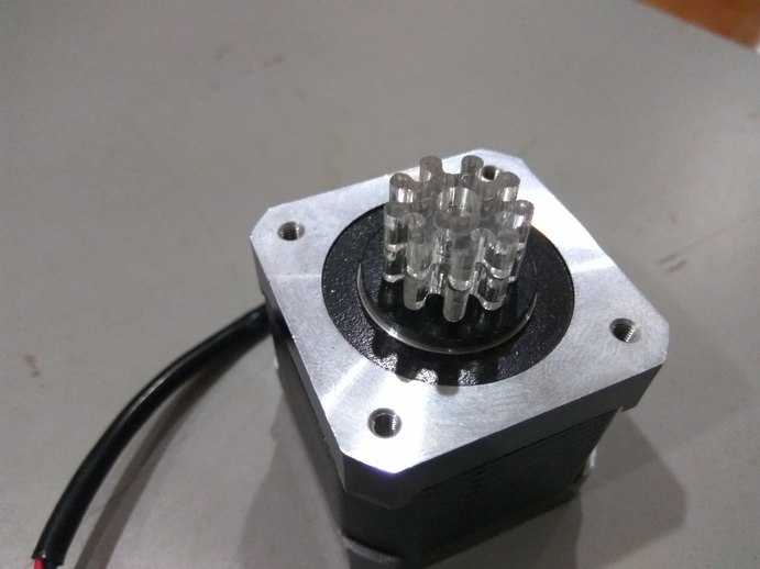
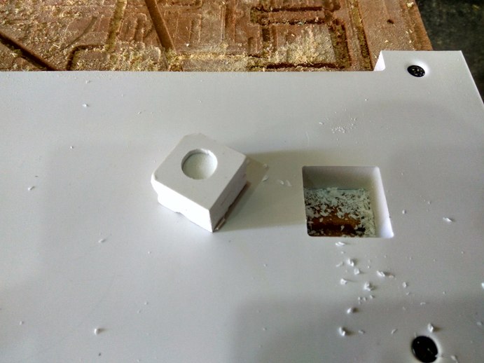
The next is to fix the arm on top of the guide rail. For that wh press fit a small rectangular piece on top of the stepper and attach a base to it. So that the arm can be fixed to the base plate.
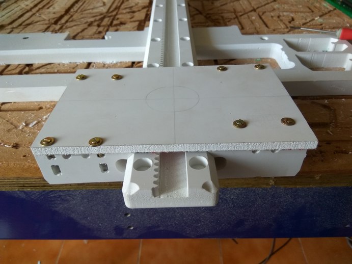
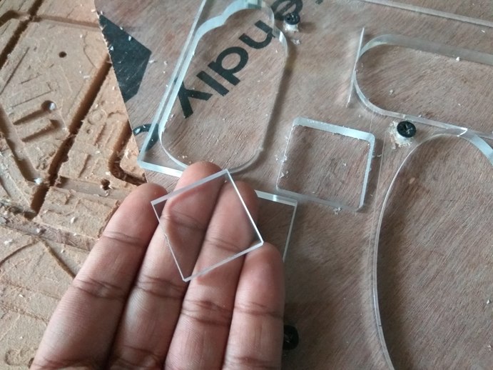
I designed and cut a hollow rectangle to fit on top of the stepper motor. The fit was good and strong, it will support the weight of the arm. Next we had to come up with some way to fix the arm on top of the guide rail. For this I planned to press fit a small rectangular piece on top of the stepper and attach a base to it. So that the arm can be fixed to the base plate.
I designed and cut a hollow rectangle to fit on top of the stepper motor. The fit was good and strong, it will support the weight of the arm. Next we had to come up with some way to fix the arm on top of the guide rail. For this what it is done is that, planned to press fit a small rectangular piece on top of the stepper and attach a base to it, so that the arm can be fixed to the base plate. The design which is provided to cut a hollow rectangle to fit on top of the stepper motor was good and strong, it will support the weight of the arm.
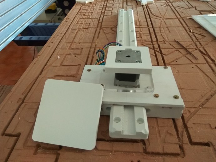
Finally the guide rail is done.
Go back HOME