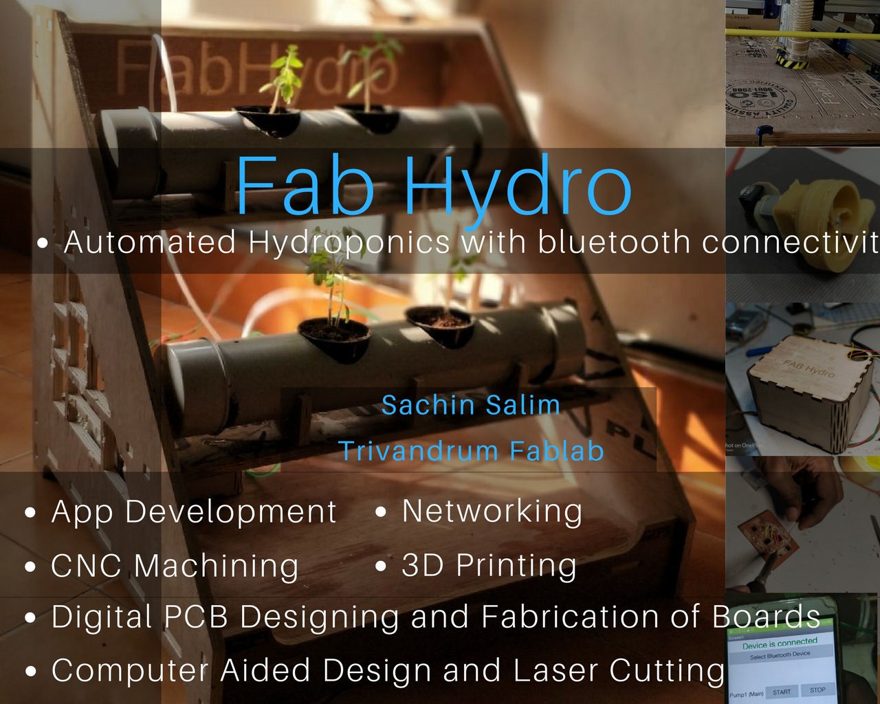
My first project idea was to make a electronics component storage. Later I moved to something related to agriculture as it would relate to my thesis in college. So now my plan was that to make an automatic planter box that works on the basis of humidity sensor. But I found it is omewhat simpler. So choose Hydroponics. Eventhough this system is available in the market, most of them are costly and also large in size. So I decided to make a hydroponics system which is compact , portable and can automatically controlled.
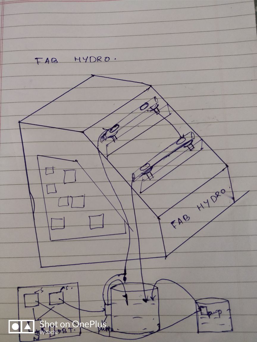
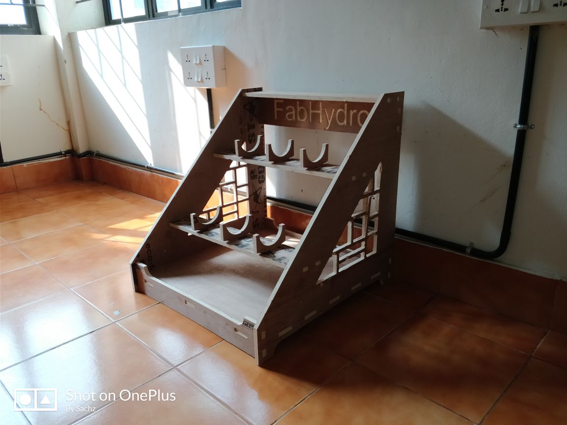
Here I plan to adopt a slanting structure so that both the stand should get light and space equally. From the reservoir water should be pumped to the top pipe. From the outlt of the 1st pipe, its connected to the inlet of the second pipe and then again to the reservoir. This is how I plan to do the case of water cycle. From another tank, nutrients should be pumped to the main reservoir whenever it is needed. Both these pumps should be worked through a mobile app through wifi or Bluetooth. Here by the help of bluetooth module to initiate the master and by I2C as in week 15 to activate the driver boards and hence the pumps.
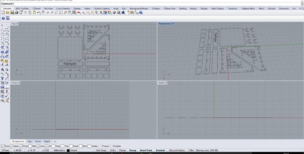
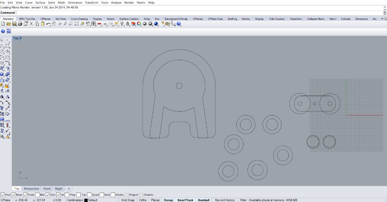
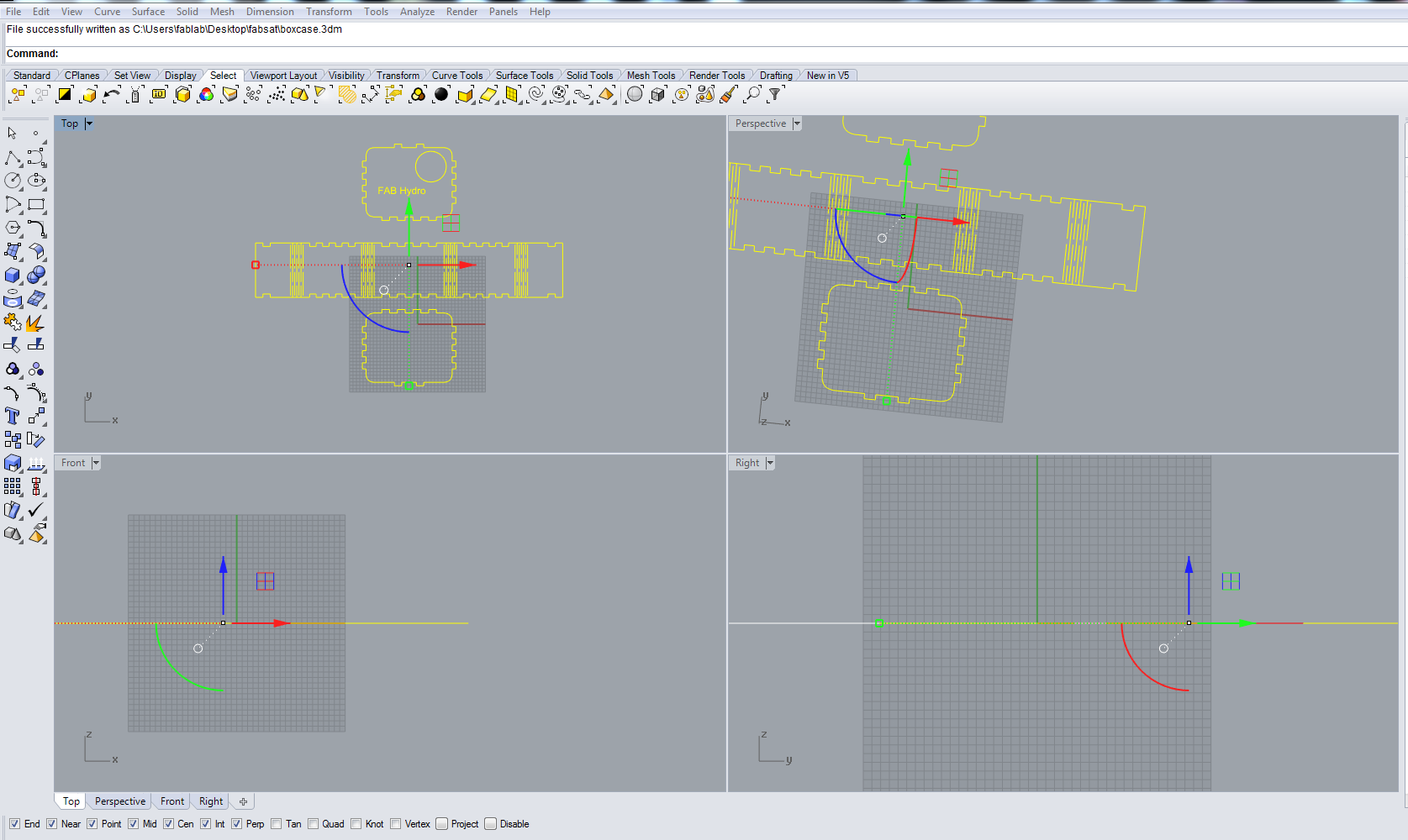
I designed in rhino.
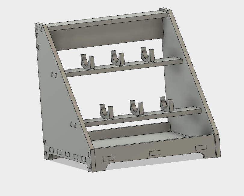
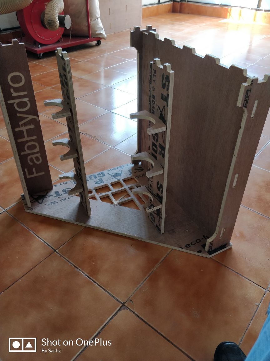
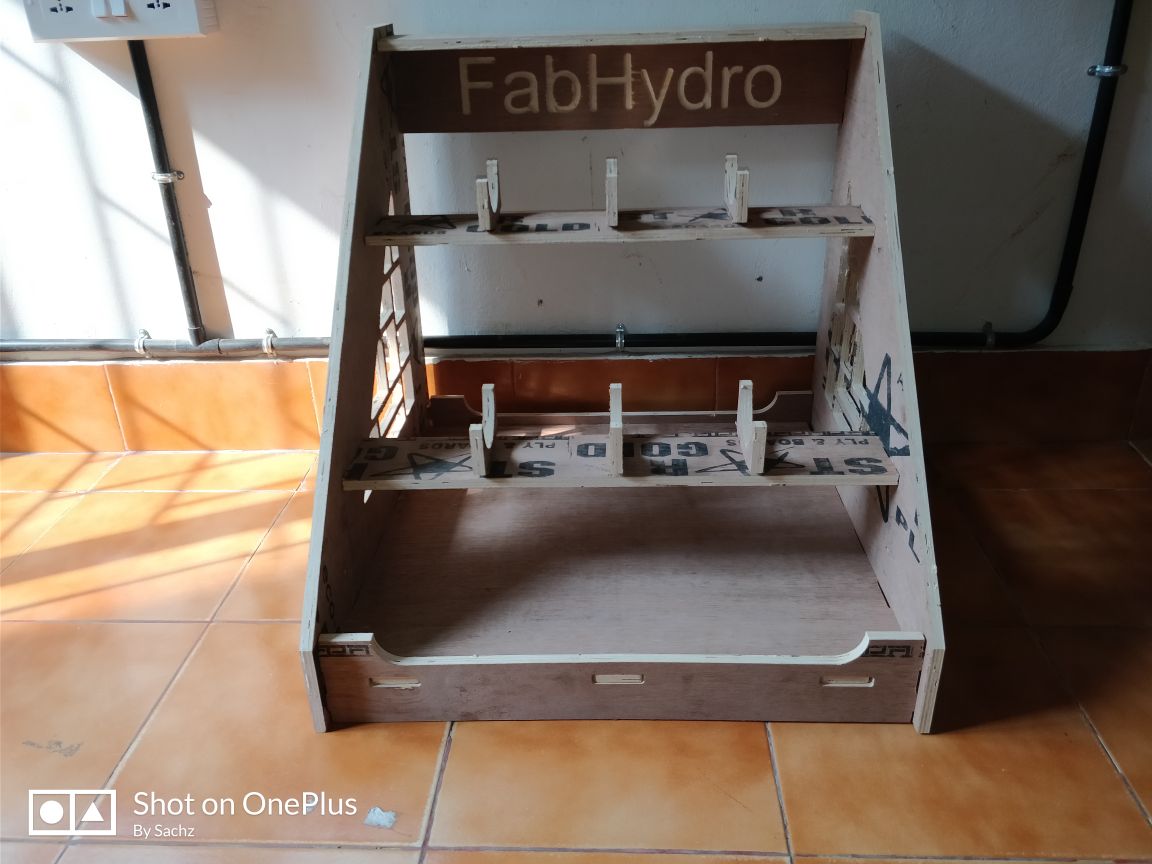
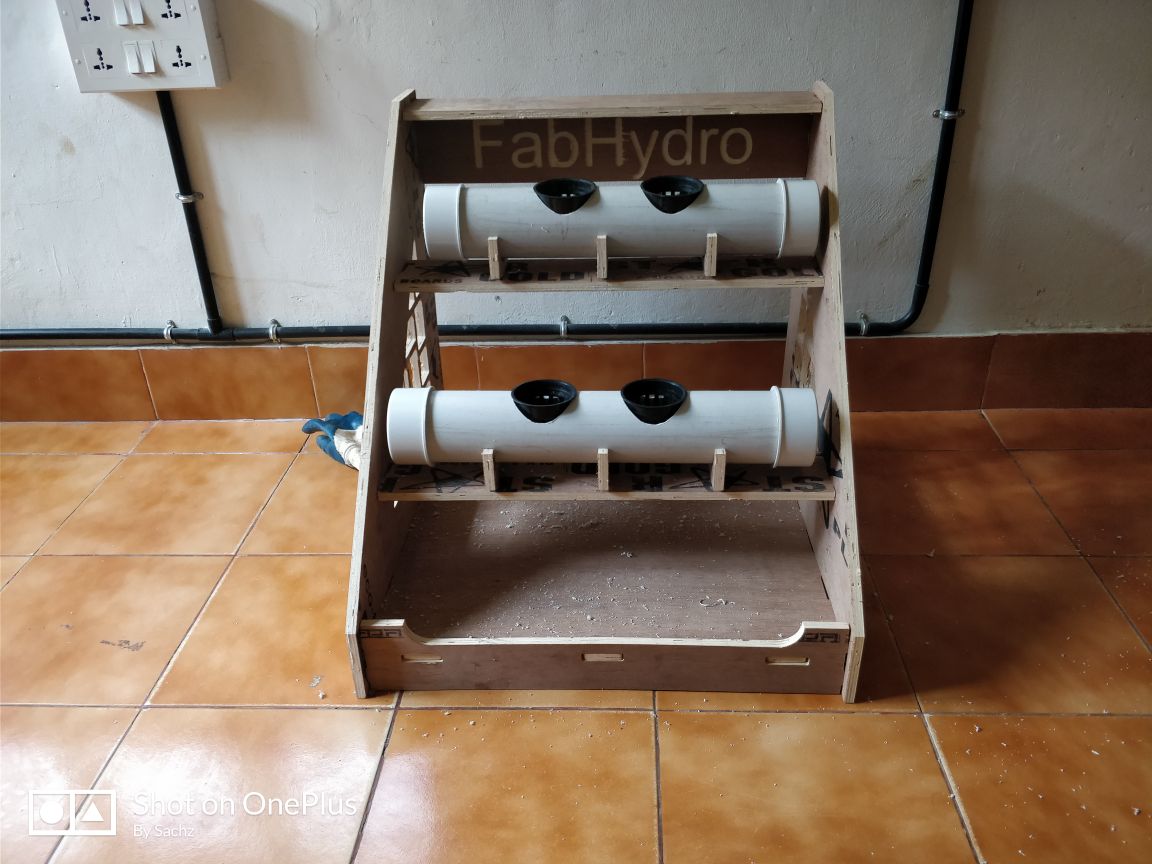
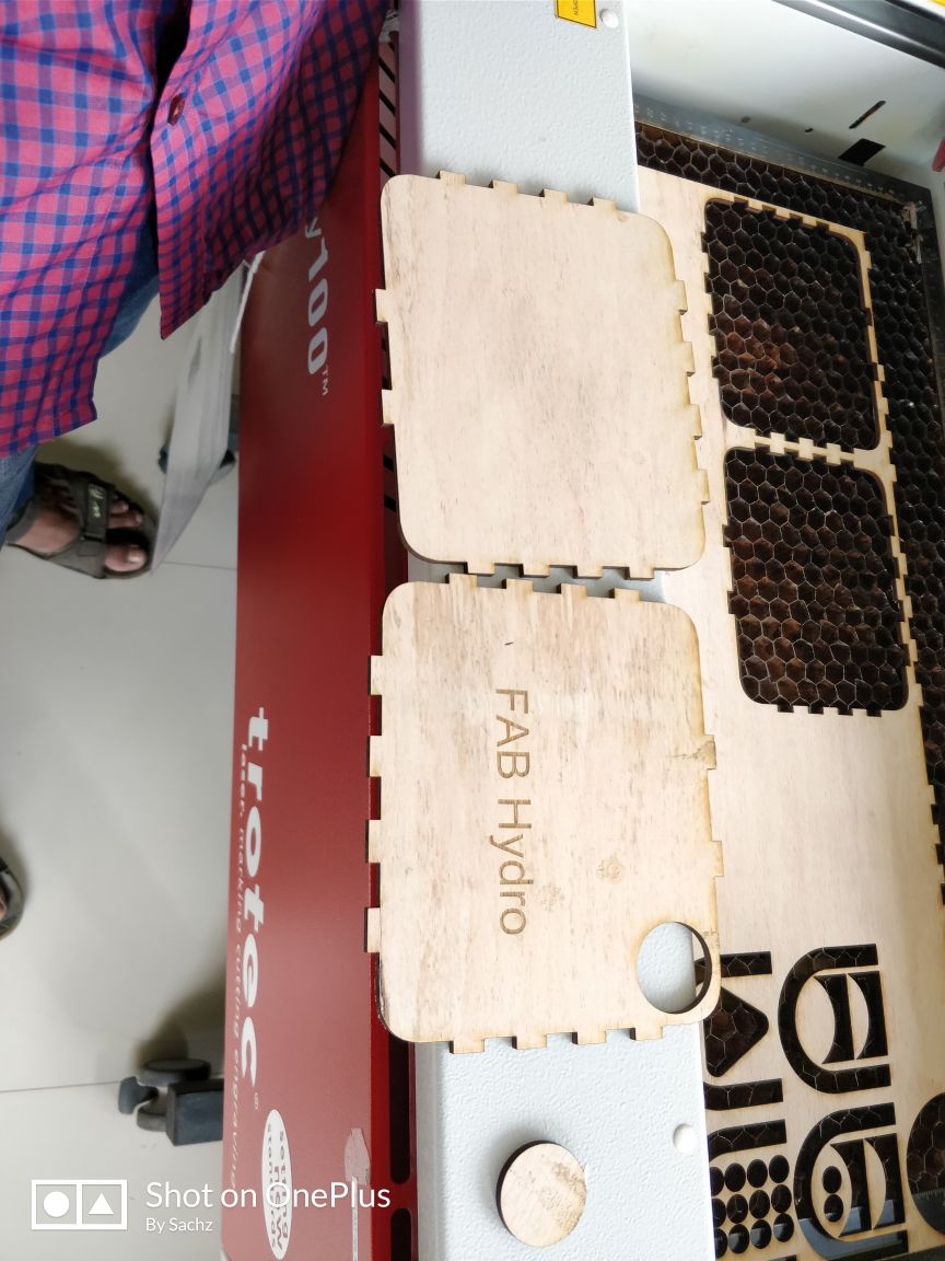
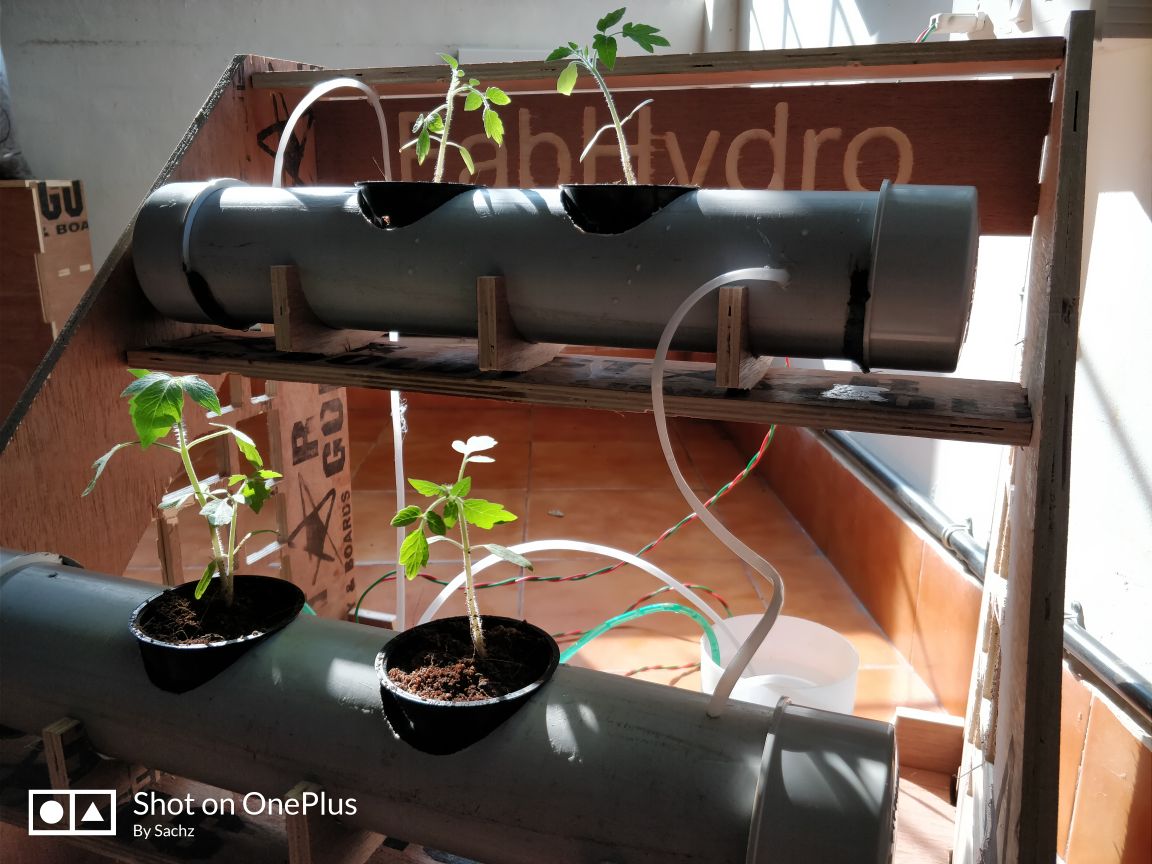
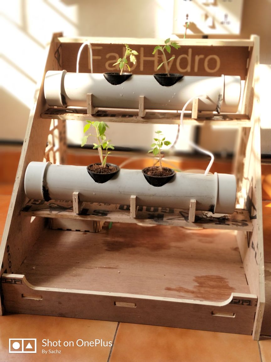
Here what I gave was that a body that would be much helpful to withstand the main portion. So it includes provision for holding pipes and also a platform holding the reservoir and I named it as Fab Hydro.
Next is about the milling the design.
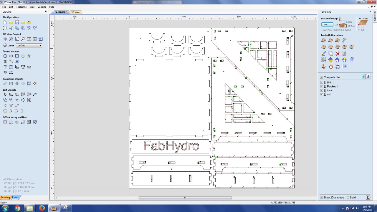
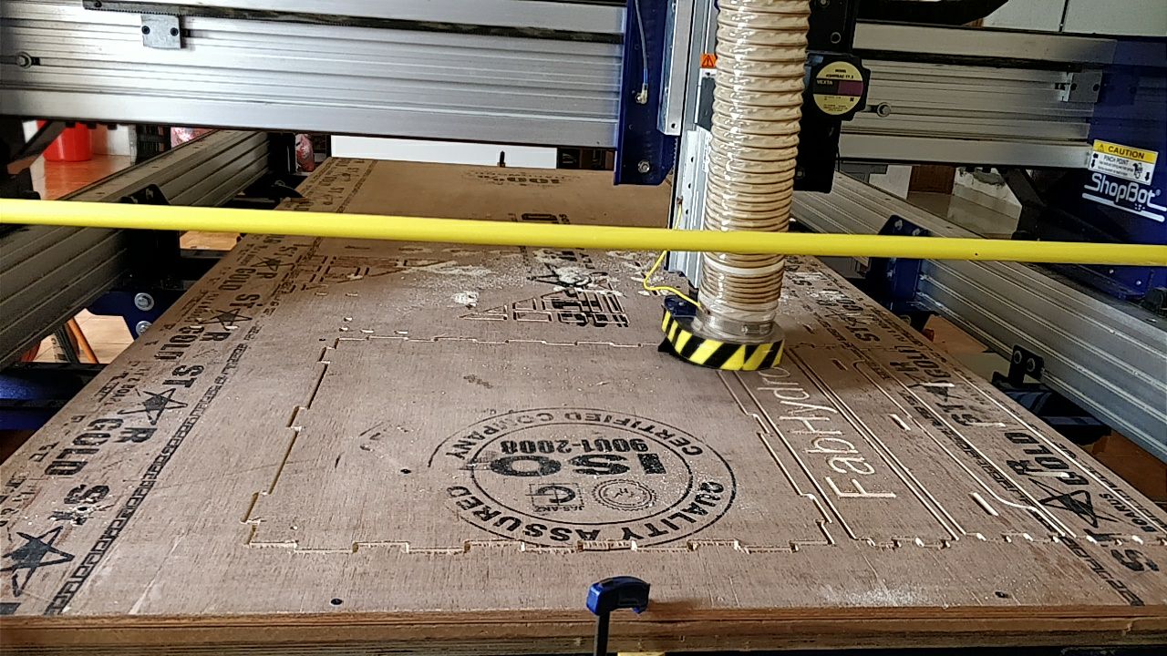
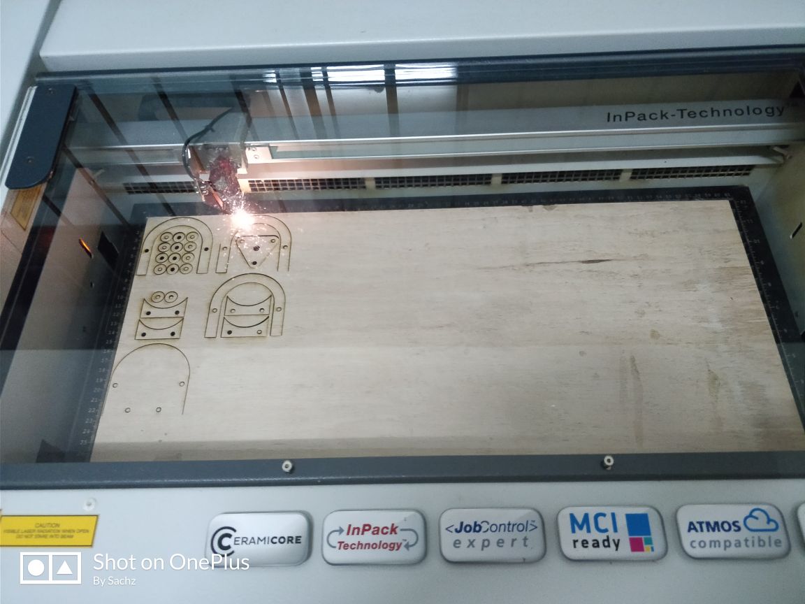
Next I exported my file to .dwg and opened it in VCarve software. Then set the orientation of the design in it. Set the material thickness and fit to material. My material thickness was 18mm. Next is the roughing toolpath creation, In this step we can select the bits we are going to use in my case i have selected a 6mm flat end mill for doing roughing. we can directly change the tool parameters and other stratergies from this window. After setting the parameters we can simulate the profile to know about the time estimate. We can jump to the next step by just clicking the next button also we can go back to a previous step by pressing the previous button.Then I started to mill my structure.
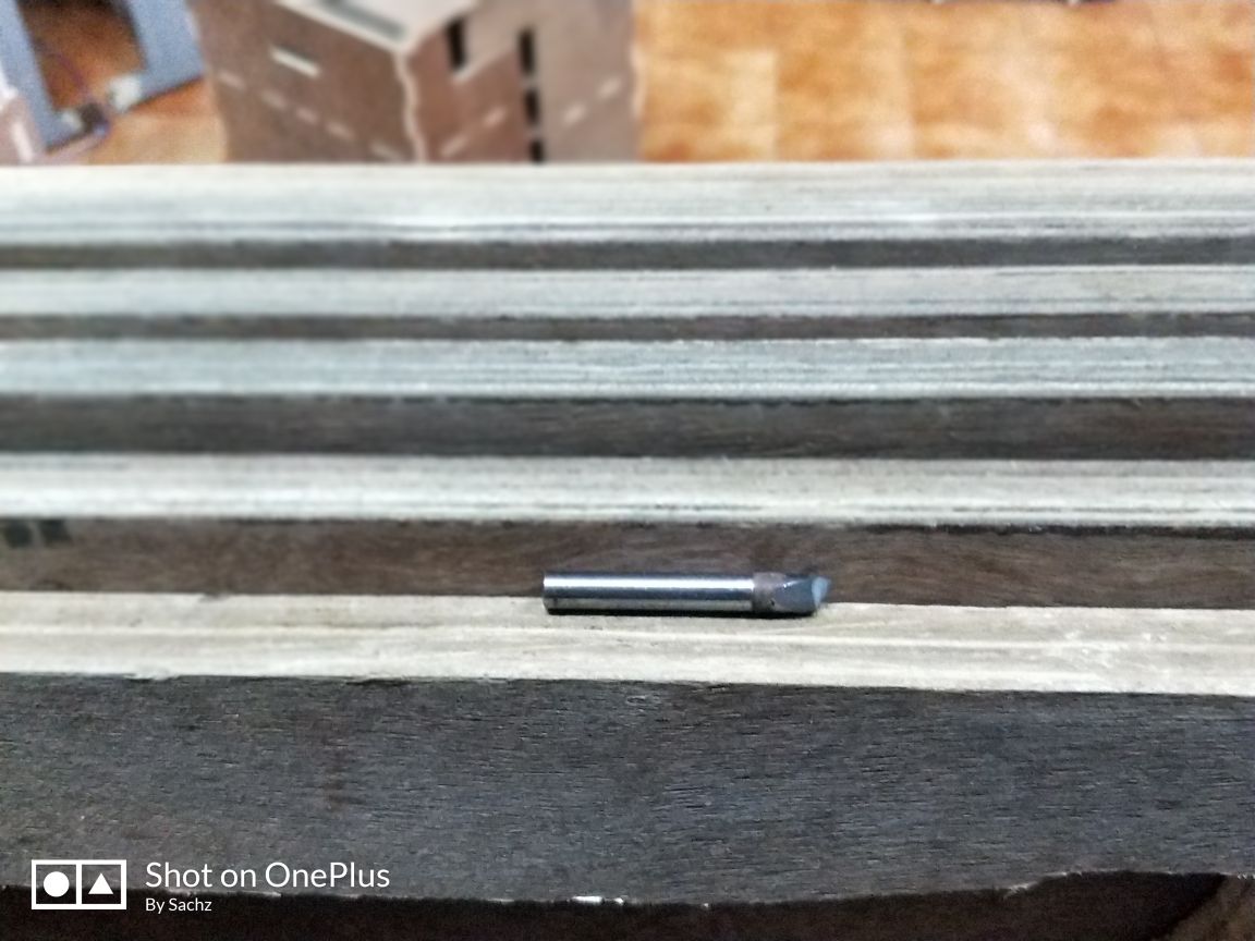
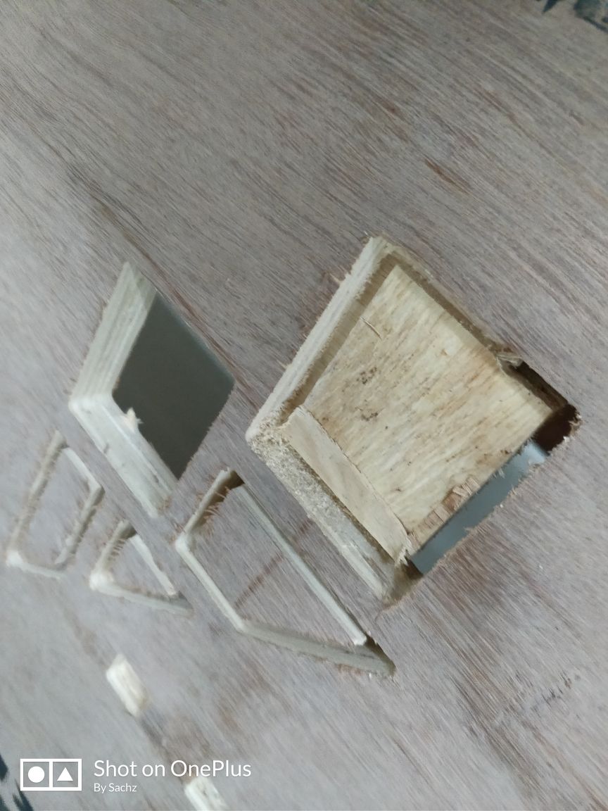
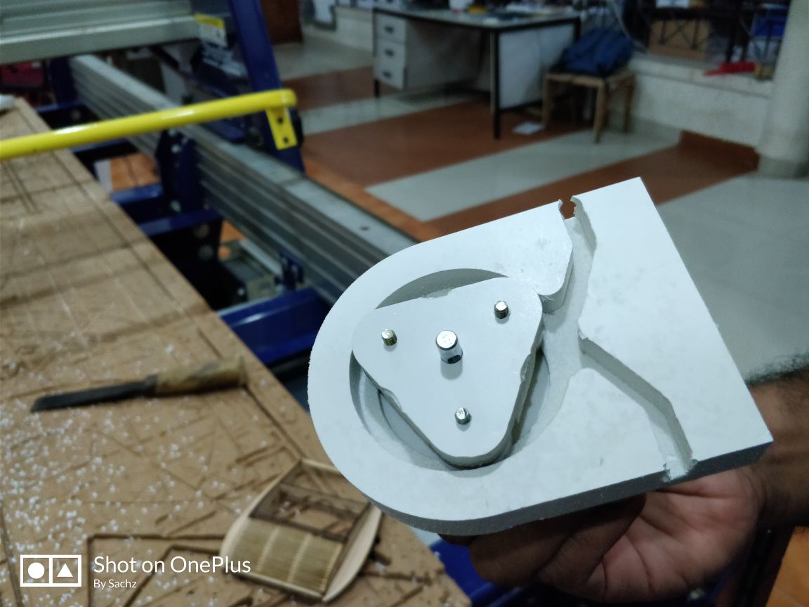
Then I fixed the wood over the machine. I found a partly used plywood in the lab. I checked it found that it would be enough for me to complete the work. But it was 18mm. Eventhough I didn’t that I chose it because I don’t want to waste the others. But unfortunately it was not so good. The wood began to break layer by layer and finally what it happened is that, my bit broke.
The place where wood cracked into layers and that broken layer made my bit to break.
Broken bit
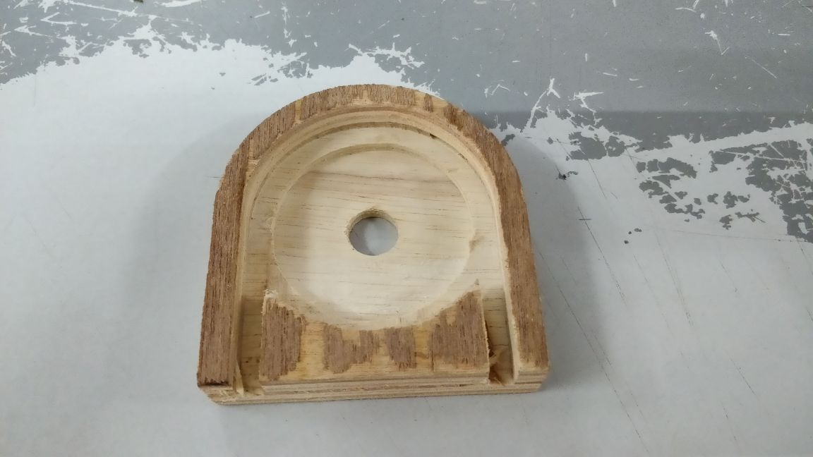
I changed the ply and placed a new wood. This time I choose 12mm plywood. So I changed my design a little bit. As my previous design was based on the 18mm plywood, I need to change according to 12mm. So I changed the design.
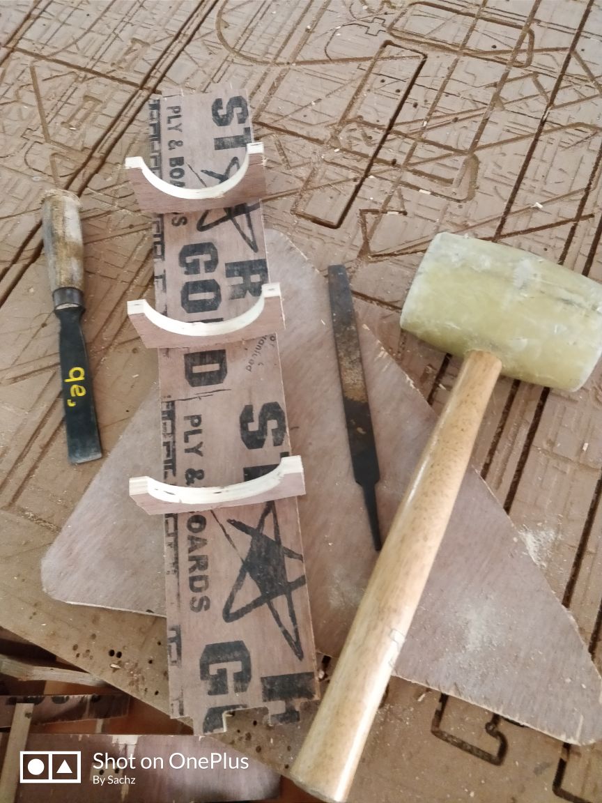
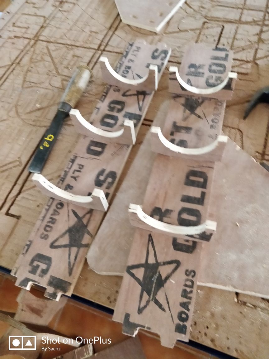
Now my hydroponics parts came ok.
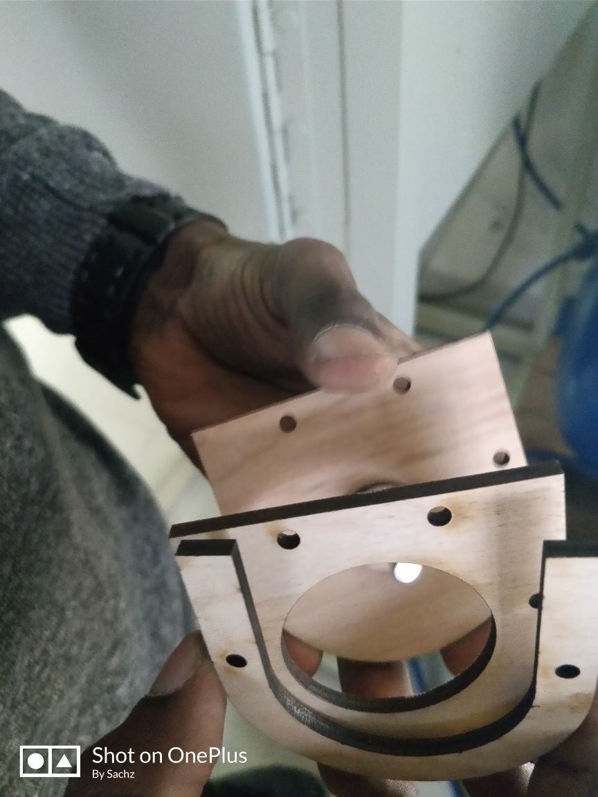
Next I need to join the whole. I it difficulty in some places to fit properly. So what I did was that I cut the corners in a slanting manner using saw and got it clearly it.
I started joing the inner parts
The pipe holding system is ok now.
Then the base
Then joined all the system
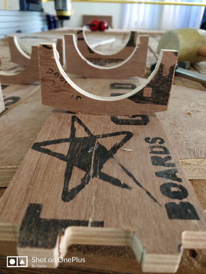
Now it fit properly.
But the thing is that in some places, especially over the places where the pattern designs I gave, some wear and tear was clearly visible due to the bad quality of the wood.
Pipes.
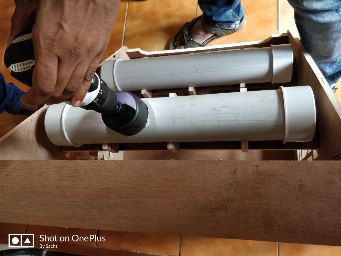
Now its about the water lodging pipes. Im plannimg to to get water from the reservoir to the top pipe, then that water to the lower one and that to the main reservoir. That water should agin be pumped to the upper and the process should complete. So two main pipes of length 5ocms and four endclosers are needed.
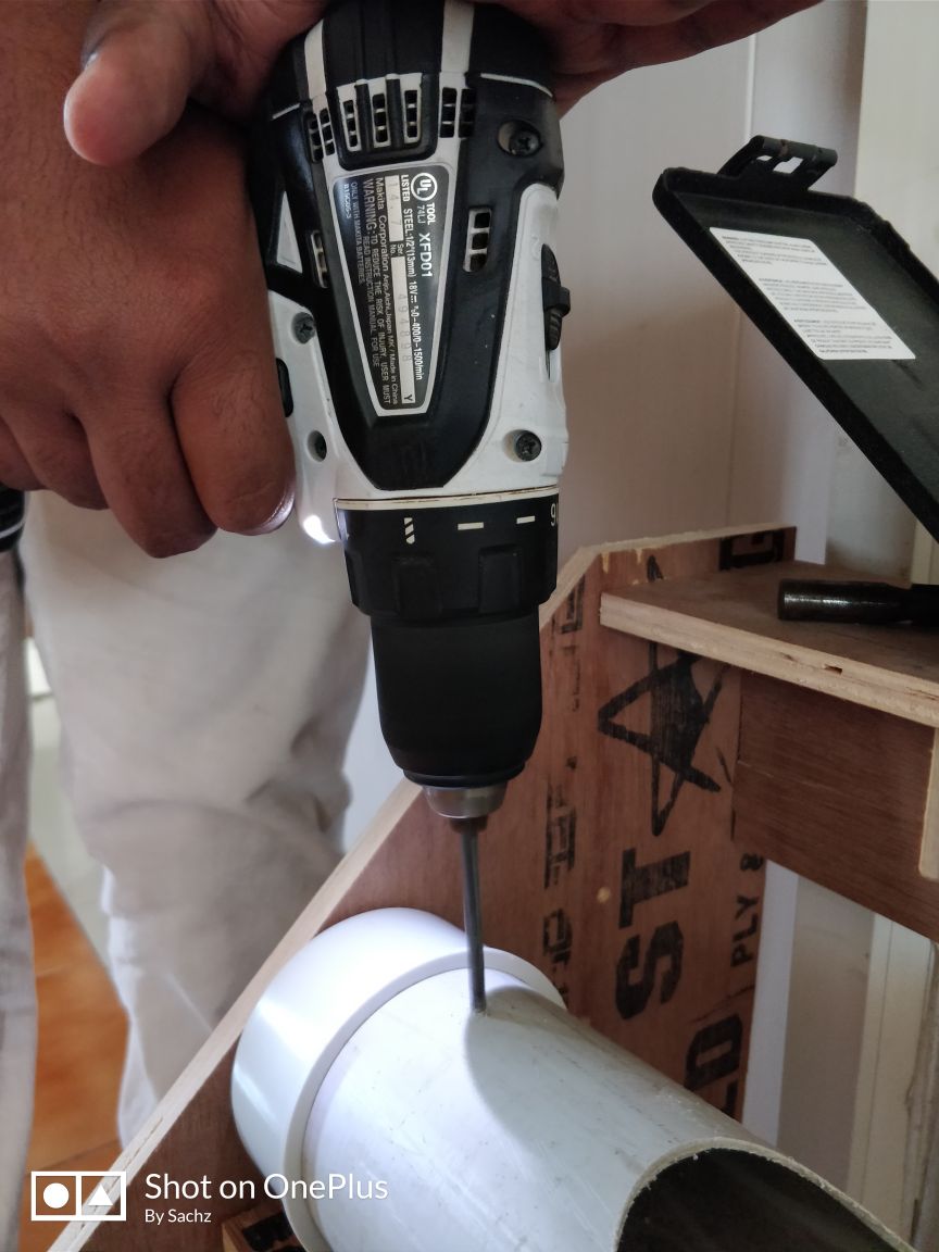
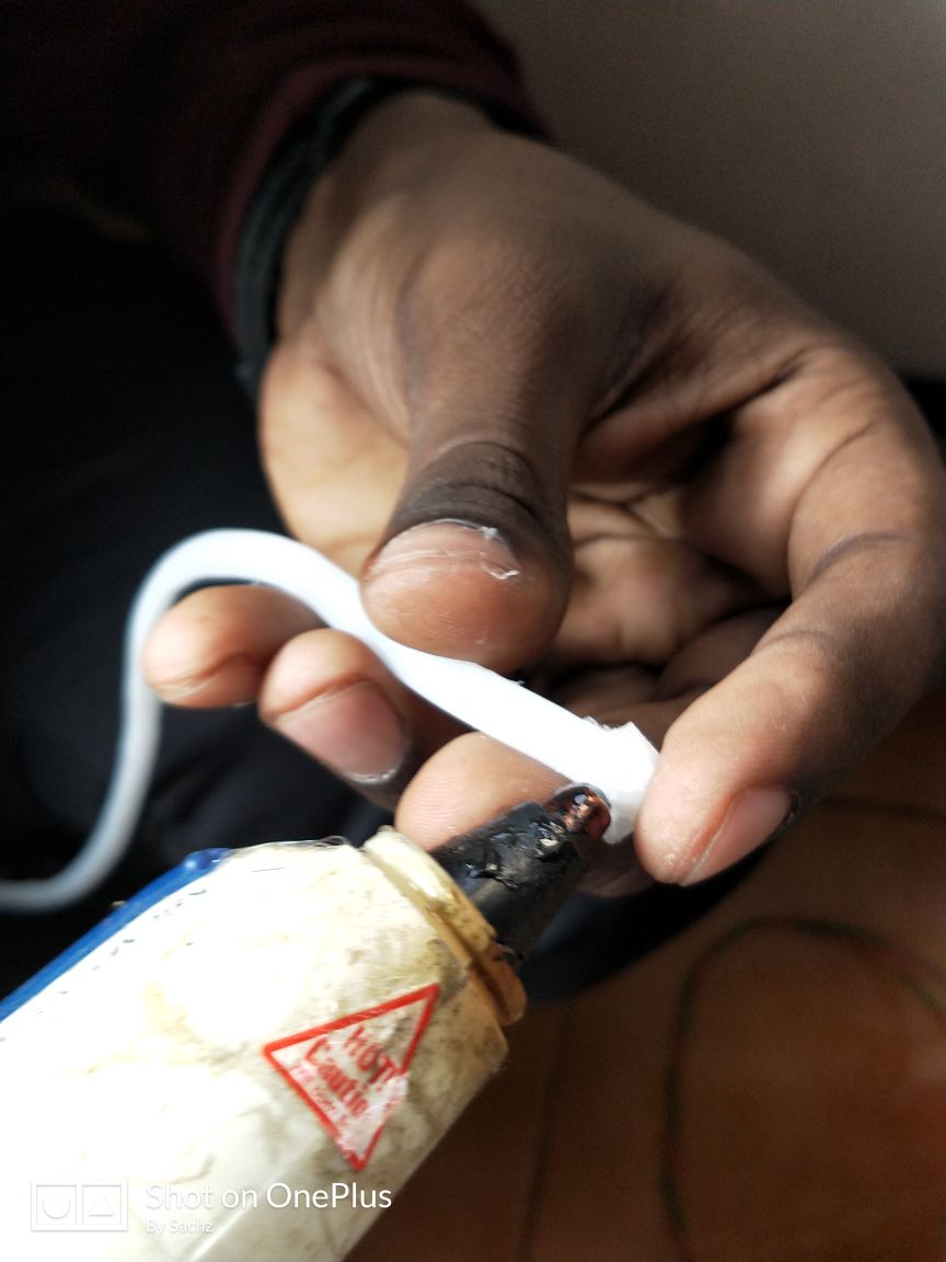
Here I attached hole saw in the drill bit and put hole on the pipe. For leak proof I applied some M Seal.
For leak proof I applied some M Seal.
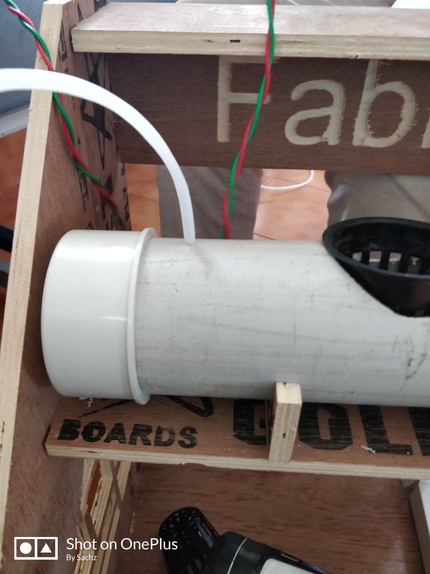
Then the rest remaining is about the silicon tubes.
Before that I think to test whether its leakproof or not. I pour sime wate and find its ok.
After that I made some holes in the tube to insert tubes.
For reservoirs I chose two unused tumblers fro the lab itself.
Next is about the planter pots. I purchased four planter box from outside for planting the plant.
Pump
So now its about the pump. Here first I planned to use a peristaltic pump. A peristaltic pump is a type of positive displacement pump used for pumping a variety of fluids. The fluid is contained within a flexible tube fitted inside a circular pump casing (though linear peristaltic pumps have been made). A rotor with a number of "rollers", "shoes", "wipers", or "lobes" attached to the external circumference of the rotor compresses the flexible tube. As the rotor turns, the part of the tube under compression is pinched closed (or "occludes") thus forcing the fluid to be pumped to move through the tube. Additionally, as the tube opens to its natural state after the passing of the cam ("restitution" or "resilience") fluid flow is induced to the pump. Typically, there will be two or more rollers, or wipers, occluding the tube, trapping between them a body of fluid. The body of fluid is then transported, at ambient pressure, toward the pump outlet. Peristaltic pumps may run continuously, or they may be indexed through partial revolutions to deliver smaller amounts of fluid.
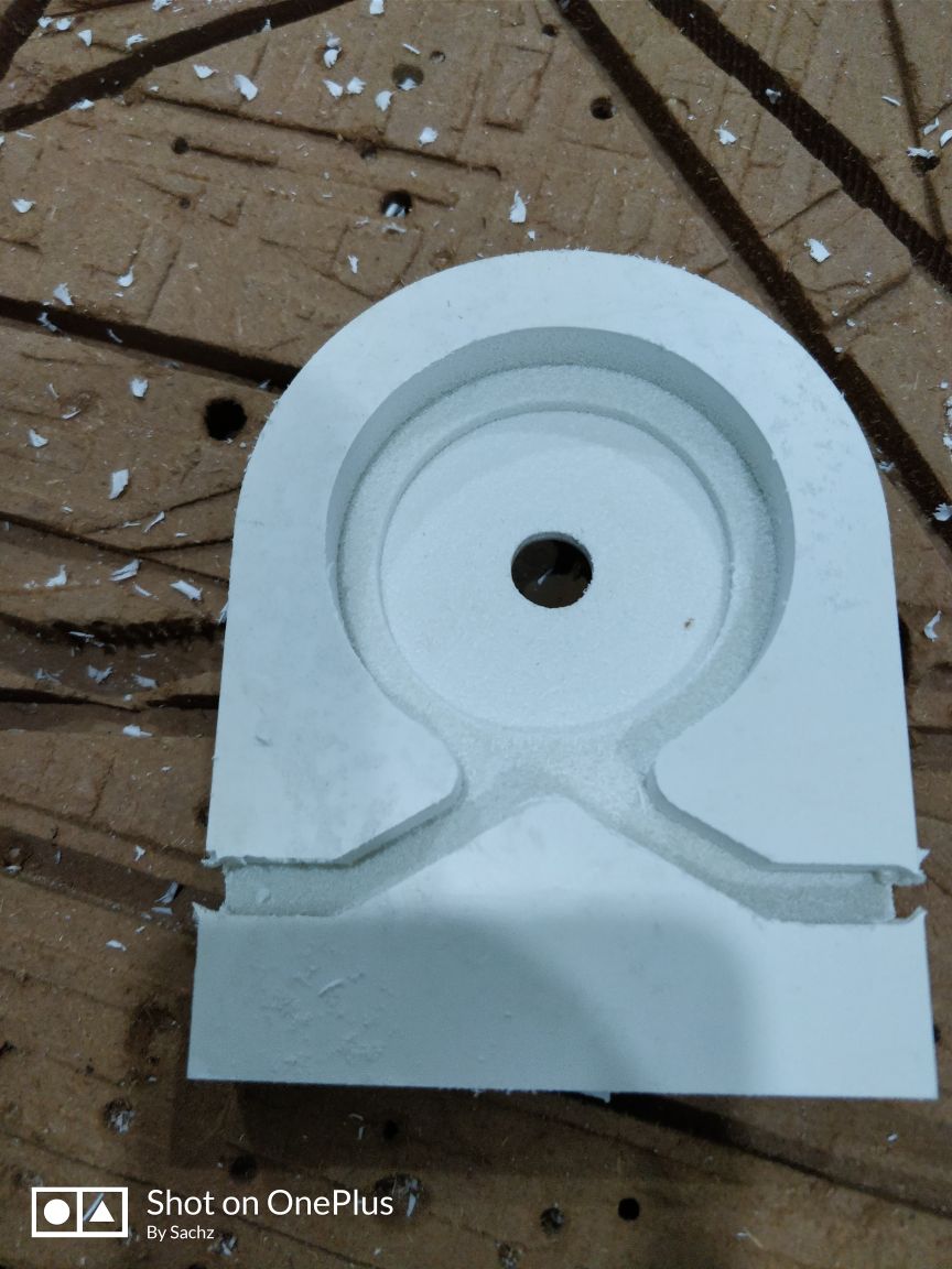
So I decided to make the body of it in PVC board available in our lab.
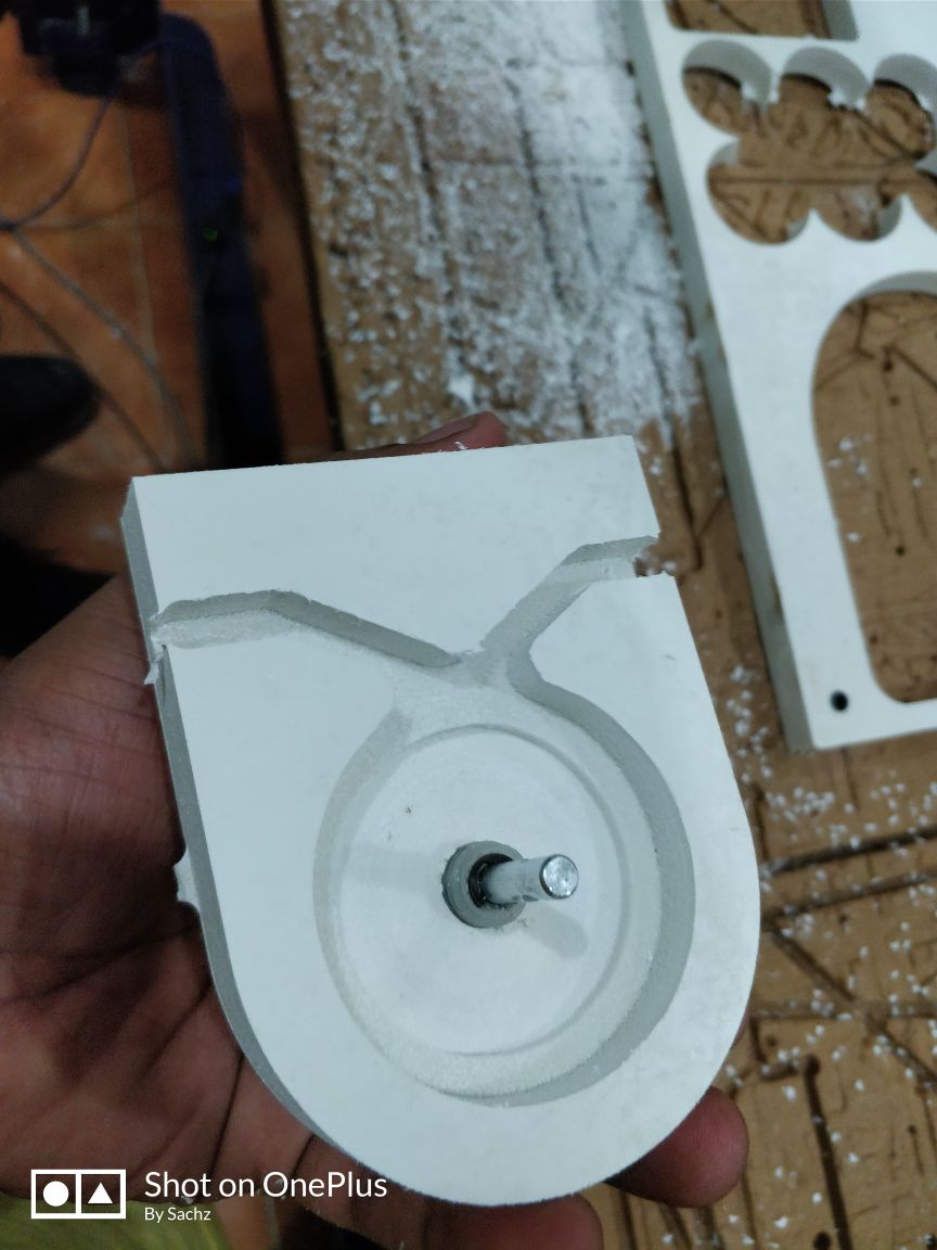
Here I gave a horizontal shaft.
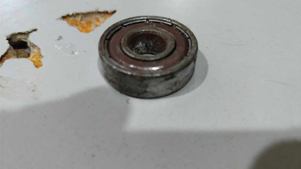
Bearing was available with myfriend
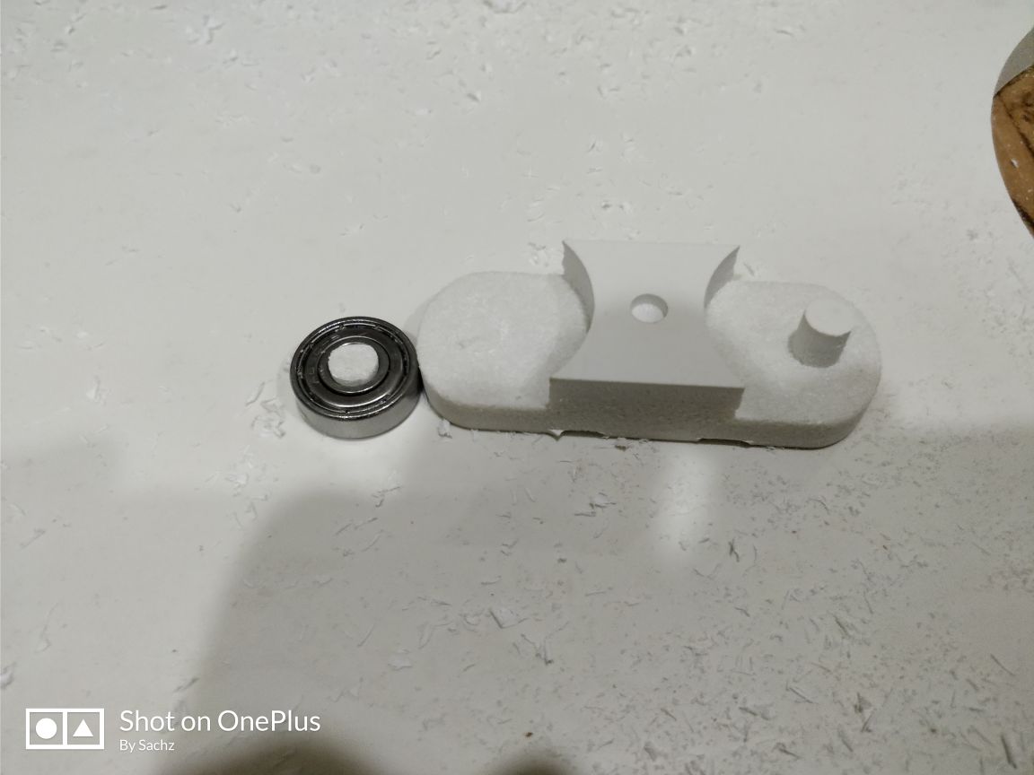
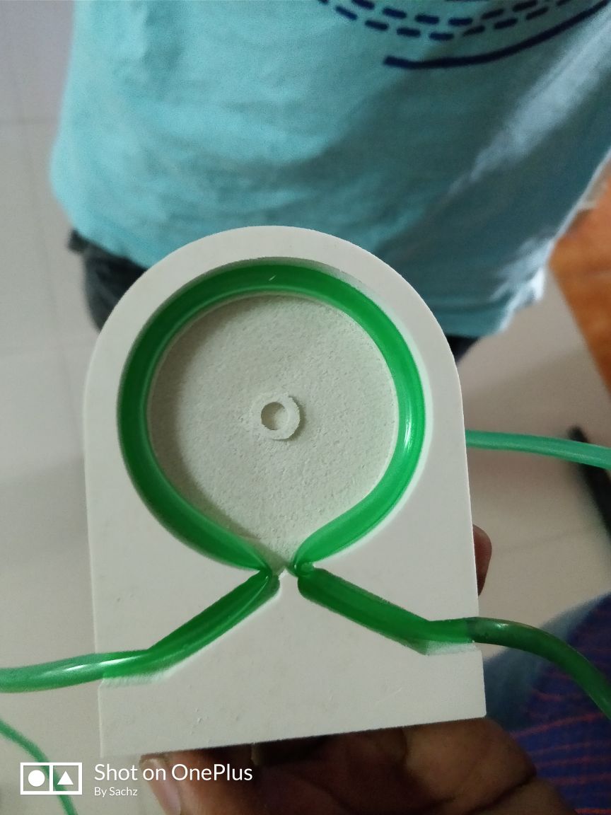
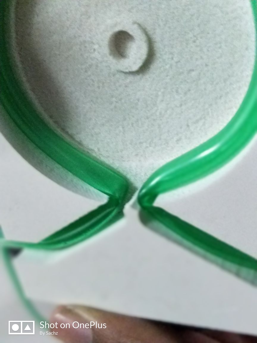
But it was not enough to compress the tube. So I cut a ring shaped foam in the PVC board and put it over the bearing. Now I tested.
Bearing which I used. As the height of it is smaller than the tube when compressed, I decided to put a ring over it.
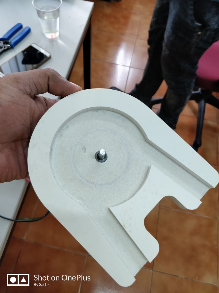
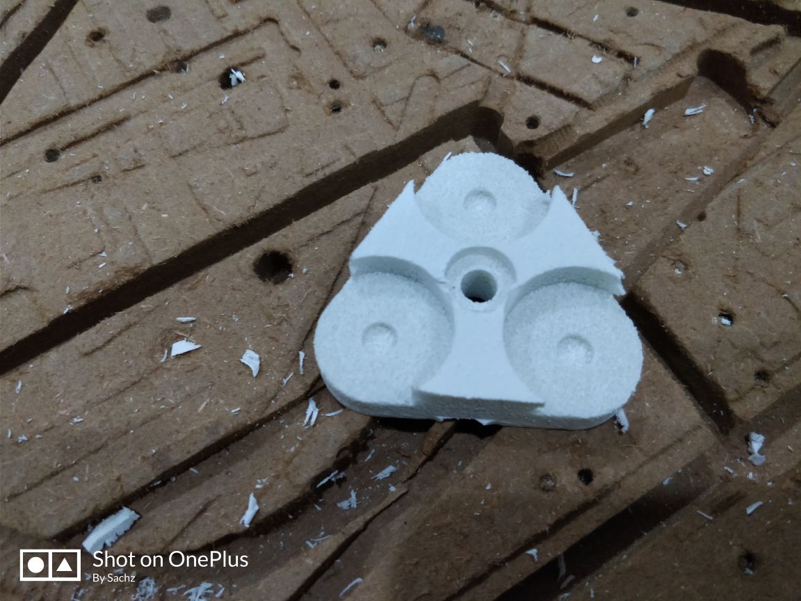
Body of the pump
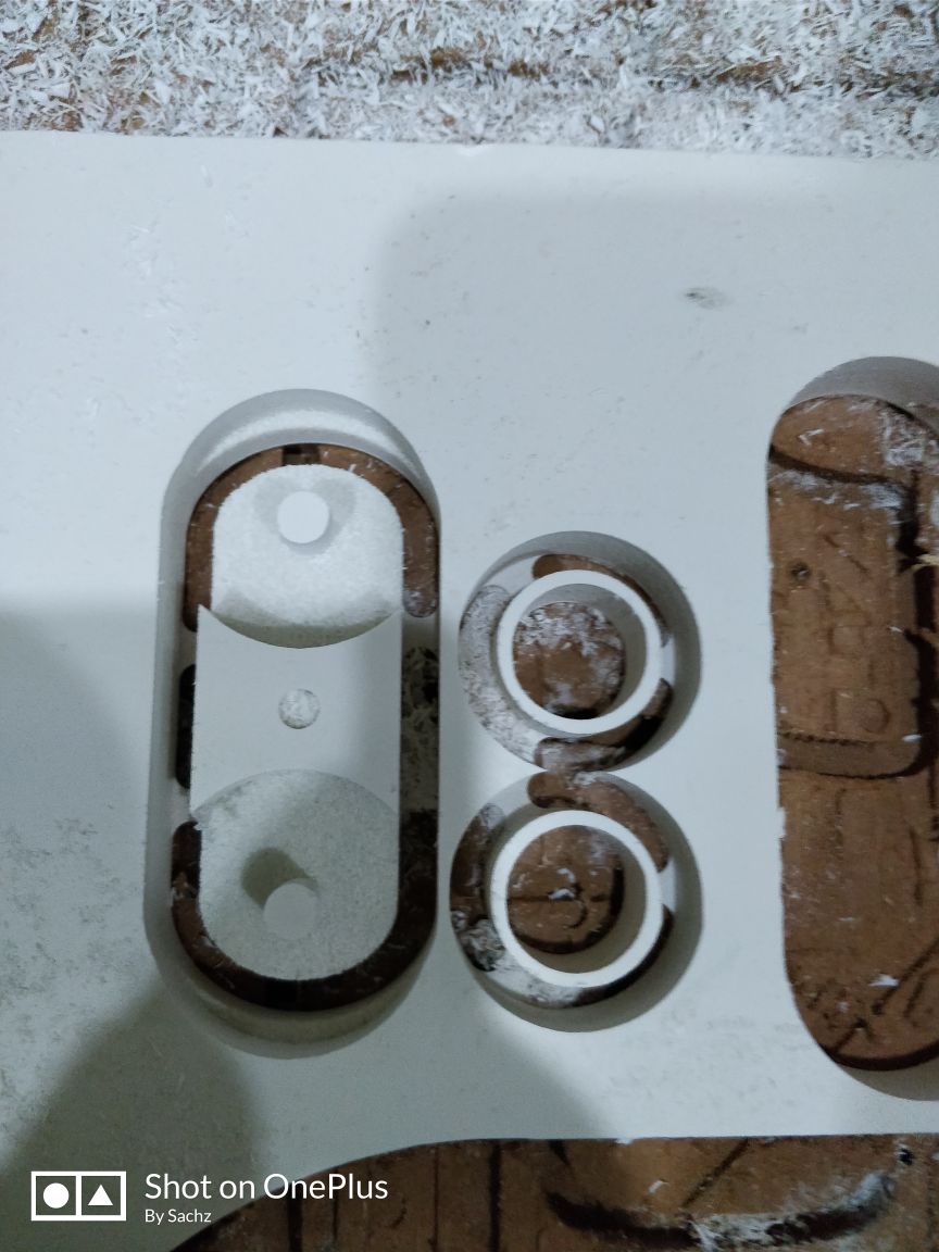
shaft and the rings on which the bearing is placed
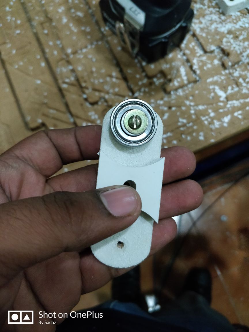
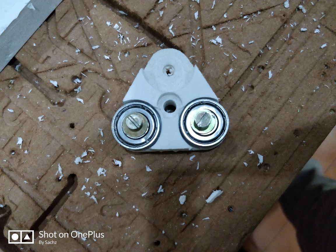
The thing is that, the projection I gave for fixing the bearing was not so strength as it was a fibre board. So in the place of that projection, I gave a hole in which we can screw the bearing.
Screwed bearing
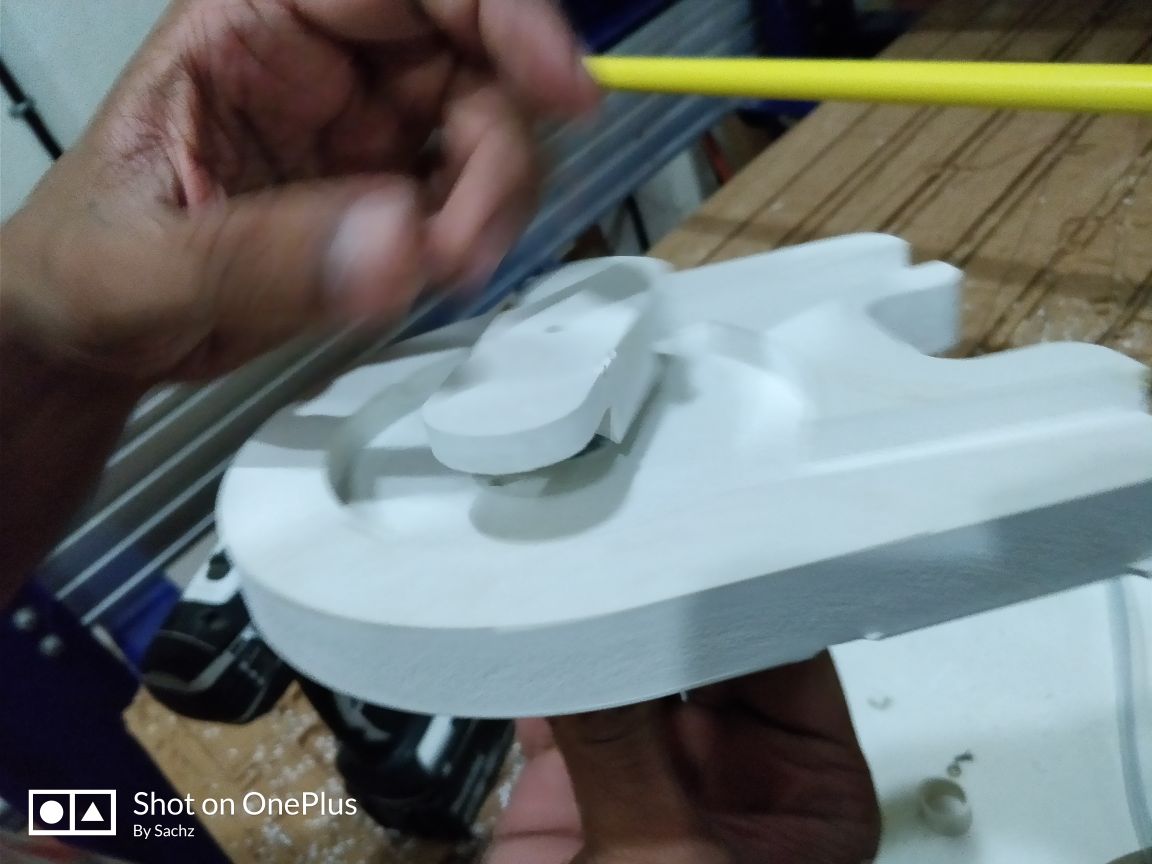
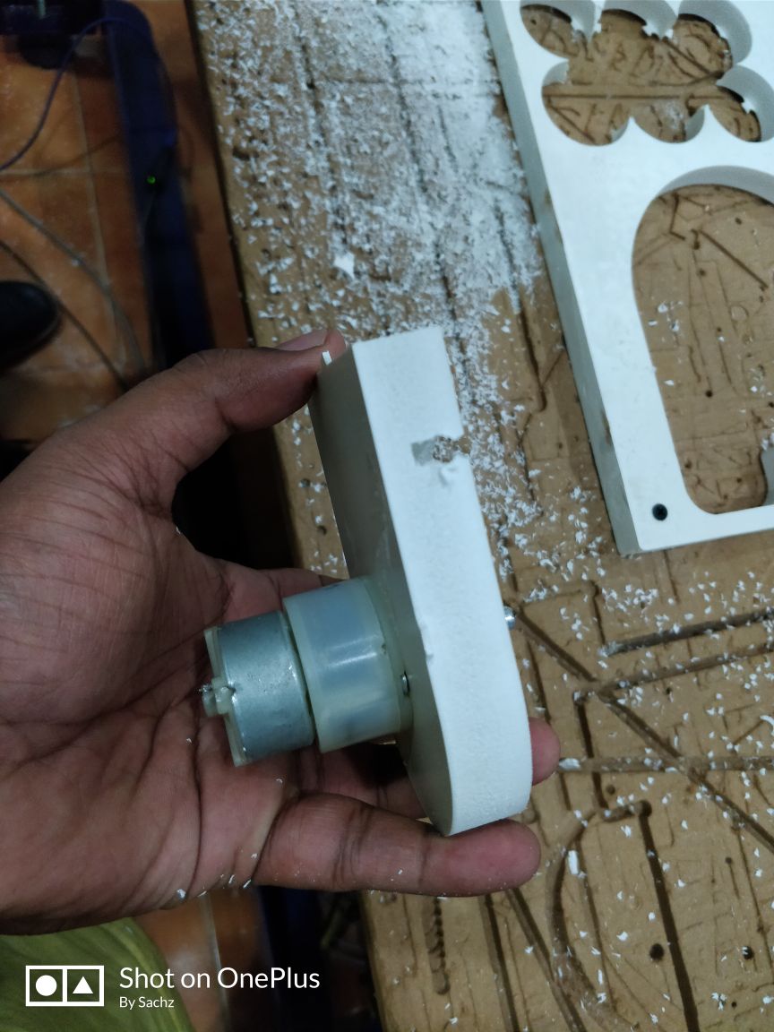
Then I fixed the shaft on the body
After connecting to the motor, I powered it
But water couldn’t get pumped. So I thought it is because of the shaft and also decided to make it much more smaller. Also I thought of correcting th e tolerance level.
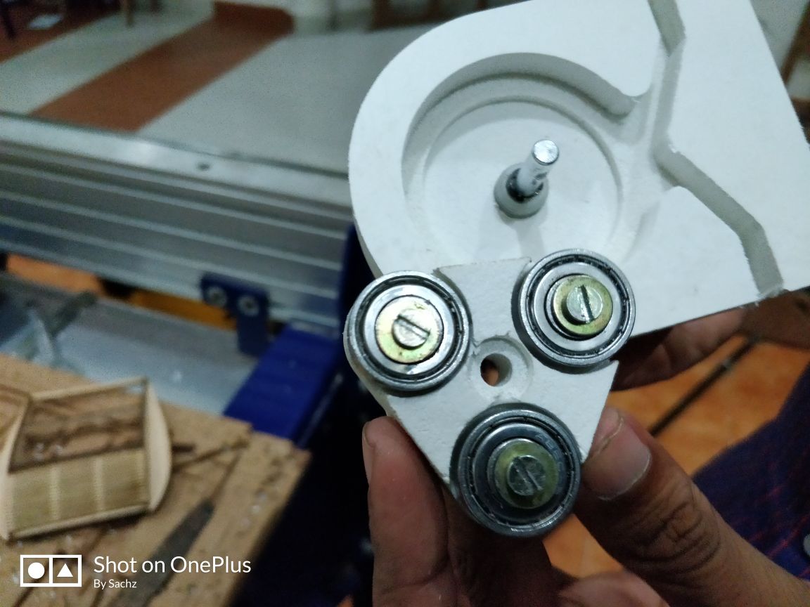
So this time I made a smaller one. I reffered some more videos and decided to provide the inlet and outlet in a locking structure. Also decided to give three bearings.
Pic
Pic
Here what it happened is that by mistake in CNC I gave inside cut which made the inside portion much smaller.
Also the locking structure that I gave made the structure to lock and made the tube to bend. So this made water not to pump.
This was the shaft I made.
The bearing was also connected
Then I connected it with the motor.
But this time what it was hapended is that the silicon wire is getting jammed into the shaft since there is a space which is formed due to projection of thse screw.
So I again made a peristaltic pump rectifying the mistakes that I’ve made. Now gave some projection for the screw revoling.
Here the cut was ok and the space for the screw rotation came properly.
Motor was attached
Its perfectly attached and was tight also
Next is to connect the shaft to the body
Body and the shaft is connected.
But this time also the system was a failure. There is some suction when the motor is ON. But its not up to the mark.
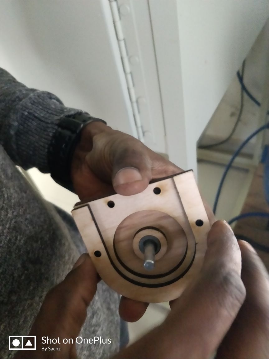
I thought it may be because of the imperfection in spacing. Spacing in the sense that as I used PVC woods, there is a chance to get it compressed. So now I decide to make the pump in wood. So the same design I last adopted was made in wood.
But this time also it didn’t came well. Here the friction was much larger and the motor didnt rotate.
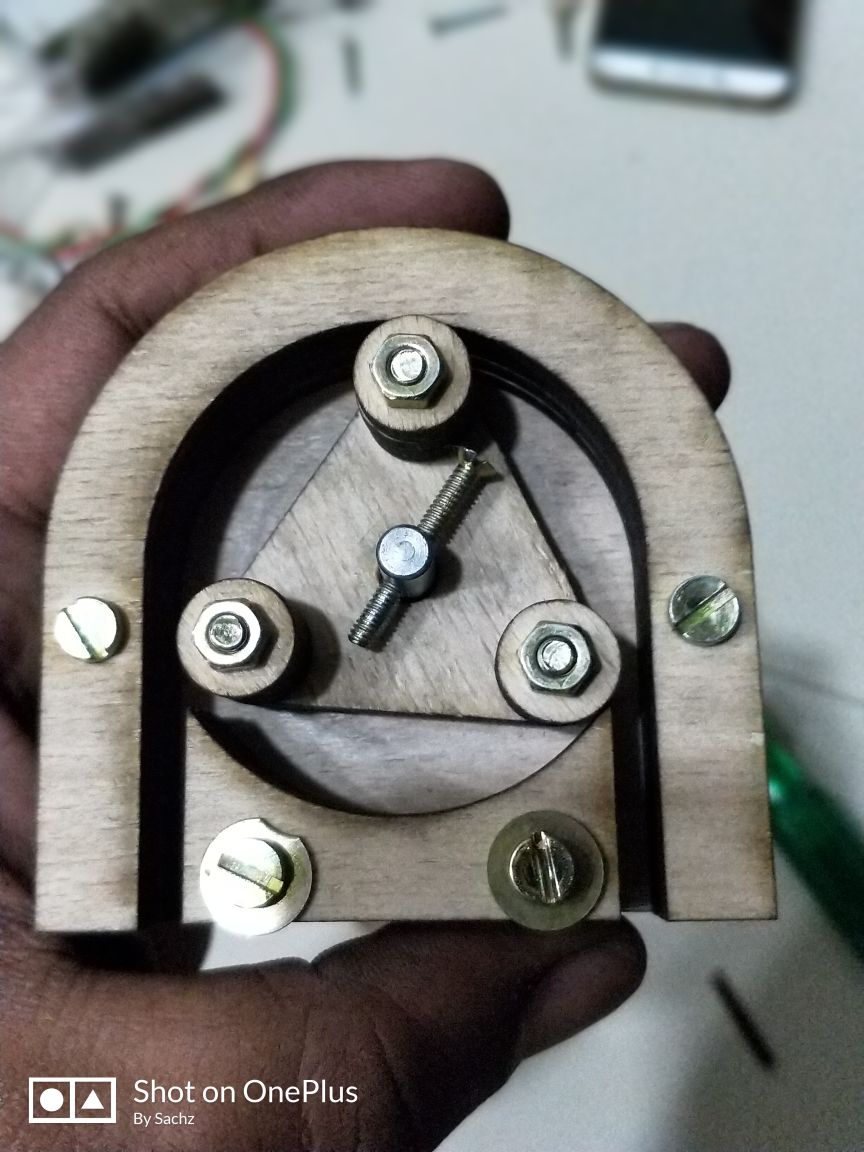
Now I decided to go with laser cut. I laser cut the parts and stacked them and screwed them.
This time what I did was that to give bearing also in wood.
I laser cut its parts
Different parts of the pump was obtained.
Next is to stack the parts together
This time for bearings what I did was that made several small cicles in wood and stacked them together.
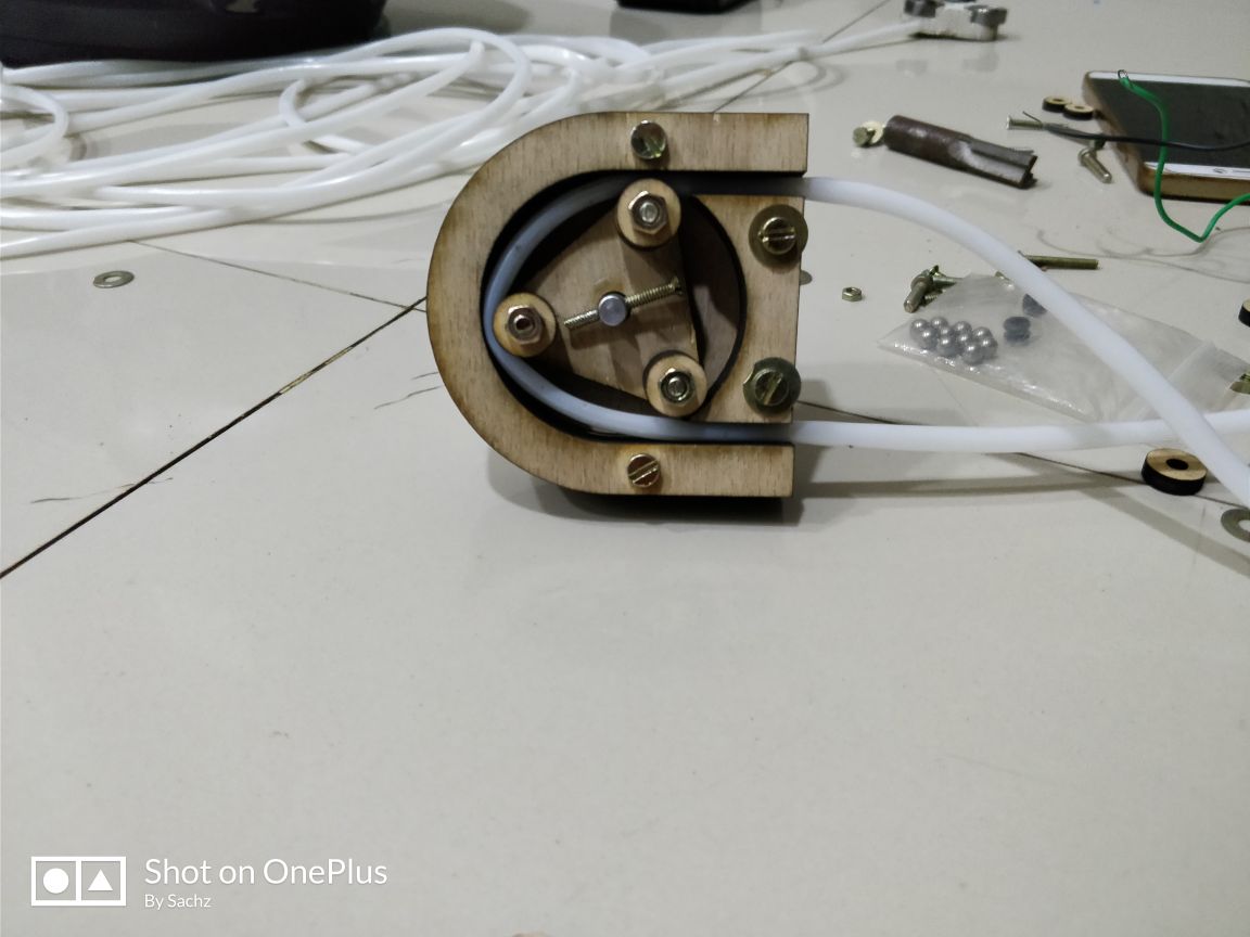
Tube is connected and to make sure the system wont dismantle tightened it with a screw.
But finally it was also got failed. Referring to the other peristaltic pumps I could see that the design was not so different from those which are working perfectly alright. Finally I decided to go with some other pumps. So I decided to go with some other pumps and cose centrifugal pump
The problem is that it doesn’t pumps to a larger height and it should be get submerged into the reservoir.
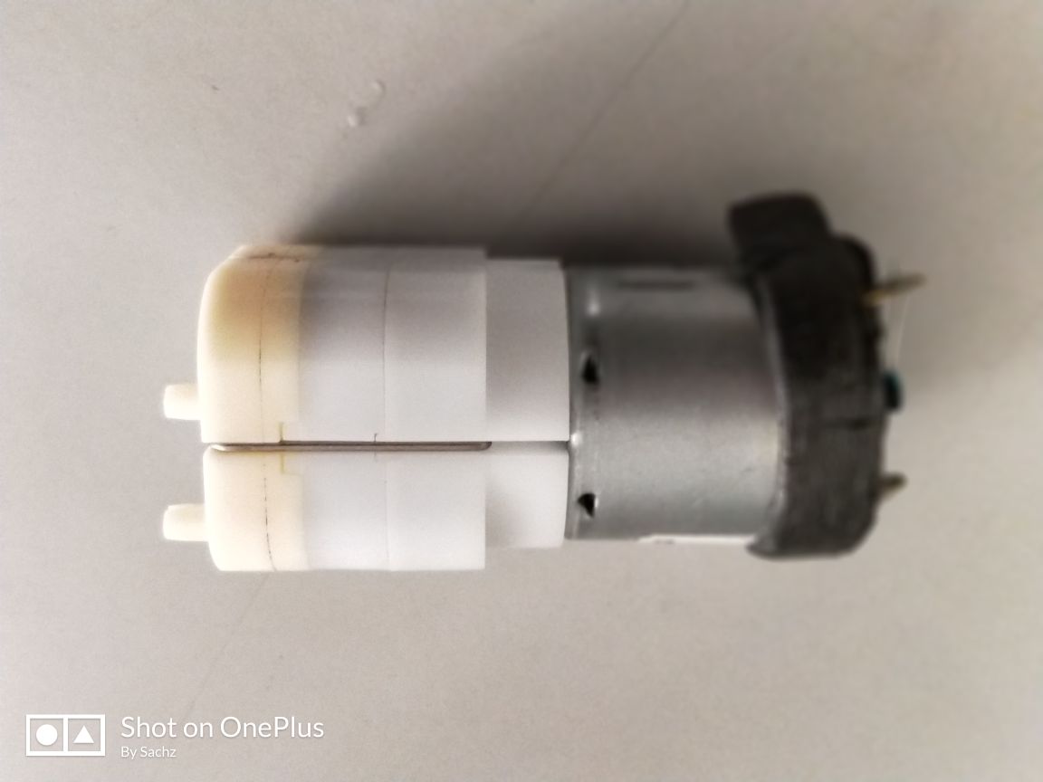
I got a diaphragm pump from my friend Sreejith and I tested it.
Diaphragm Pump
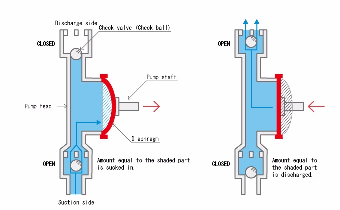
A diaphragm pump is a positive displacement pump that uses a combination of reciprocating action and either a flapper valve or a ball valve to transfer liquids. This pump is sometimes referred to as a membrane pump. Diaphragm pumps are self priming and are ideal for viscous liquids. Most models are available in electric, engine, manual, air operated or hydraulic configurations.
Schematic of the diaphragm pump
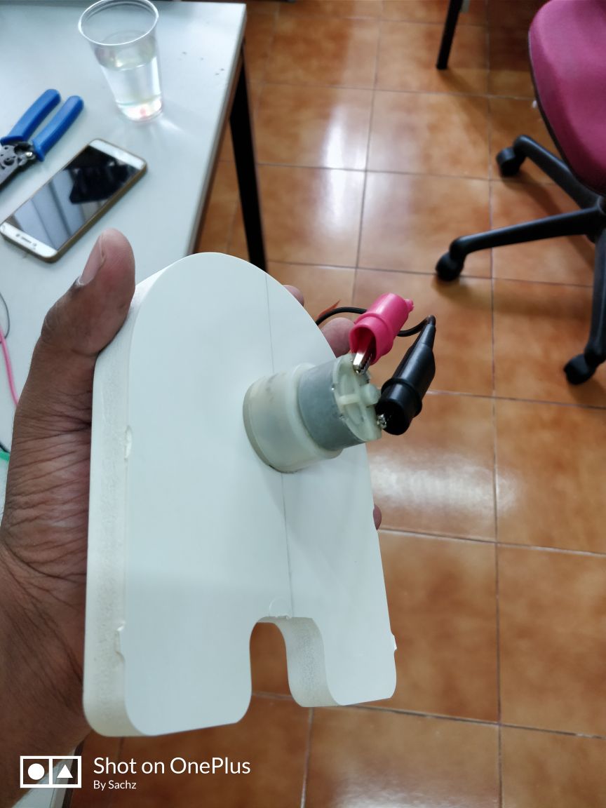
Diaphragm pump which I'm using
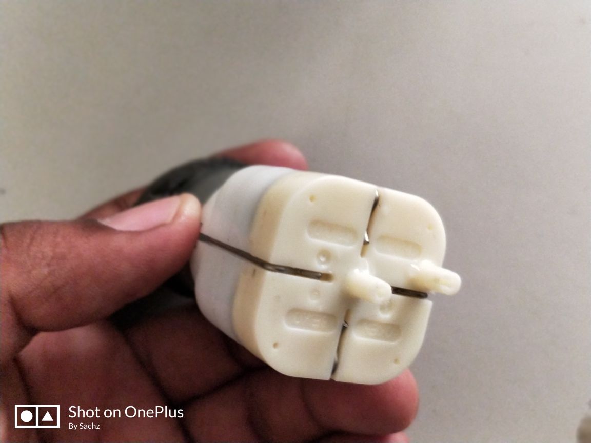
Inlet and Outlet of the pump. Here middile portion shows the inlet and the other shows outlet.
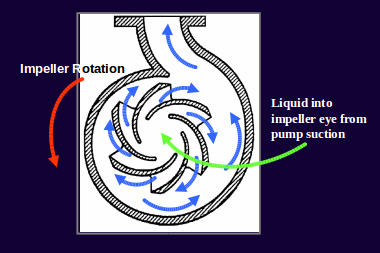
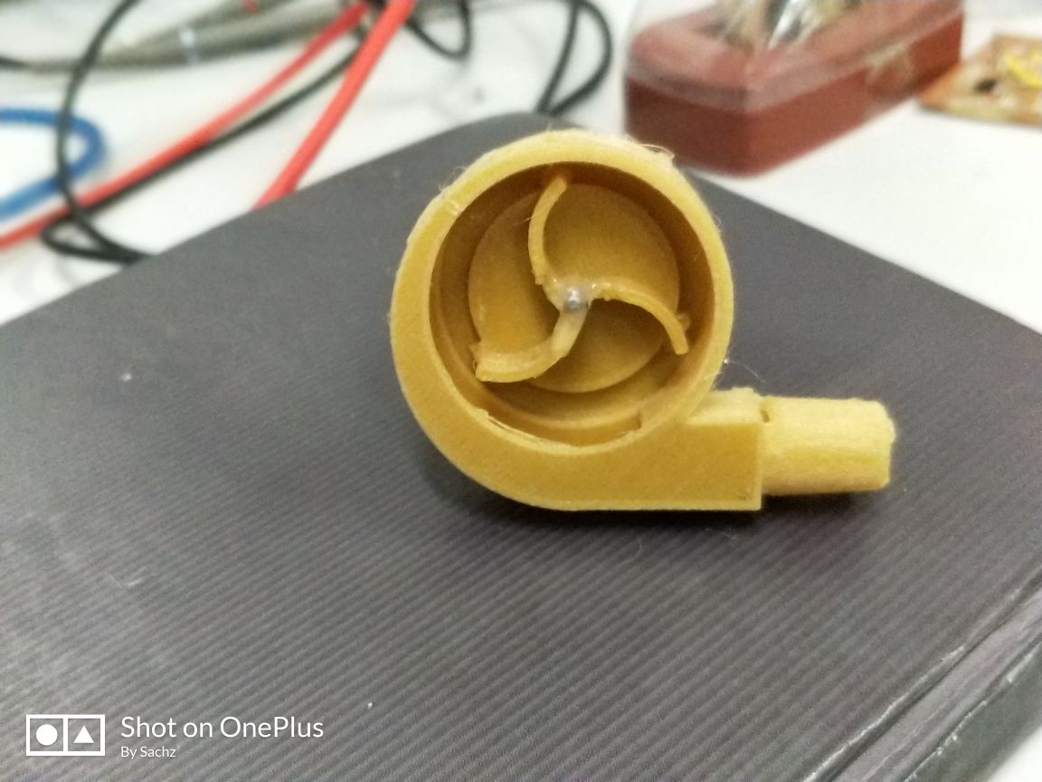
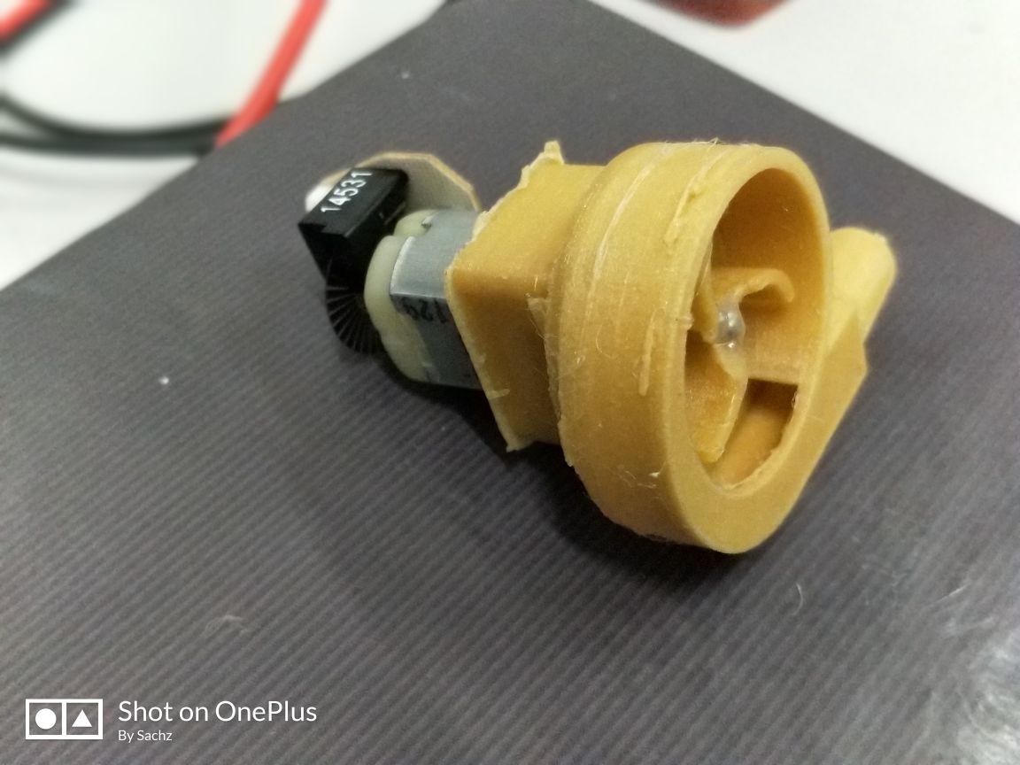
Centrifugal Pump
In centrifugl pump, as liquid enters the pump impeller eye, the blades accelerate the liquid along the convex surfaces of the impeller blades, or vanes. The liquid is thrown from the impeller blade tips into the casing.
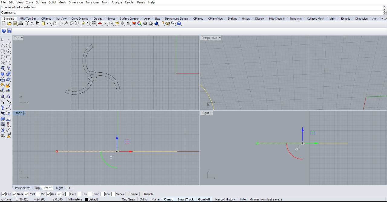
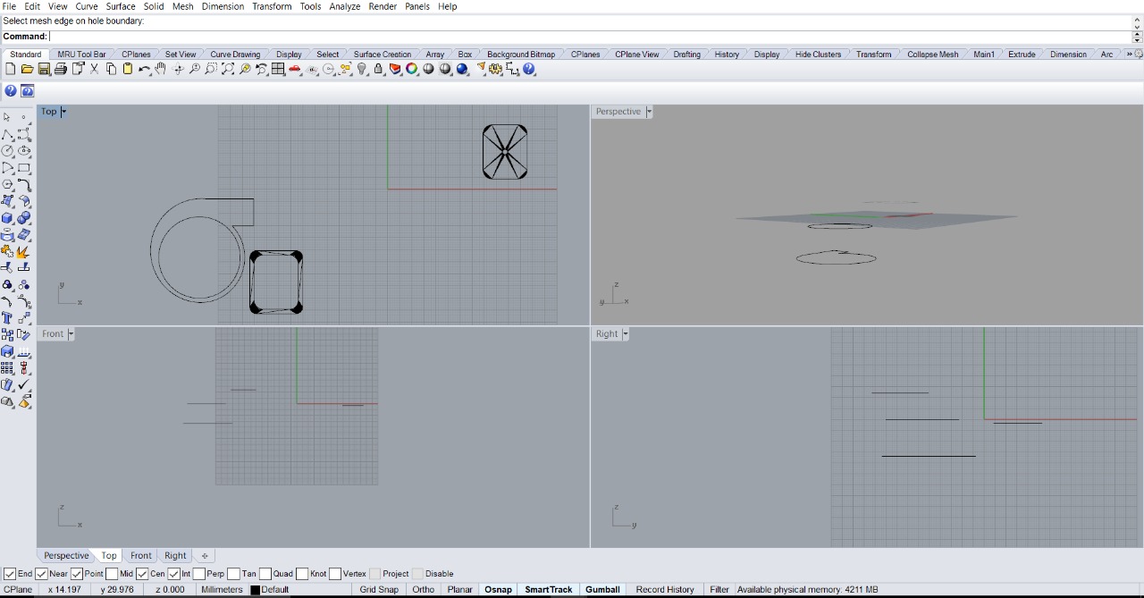
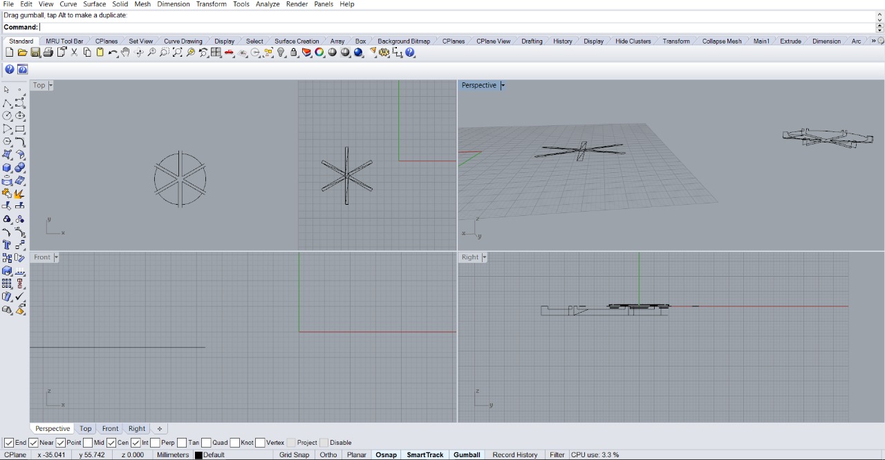
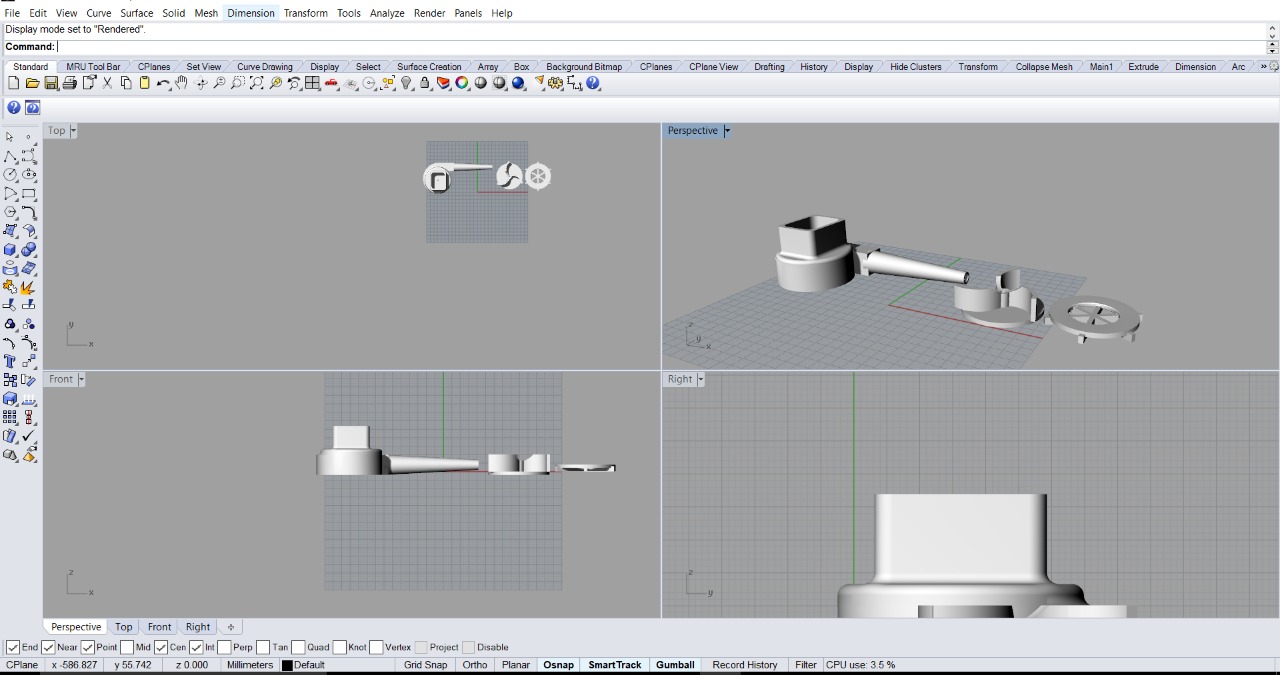
So here I first designed impeller
Then its casing
Finally the base cover
Then import it into Cura and printed my pump.
Then I connected motor to it.
Now my two pumps are ok. Diaphragm pump to pump water from main reservoir to the pipes and the second, centrifugal pump to pump nutrients from the nutrient tank to the reservoir.
Then next is about the electronics section
In Week 10 Assignment, that is Output device I've done the board and programme for running the motor.
In Week 13 Assignment, in Input Devices week I made the Satsha kit and it made bluetooth connectivity possible to ontrol the motor in final project.
In Week 15 Assignment, in I2C week I made Atmega as master to drive two boards which is connected to SDA and SCL pins of the Atmega and made motors and hence the pump to rotate.
In Week 16 Assignment, in Interface and application week I developed an app to control the pumps.
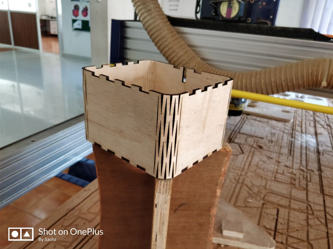
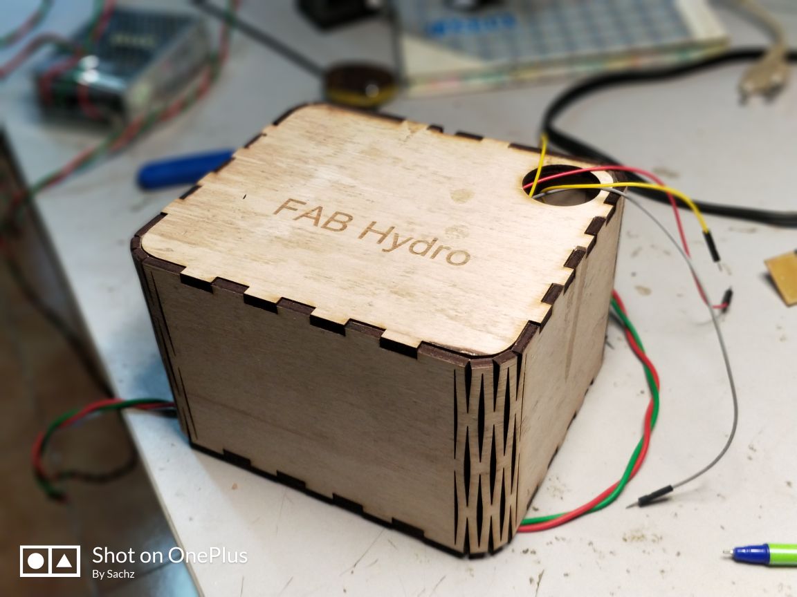
Next is to provide housing for the electronic components. Here I decided to make a lasercut wooden box.
Here I planned to make a box based on flecture design and made provisions on it for the connecting to the pumps.
Box body. First its hard to bend. But I made it possible by an old methide. Usually its possible to an extend to bend wood by vapourisation, Here what I did is that, poured some water and applied heat by using hot gun and it made the wood bend.
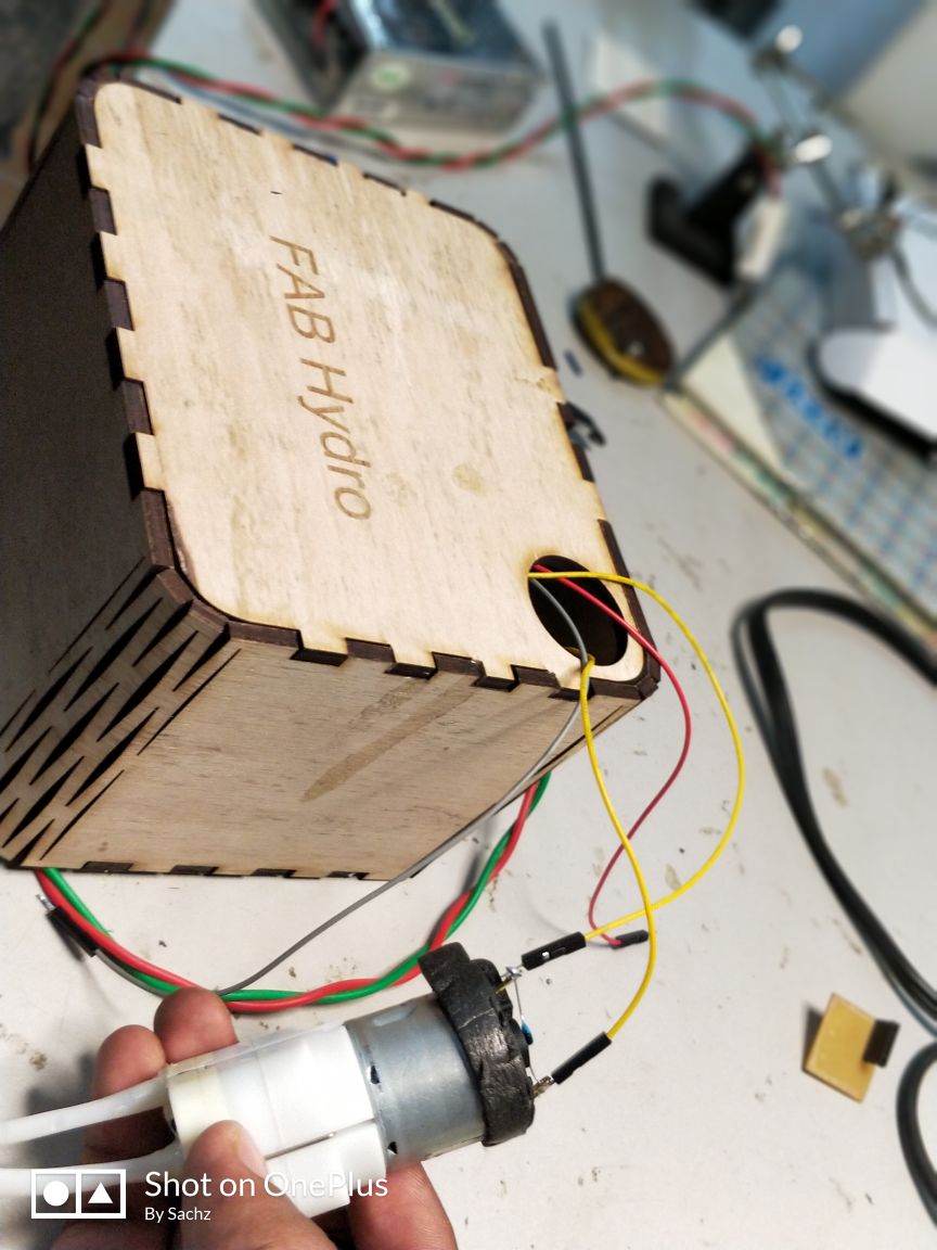
Heres the lid. In it I gave provision for taking the input for the motors
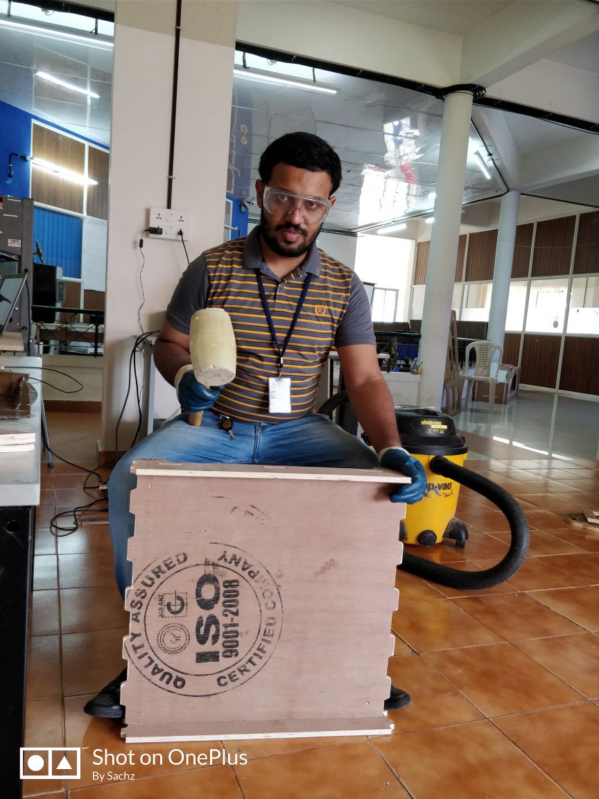
So here is how my box looks in a whole.
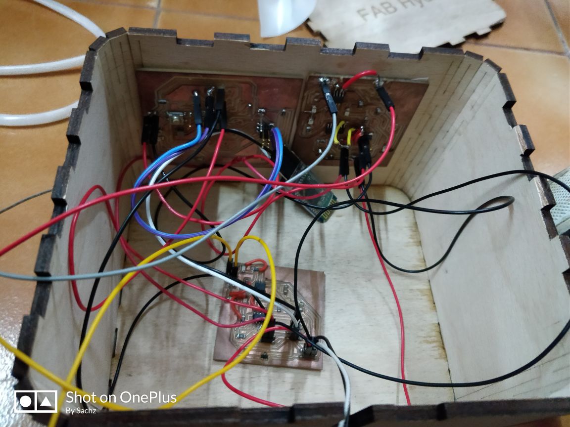
I made the two boards to stick on the box walls and the bluetooth module and driver board to place on the base itself.
Heres how the box and connection looks like. Motor is also connected.
Next is with the working of the whole system.
Here for planting, I'm planning to use coir rice. Inorder to prevent the residuals to enter the tube, I covered with cotton in the tube inlet.
Now connected the main pumps to the reservoirs and the other to the nutrient tank. Then I operated the pump using the app developed.
The water cycled properly and I could pump the nutrient to the main reservoir.