Home
Week Nine : Embedded Programming
Assignment
This week assignment is to learn about ATTINY44 microcontroller and read its datasheet
And also to program the board that was designed in week 6 with couple of programming languages
I prefer to use C and Arduino IDE to program my board
By looking into the datasheet, I had to google some words which I didnt follow. But our instructor Vinod have briefed the datasheet.Some important points to remember while using ATMEL microcontroller are as follows
Microcontroller has inbuilt system, including CPU, RAM, ROM, Timer ...
ATtiny44a - Microcontroller is what we use here
ATtiny44a is a Low power AVR 8-bit microcontroller
ATtiny44a has high performance
Its Self-programmable flashing memory is 2k / 4k / 8k bytes
Programmable EEPROM is 128 / 256 / 512 bytes
It has 10-bit ADC(Analog to digital conversion)
ATtiny44a works between operating voltage of 1.8V - 5V
ATtiny44a is an SOIC(Small Outline Integrated Circuit) with input / output package of 14 pins
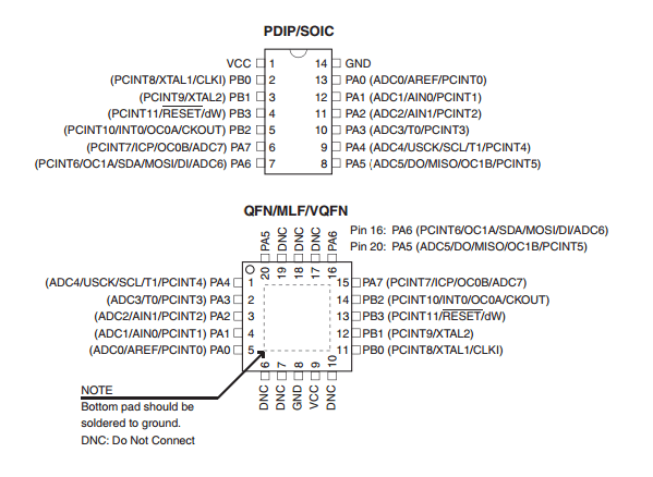
1. VCC - Supply voltage
2. GND - Ground
3. PortB(PB0,PB1,PB2,PB3) - 4-bit, biDirectional input / output port with internal pull-up resistors
>>RESET - Acive low reset, Instead of reset pin, use program "RSTDISBL" fuse
>>Resonator is added to increase the clock frequency.Internal clock frequency is 1MHz.Resonator is added to get 20MHz
4. PortA(PA0 - PA7) - 8-bit, biDirectional input / output port with internal pull-up resistors
>> MOSI(Master Out Slave In) - Data output from master
>> MISO(Master In Slave Out) - Data output from slave
BLOCK DIAGRAM

ATtiny24A/44A/84A are low-power CMOS 8-bit microcontrollers. By executing powerful instructions in a single clock cycle, the ATtiny24A/44A/84A achieves throughputs approaching 1 MIPS per MHz allowing the system designer to optimize power consumption versus processing speed
ARCHITECTURAL OVERVIEW

Programming
Developed a program in Arduino
Combile using "Verify"
Programmed the board using "Upload"


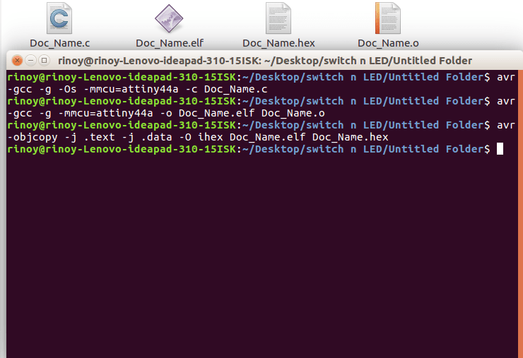
After programming, Follow these steps to compile in AVR GCC
Make a document and save as (.c) file
Open the terminal
avr-gcc -g -Os -mmcu=attiny44a -c Doc_Name.c
"Doc_Name.o" file is created
avr-gcc -g -mmcu=attiny44a -o Doc_Name.elf Doc_Name.o
"Doc_Name.elf" file is created
avr-objcopy -j .text -j .data -O ihex Doc_Name.elf Doc_Name.hex
"Doc_Name.hex" file is created
Copy ".make" file and rename it to Makefile
Edit the Project = "Doc_Name" and save
make
make program-usbtiny-fuses
make program-usbtiny
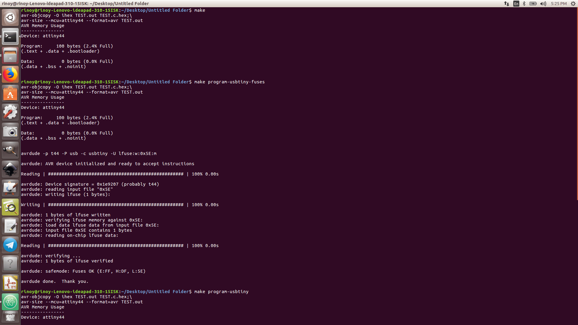
The program is successful and video is shown below
Group Assignment
Comparing the development and performance workflows for other architectures
Microcontrollers are often described as single-chip computers. They contain a microprocessor core, some memory and various devices such as parallel i/o ports, serial i/o ports, timers, analogue to digital converters (ADC's) etc.
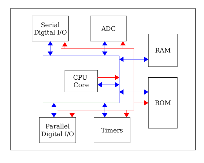
Red lines represent the address bus, blue lines represent the data bus
Central Processor Unit
Central Processor Unit is responsible for executing stored program (in ROM) and managing the peripherals. It fetches numeric instructions from memory (opcodes) one by one, interprets them and carries out some operation as a result. CPU mainly consist of some components like Registers, ALU and Instruction Decoder
Registers are a little like internal memory storage areas. These are useful for interim calculation results.The arithmetic logic unit is responsible for carrying out calculations.In some CPU's this can be quite simple; perhaps only supporting add, subtract and basic logical operations.instruction decoder's job is to translate numeric opcodes into sequences of actions
Data bus is a collection of wires that are used to transport numbers into and out of the CPU. A logic '1' on each line of the bus is represented by a particular voltage commonly 5V or 3.3V. Logic '0' is commonly represented by a 0V signal
Address bus is another collection of wires used to select which of the memory locations is allowed to use the data bus
Random Access Memory & Read Only Memory
RAM - Random Access Memory is used for storing values that are liable to change during the course of the execution of a program.RAM contents are usually lost each time systems are turned off/on
ROM - Read Only Memory does not lose its contents when power is removed. Thus it is generally used for storing programs
Serial Input / Output
Serial communications requires the sender to send data 1 bit at a time a rate agreed with the intended receiver. Each bit is given a time slot, the sets the transmit wire to the correct logic level for each bit's time slot. The receiver measures the voltage arriving from the sender at the middle of each bit's time slot. It can thus decide whether a '1' or '0' has been sent for a particular bit
Parallel Digital Input / Output
Microcontrollers send and receive information to the outside world using ports. There are many different types of port however the simplest is the parallel I/O port. These ports can be thought of as memory cells or registers that are connected to the CPU core using the data bus and also tothe outside world via pins on the side of the microcontroller
Timers
Timers are typically constructed using a clock source and a counter.Counters count clock periods that are input to them
ADC's and DAC's
Frequently microprocessors are required to process non-digital .analogue (or continuous) signals. In order for them to do this, a special device called an Analogue to Digital Converter is required.This device accepts an analogue input and translates this to a digital number
Interrupts
Very simple microprocessor systems are often built which execute only one task
PIC Microcontroller
PIC is a family of microcontrollers made by Microchip Technology.PIC micro chips are designed with a Harvard architecture, and are offered in various device families. The baseline and mid-range families use 8-bit wide data memory, and the high-end families use 16-bit data memory. The latest series, PIC32MZ is a 32-bit MIPS-based microcontroller. The PIC architecture was among the first scalar CPU designs and is still among the simplest and cheapest
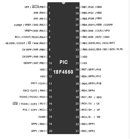
PIC18F4550 device in PIC18 family. PIC18F4550 is an 8-bit RISC architecture microcontroller. Its specifications are
Timer: One 8-bit and three 16-bit Timers i.e. Timer0-Timer3
USART: 1 In-built Enhanced USART
ADC: 10-bit 13 channel ADC
Capture, Compare and PWM module (CCP) and Enhanced CCP module
USB: USB V2.0 support transfer speed 1.5Mb/s to 12Mb/s
Master Synchronous Serial Port (MSSP) having I2C and SPI protocol
256 Bytes of EEPROM, 32Kbytes of Flash memory and 2KB internal SRAM
PORTS: A, B, C, D and E
Streaming Parallel Port for USB streaming transfers
Three External Interrupt
Oscillator
8051 Microcontroller
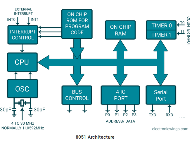
The 8051 is the first microcontroller of the MCS-51 family developed by Intel Corporation in 1980. It was developed using N-type Metal-Oxide-Semiconductor (NMOS) technology, and later it came to be identified by a letter C in their names, e.g. 80C51 which was developed with Complementary Metal-Oxide-Semiconductor (CMOS) technology which consumes less power than NMOS and made it better compatible for battery-powered applications
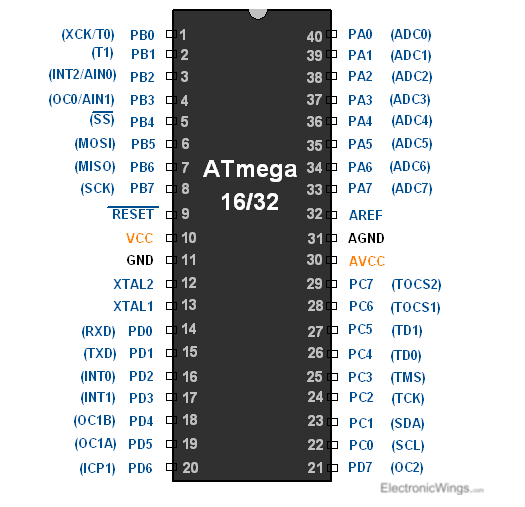
AVR Atmega 16
ATmega16 is an 8-bit high performance microcontroller from the Atmel’s Mega AVR family. Atmega16 is a 40 pin microcontroller based on enhanced RISC (Reduced Instruction Set Computing) architecture with 131 powerful instructions. It has a 16 KB programmable flash memory, static RAM of 1 KB and EEPROM of 512 Bytes. The endurance cycle of flash memory and EEPROM is 10,000 and 100,000, respectively AVR ATmega16 has 32 pins constituting four ports.PORT A, PORT B,PORT C,PORT D.Each port has 8 pins.these pins of these four ports can be used as general purpose inputs/outputs
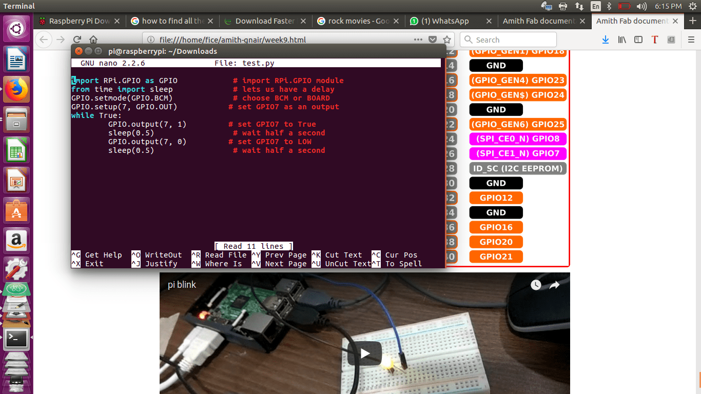
We Used RaspberryPi
RaspberryPi is a credit card sized computer used used widely for education purposes.This deviceis used to improve the progrramming skills and hardware understanding at pre-university level.
RaspberryPi OS - Raspbian
RaspberryPi Programming language - Python
RaspberryPi Processor - Broadcom
RaspberryPi Hardware - Ethernet, USB and Input / Output ports
RaspberryPi Other Features - WiFi and Bluetooth support
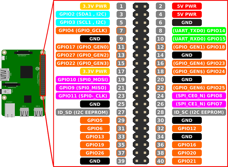
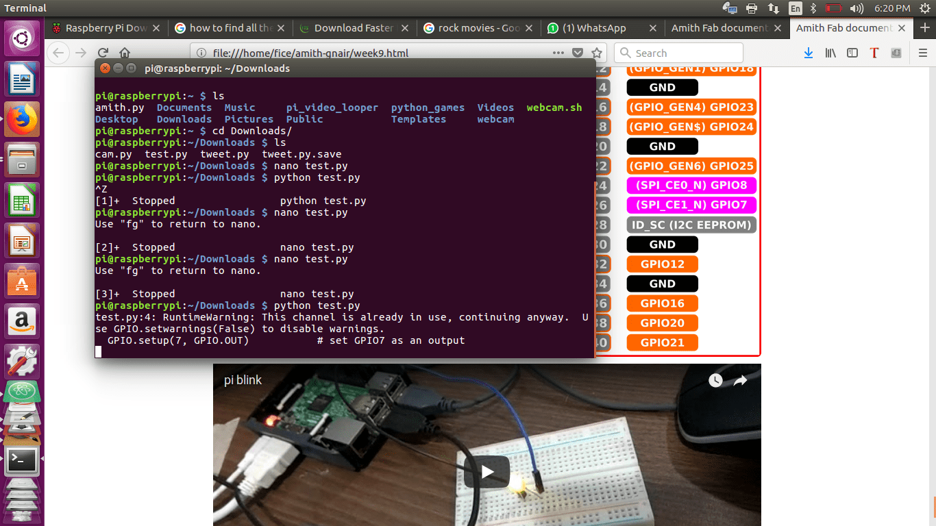
Wrote the program using python and saved as "test.py" file
