Home
Week Eight : Computer-Controlled Machining
Assignment
This week assignment is to Design something big using CNC (Computer Numeric Control) machine.
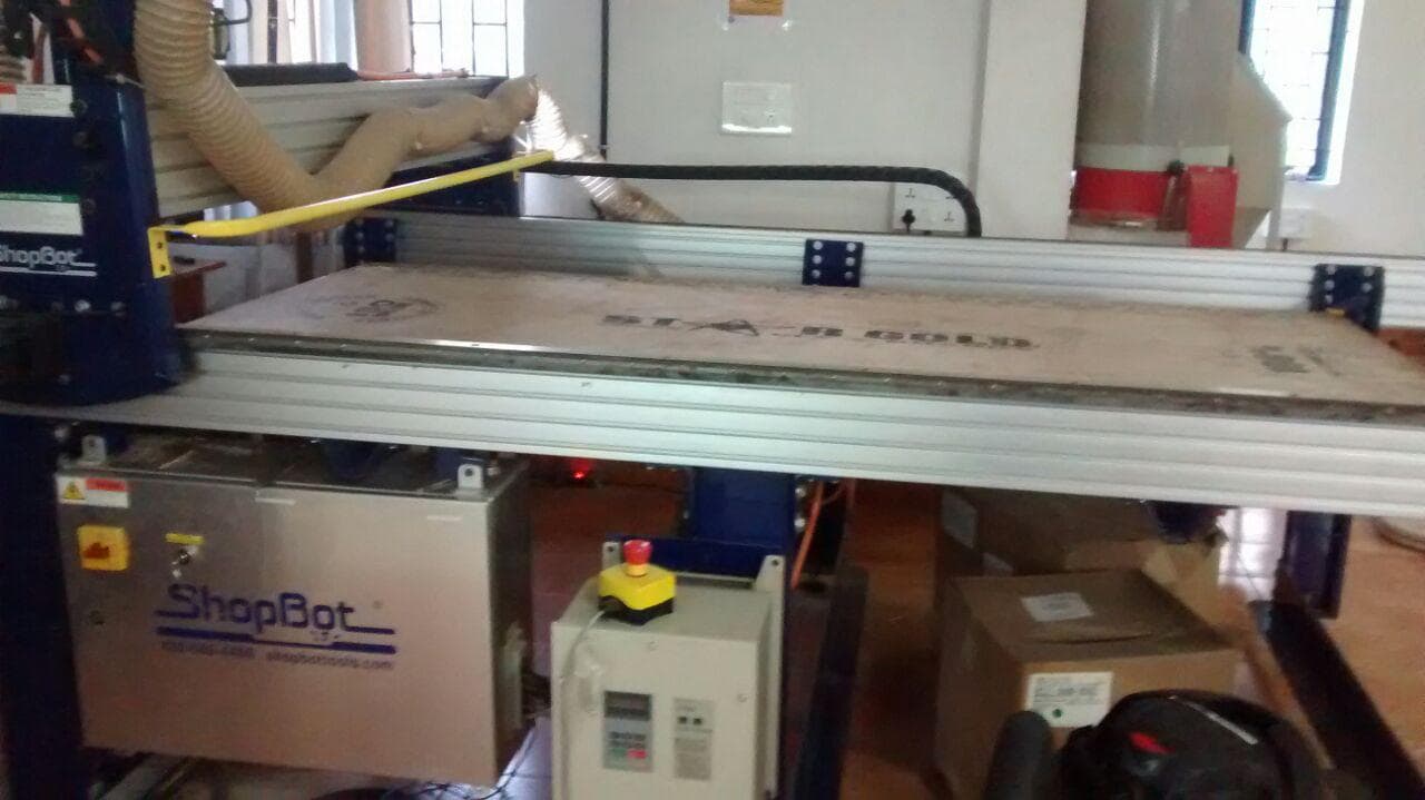
CNC machine is the automation of machine tools by means of computer executed pre-programmed sequence of machine controlled commands.
Shopbot has 3 axis movement(x,y,z)
Shopbot is used to cut and carve materials like : Wood, Plastic, Styrofoam and many other.
Shopbot has position accuracy to (+/-)0.2
File Format : DXF / STL
Software used : VCarve
Material size given : 2440*1220*120 (mm)
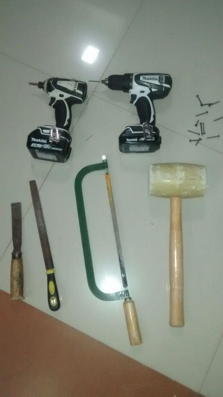
Tools Used
Cordless Power Drills
Hammer
Chisels
Hand File
Hacksaw
Screws
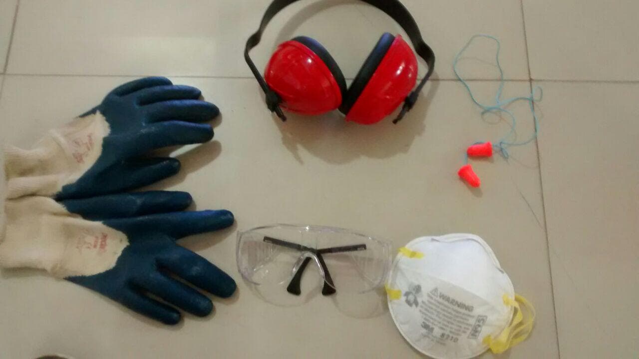
Safety
Safety is the main feature for this week.
Our Professor Neil Gershenfeld warned us about the safety measures in weekly review
Goggles
Ear Plug
Gloves
Boots
Avoid loose dress and untied hair
Always be near to Remote STOP switch or SPACEBAR in computer to stop / pause the work
Group Assignment
Group assignment is to make a test Runout, Alignment, Speeds, Feeds and Toolpath of SHOPBOT
We have gave tolerance upto 0.2
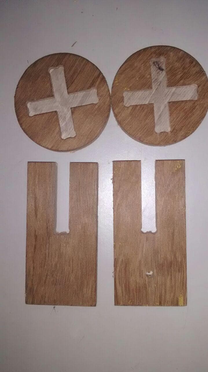
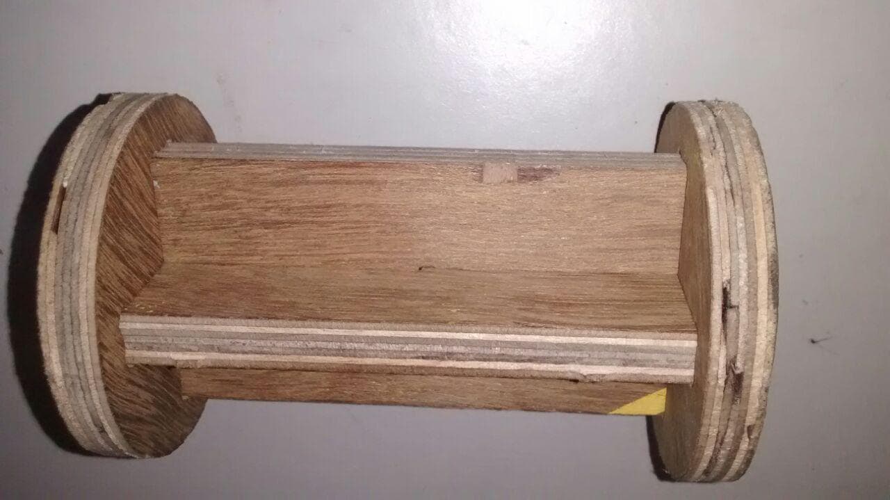
Made pockets and cross fits
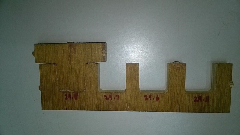
Testing Runout, Alignment, Speeds, Feeds and Toolpath of SHOPBOT
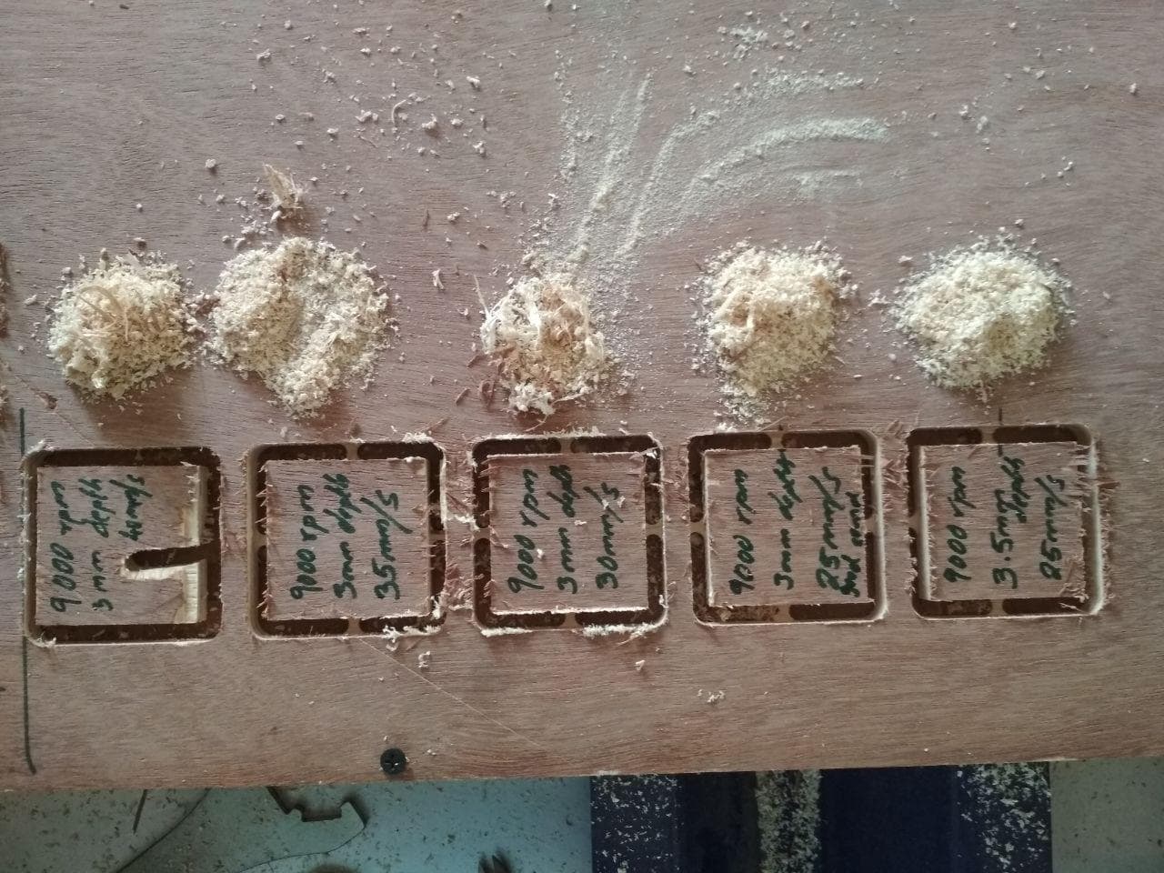
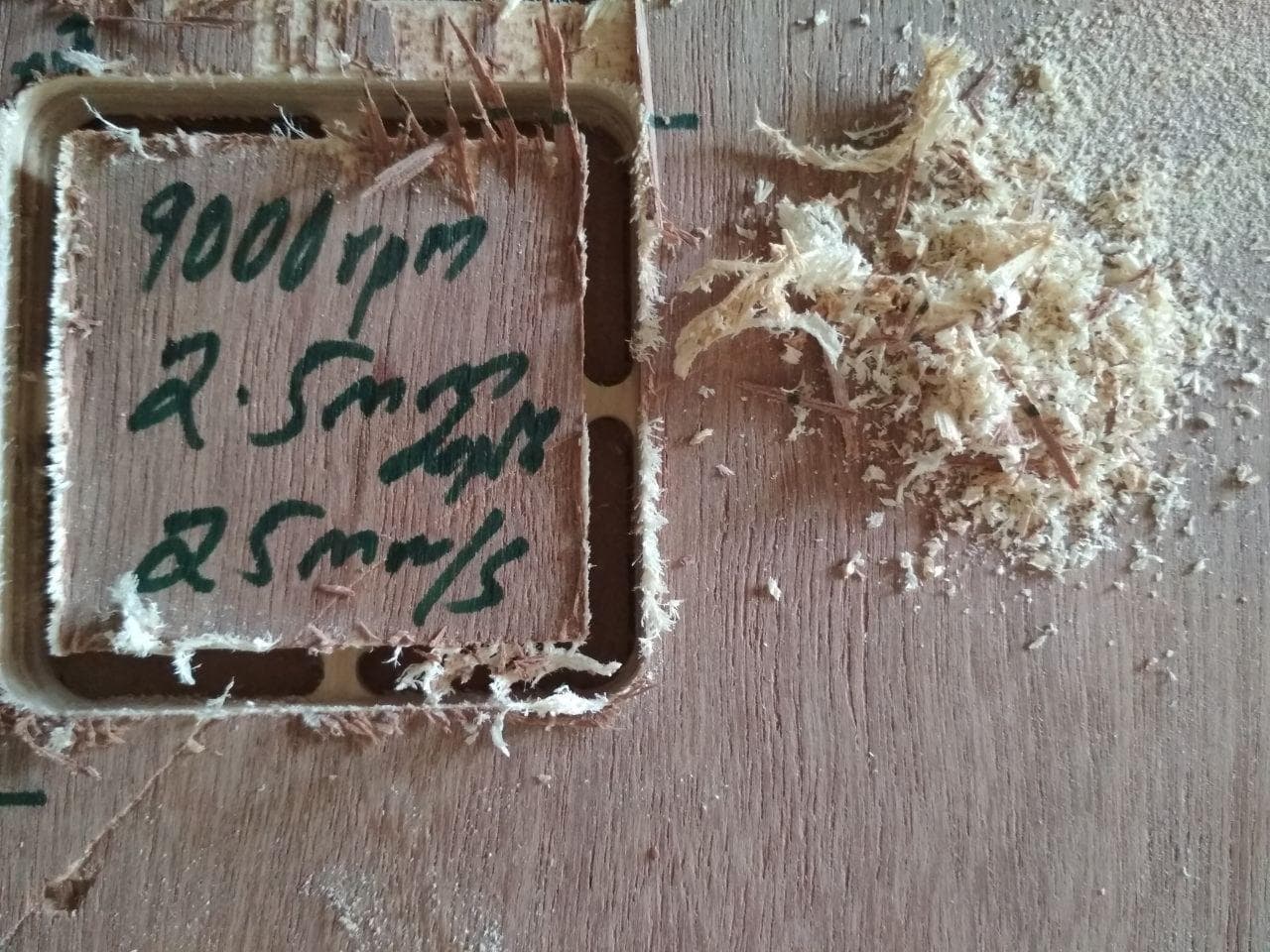
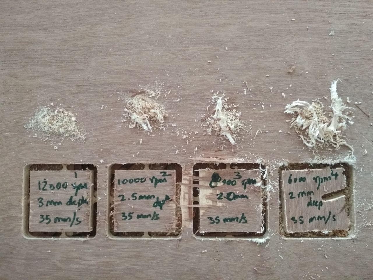
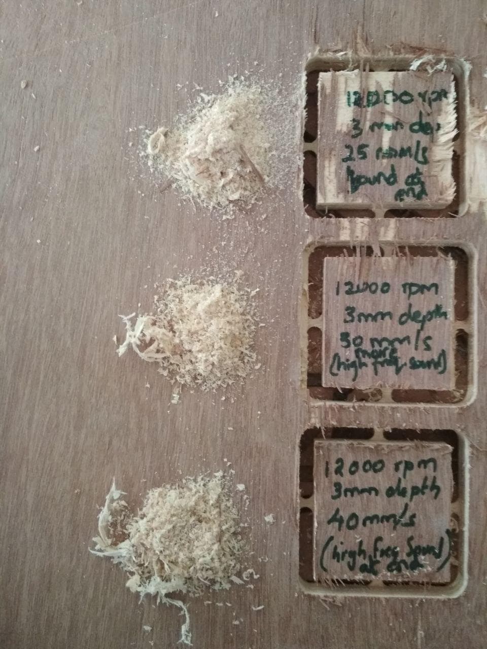
We have tried keeping Speed constant and varying feed rate and depth
And we have collected the chip formed during the machining process to observe the fine cutting rate
As instructed by our instructors, we tested many and We were able to find out that with 9000rpm, 3mm depth and feedrate of 25mm/s gives the best finish
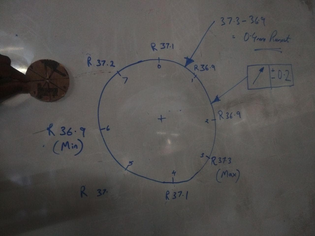
Testing Runout >> +/-2 mm
Run-out or runout is an inaccuracy of rotating mechanical systems, specifically that the tool or shaft does not rotate exactly in line with the main axis
Run-out is dynamic and cannot be compensated. If a rotating component, such as a drill chuck, does not hold the drill centrally, then as it rotates the rotating drill will turn about a secondary axis
Run-out has two main forms:
Radial run-out is caused by the tool or component being rotated off centre, i.e. the tool or component axis does not correspond with the main axis. Radial run-out will measure the same all along the main axis
Axial run-out is caused by the tool or component being at an angle to the axis. Axial run-out causes the tip of the tool (or shaft) to rotate off centre relative to the base. Axial run-out will vary according to how far from the base it is measured
Absolute alignment is impossible; a degree of error will always be present
My Assignment
I had gone through previous students websites and I thought about making something useful for our FabLab.
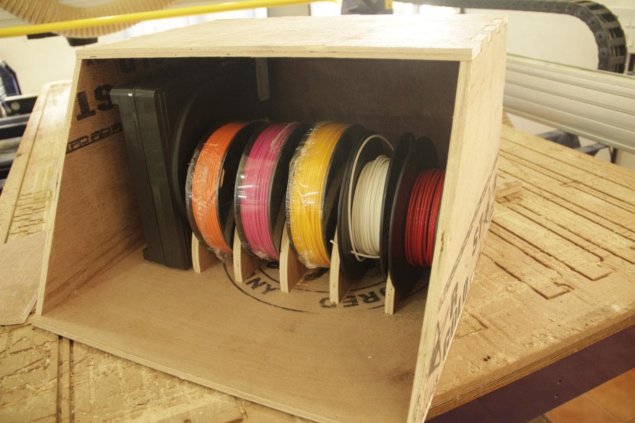
From Previous weeks, I was told about 3D printer material(PLA) should be kept under low humidity, and here it is kept in open. So I cameup with an idea for making a Box to store PLA material inorder to keep it away from humidity.
Here in trivandrum - Kerala, we have high humidity.Our Instructor Lancy and Vinod helped me with the thought and also guided me in designing.
I named it : De-Humidifier
This is just a box which can atleast reduce the humidity.I had made this my project, so I can do inovative ideas to keep away humidity from PLA
I have used Fusion 360 on designing and used NX9 to join the 3D view, so i get a clear picture what Im into.
Used Fusion360, NX9 and Autocad
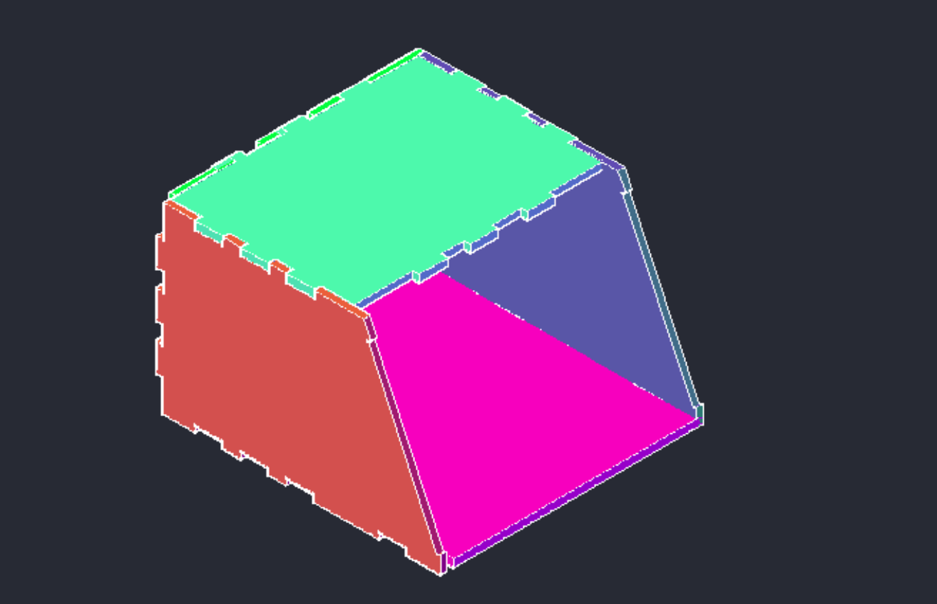
Using Fusion 360, I had designed my De-Humidifier Box
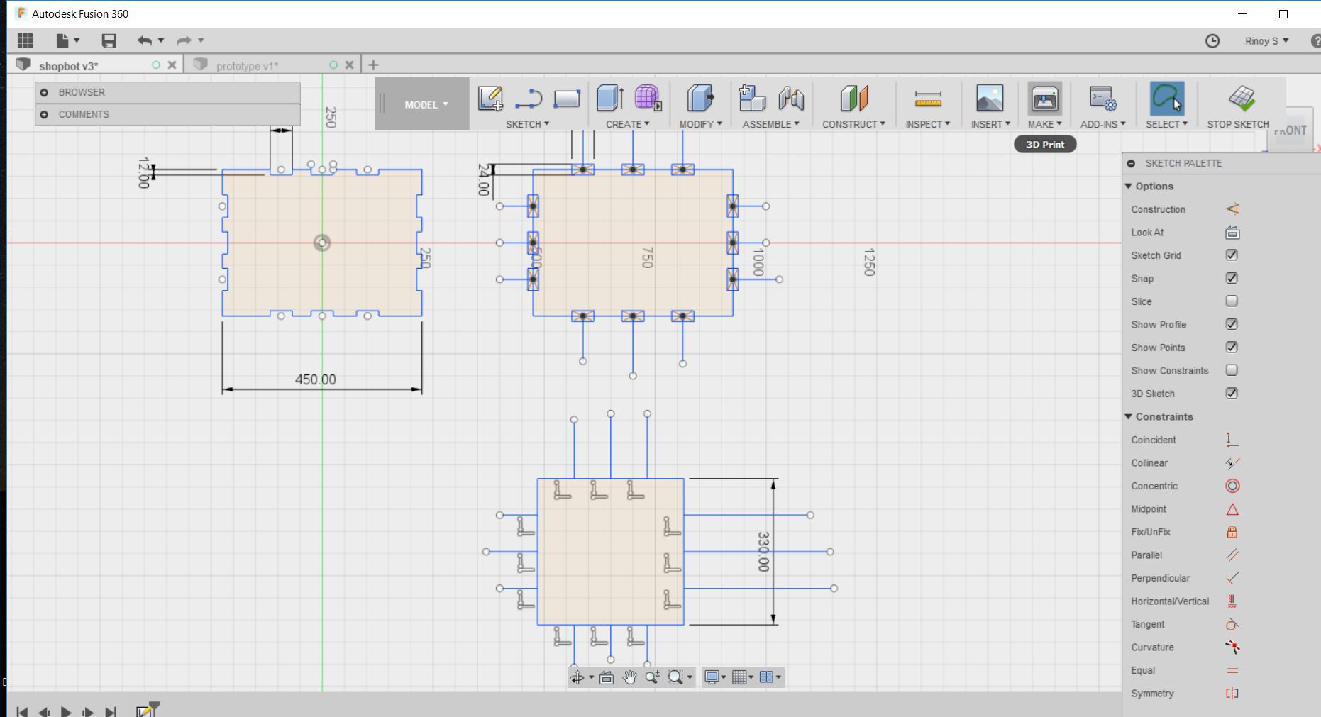
I had used NX9, to view in 3D and exported as CAD file and opened in Autocad and arranged each parts
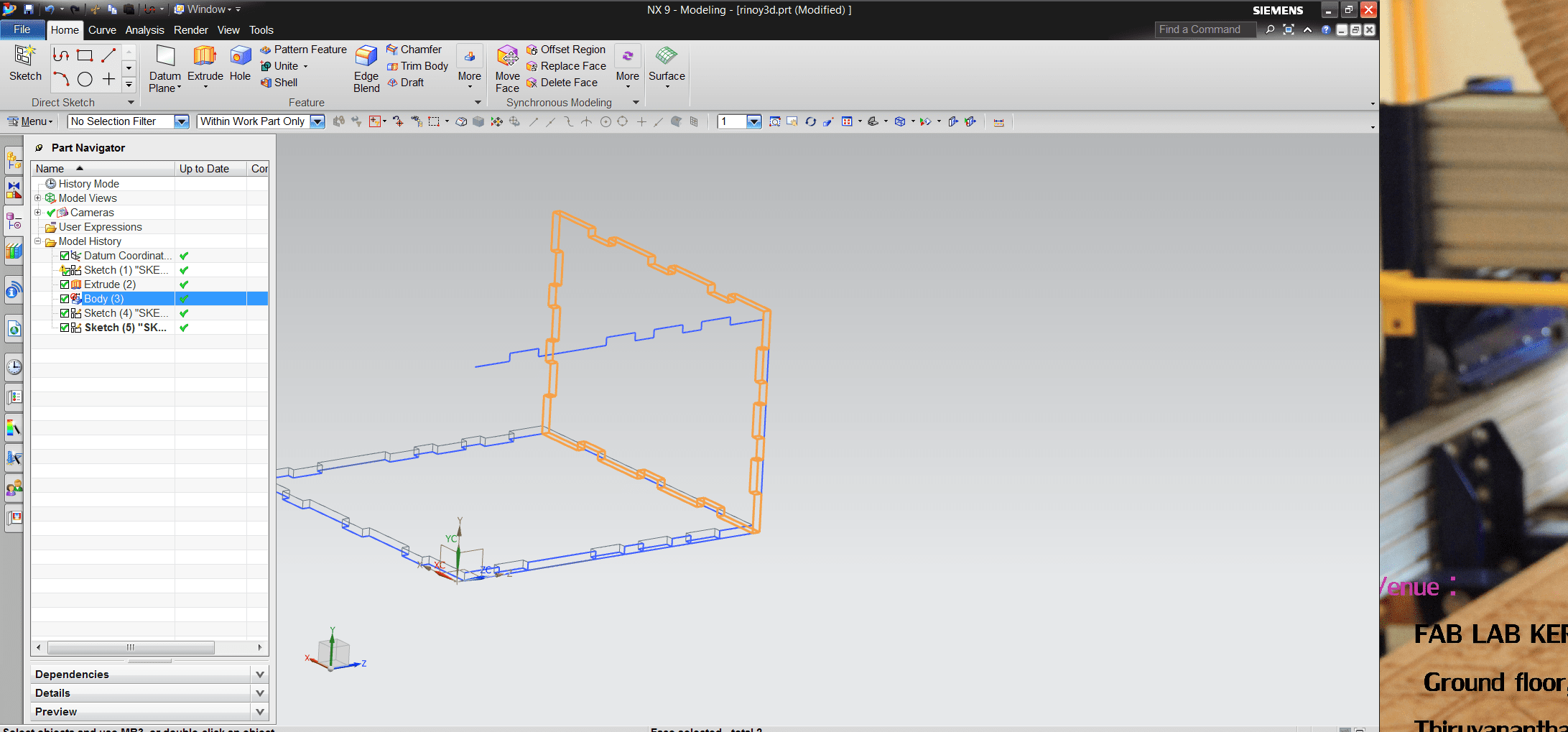
3d view using NX9
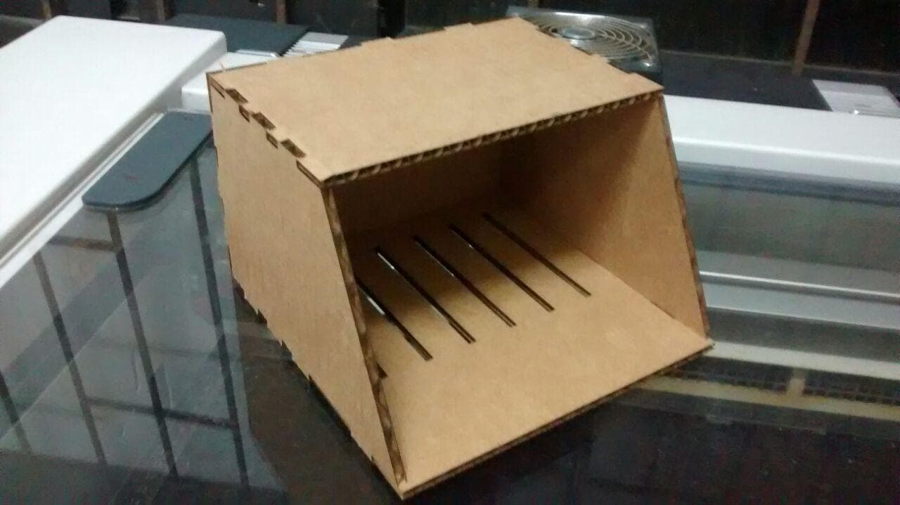
Used Laser-Cutting Machine to take a look at my Prototype
Tool Cut Type
End Mills
Shaft Diameter: The shaft diameter describes the width of the cut made by the end mill
Flute: The flute is the sharp edge of the end mill. An end mill commonly has one, two, or four flutes. Flutes can be straight, meaning they're parallel to the length of the end mill shaft, or they can have a spiral profile along the length of the shaft
Profile: The profile of the end mill is the shape of the profile of the bit looking at it from the side. There are many different kinds of profiles, but the most common are ball-nose and flat
Cut Direction: There are upcut, downcut, and compression cut end mills
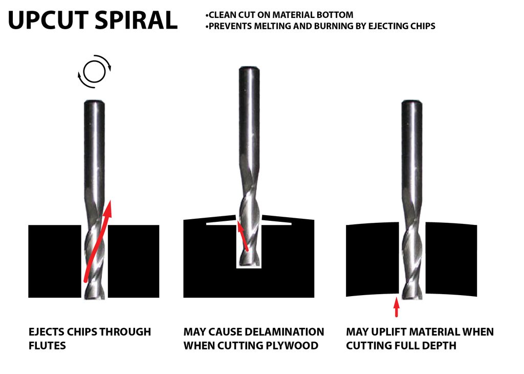
In an Upcut type end mill the teeth on the flute will point upwards. This means that the end mill is cutting and drawing out the wood through the flute. This is good for cutting deep into the stock. But this leaves a bad surface finish on the top of the surface
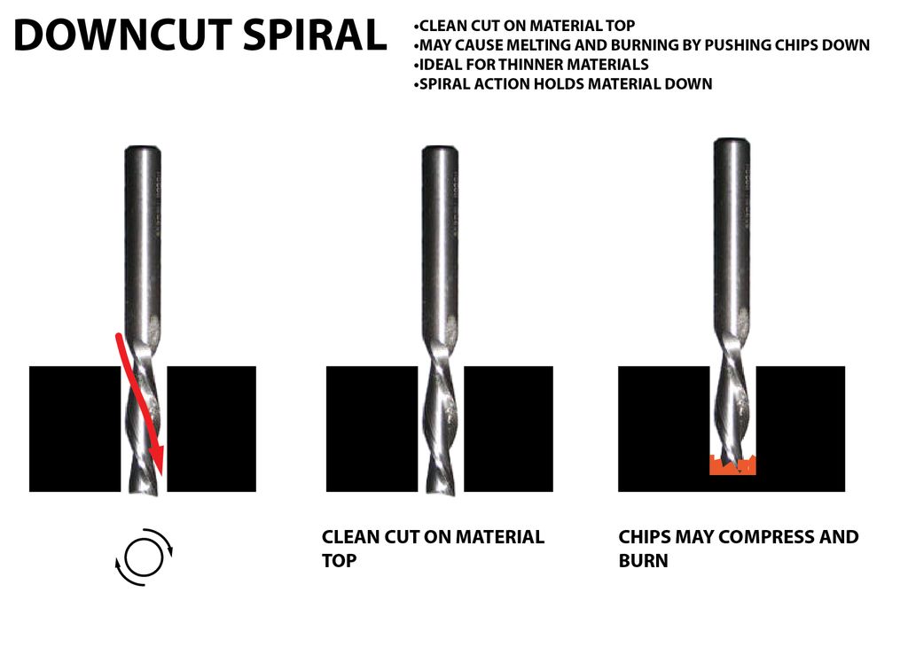
A downcut type end mill has teeths that point downward on the flute. This means that the end mill will cut and try to push the material into the stock. This will give good surface finish on the top, but it is not very efficient at removing material
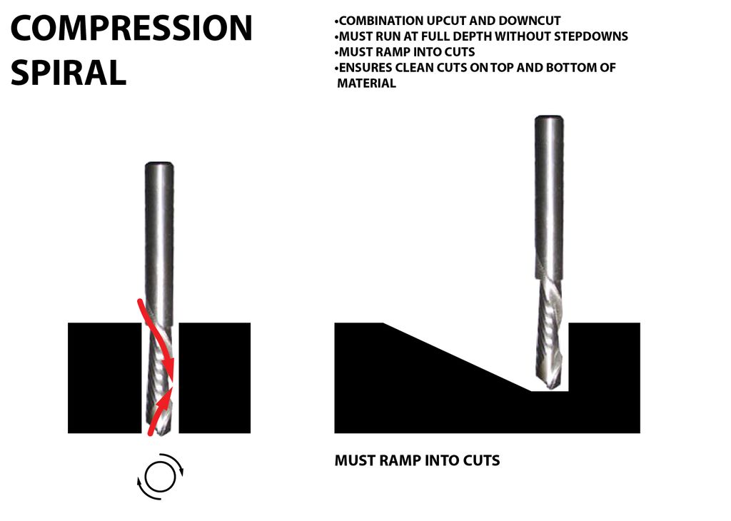
Compression spiral bits are a combination of upcut and downcut bits. The lower third of the bit has an upcut orientation, and the upper two thirds have a downcut orientation. This end mill results in clean cuts on the top and bottom of the material while avoiding the burning and lifting issues of downcut and upcut bits
Chip load : This is the amount of material that is removed in each chip. The value is approximately = feed rate (inches per minute) / (RPM x number of flutes)
Cut depth : This is the measure of how deep the end mill should go in each step while milling. Ideally cut depths should be less than 1/3rd of the length of the tool. They are mentioned in the product manual of the tool bits
How to Cut with Shopbot
hopbot runs on a series of commands called G-Code.These commands tell tool head where to move, how fast to move and what to cut
This is usually the first step we have to design what we are going to cut. For cutting, we need a 2D vector path of the part. Design the cutting part and export it as the .DXF file which can be used by Vcarve
For controlling shopbot, we need to generate a G-code file from the CAD, to do that we need a CAM software. We use Vcarve for generating the shopbot file from the CAD design
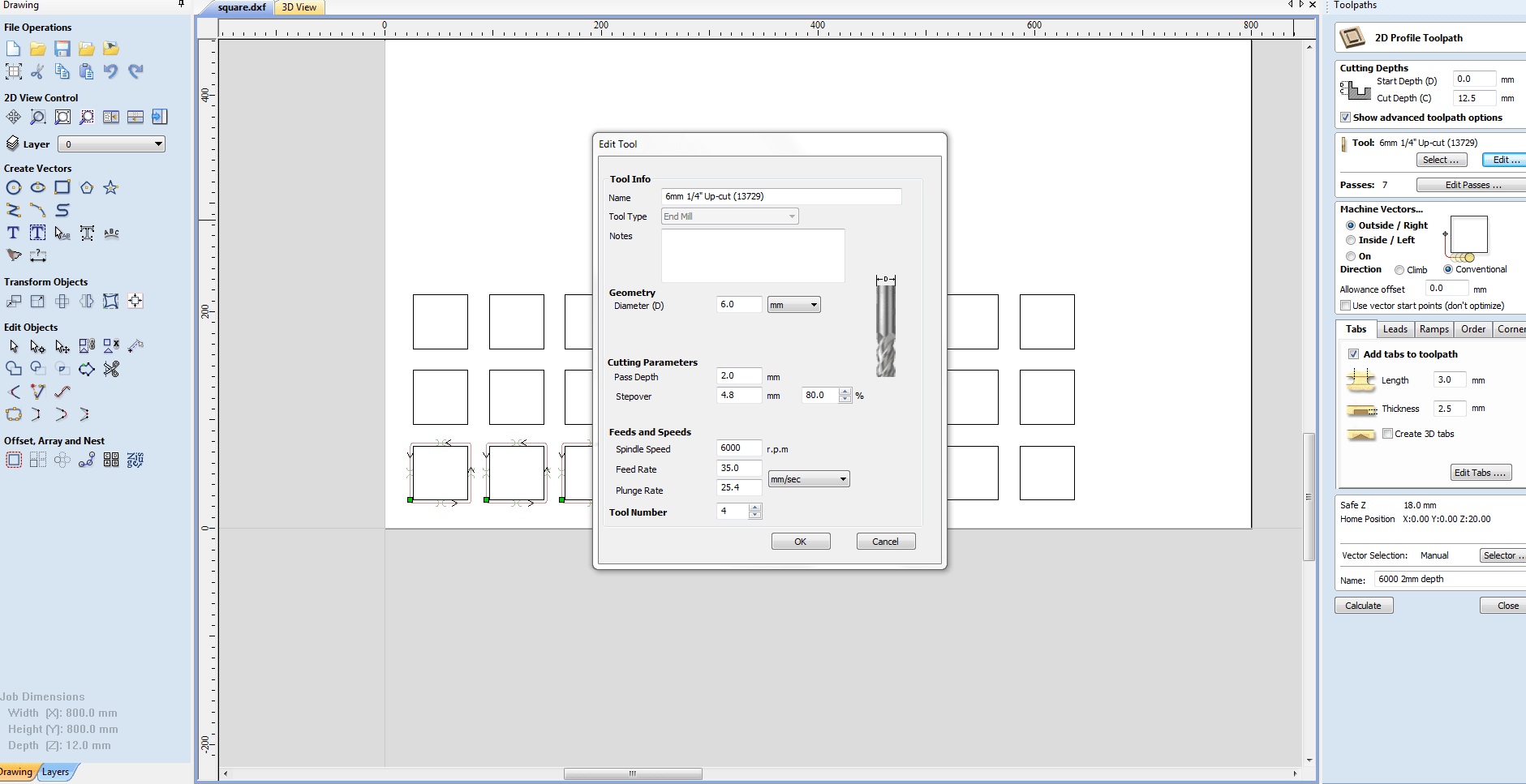
Settings on ShopBot and VCarve
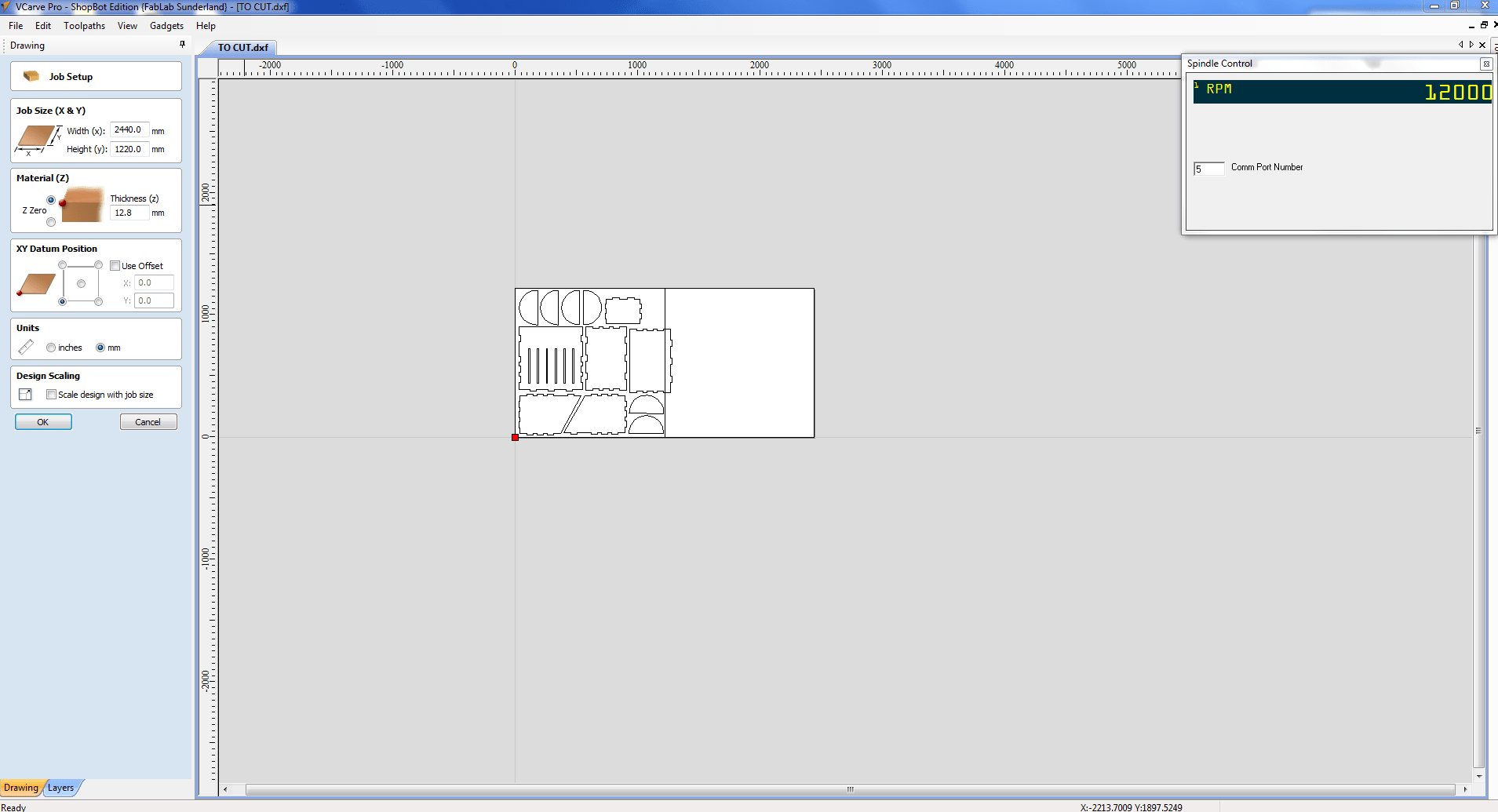
Step 1 : Open the design in VCarve - Shopbot Edition
Step 2 : Check the settings
Job Size (X&Y) >> Width(x) : 2440mm
Job Size (X&Y) >> Width(y) : 1220mm
Material (Z) >> Thickness(z) : 12.8mm
Step 3 : Join Open Vector
Tolerance : 1mm and JOIN
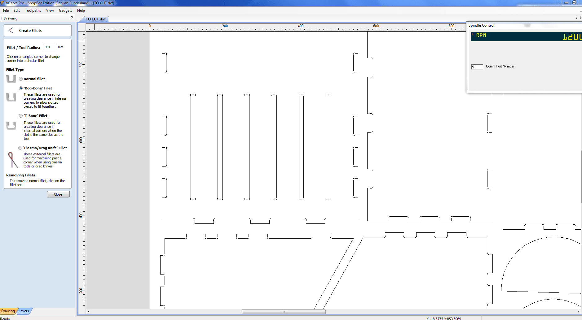
Step 4 : Dog Bone Joint
Create fillet >> Tool Radius : 3mm
Create fillet in each and every corner of our design individually
Step 5 : Material Setup
Clearance : 6mm
Plunge : 6mm
Home / Start Position
Step 6 : To Hold the material to Bed - Putting Screw hole setting
Create vectors >> Draw Circles of dia 6mm >> Apply
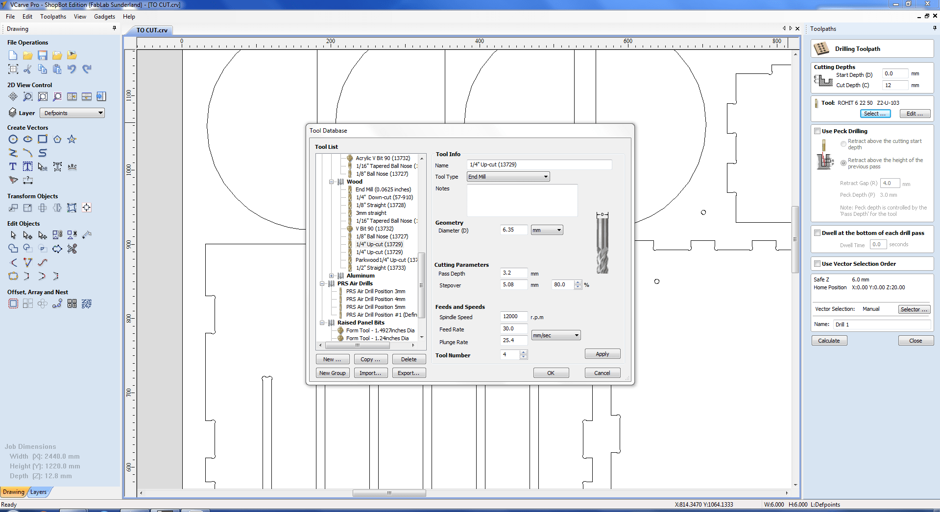
Select Tool
Draw circles in material where we want support.Circle of 6mm is the tool path,so we can know that tool wont pass over the screw
Change settings for Drilling Toolpath from TOOLPATH OPERATION
Cut Depth : 12mm
Select Circles
Calculate
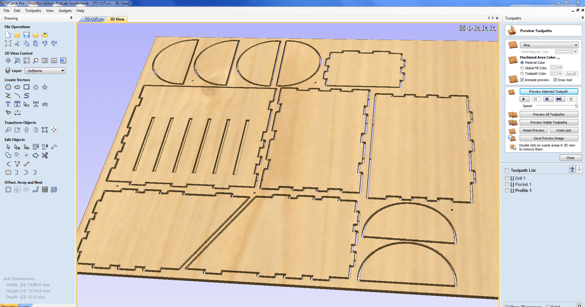
Preview selected toolpath
Here we can clearly see, where the holes are going to be drilled in our work material
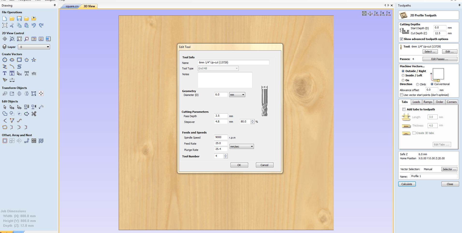
Step 7 : Adding Pockets to design
Change settings for Pocket Toolpath from TOOLPATH OPERATION
Select Tool
Cut Depth : 8mm
Select all pockets which is to be drilled
Calculate
Preview selected toolpath
Here also we can clearly see, where the pockets are going to be drilled in our work material
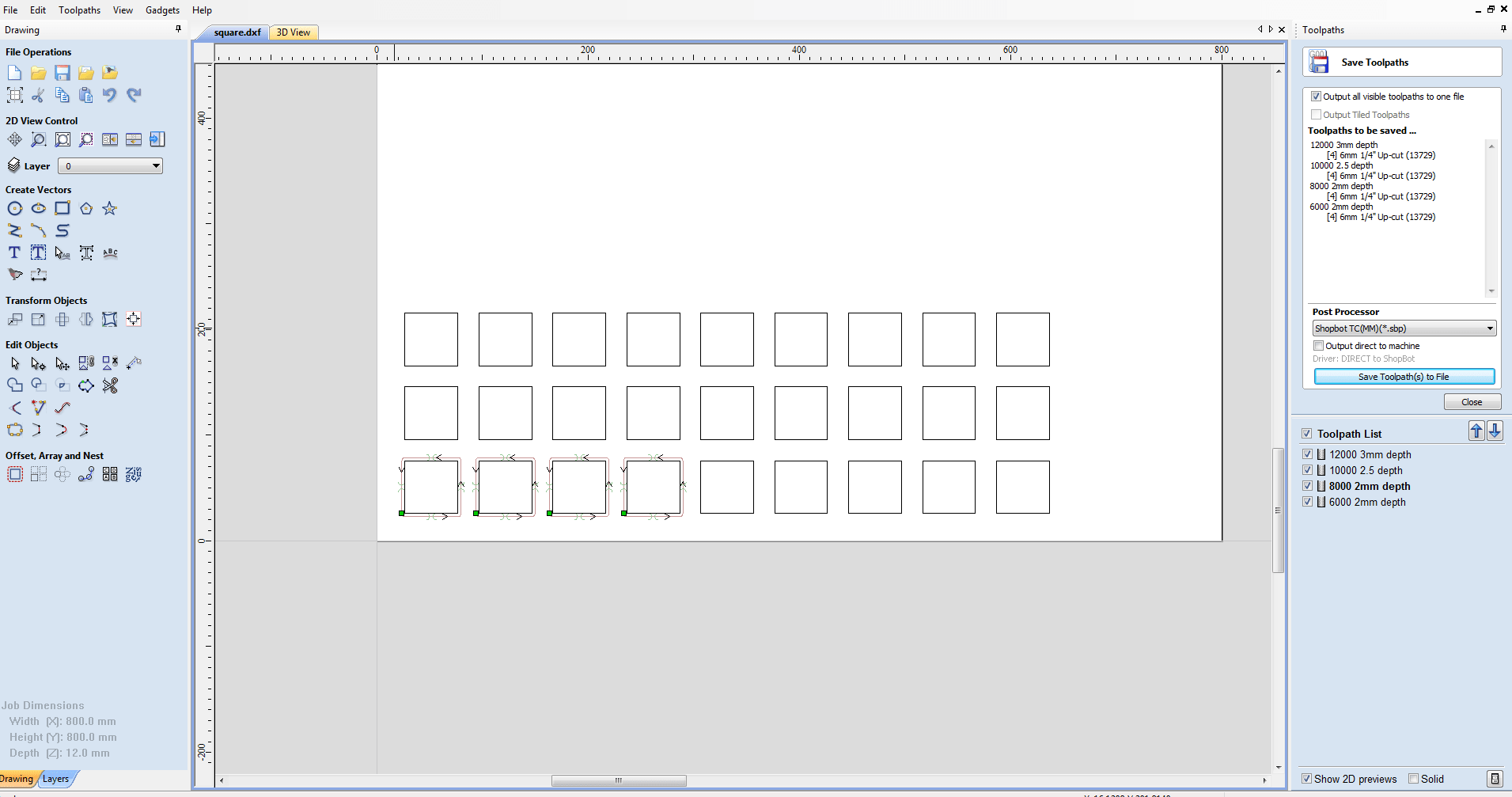
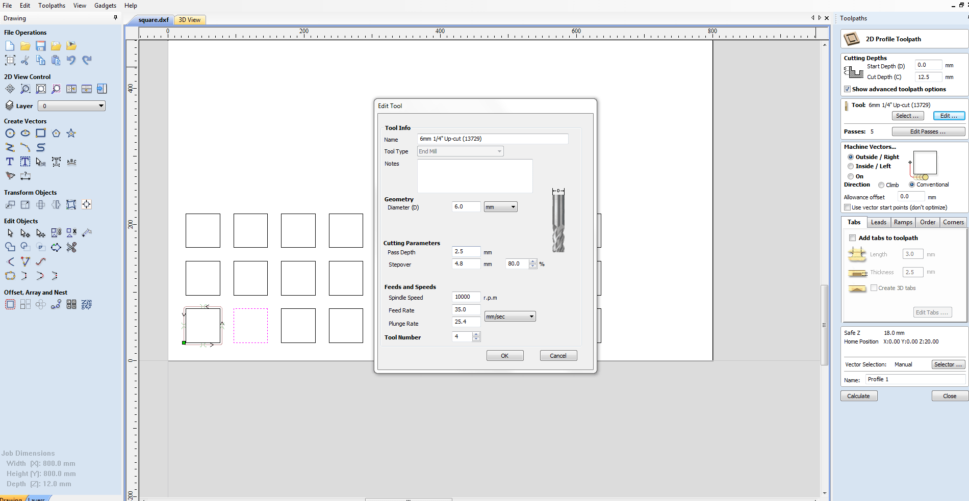
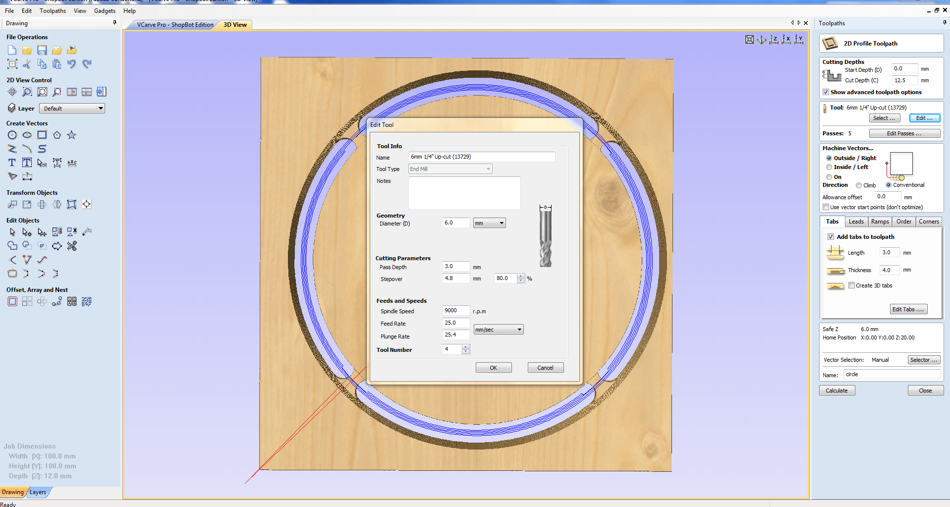
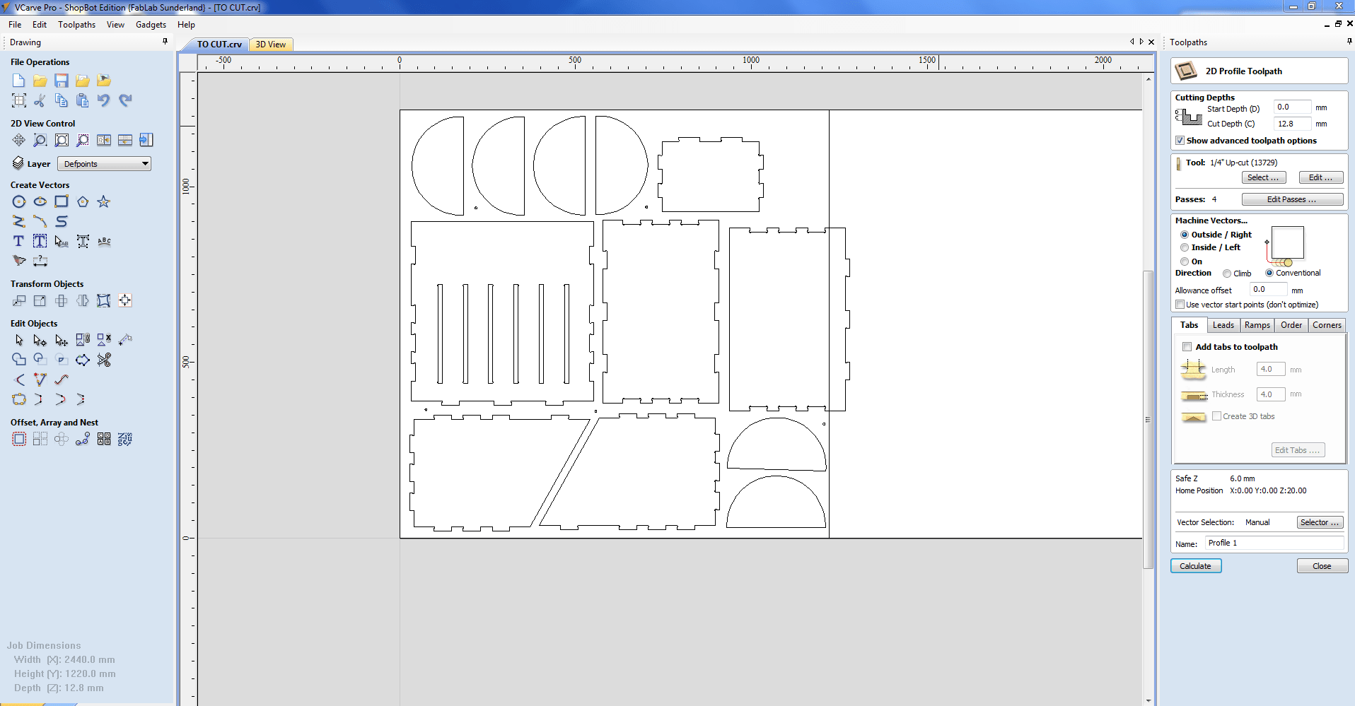
Step 8 : Final - CUT
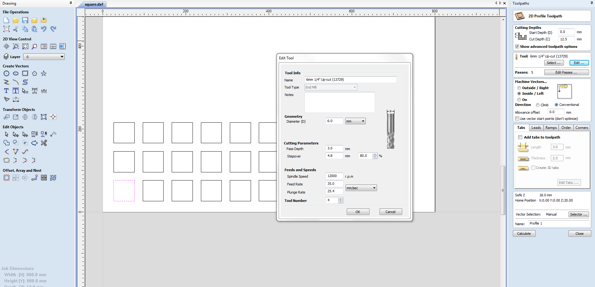
Change settings for Profile Toolpath from TOOLPATH OPERATION
Select Tool
Cut Depth : 12.8mm
Select the design to cut,machine cuts according to the selection
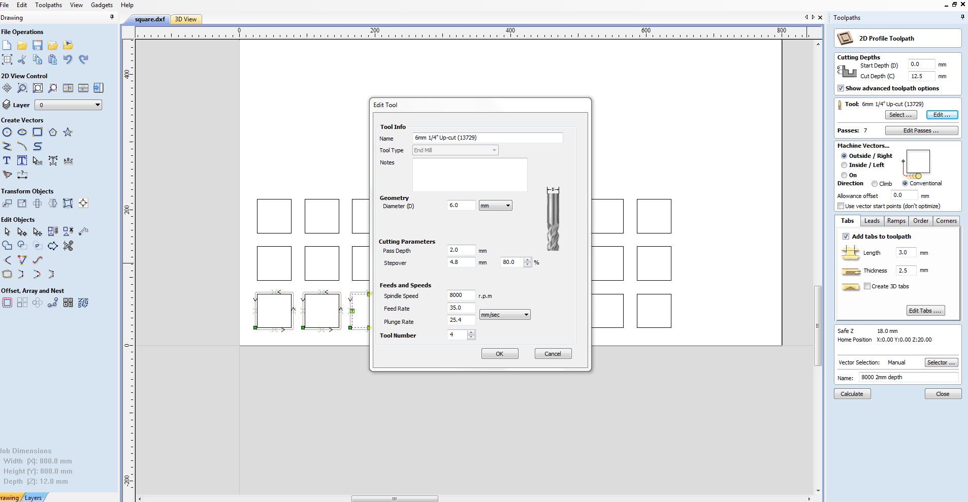
Step 9 : Add TABS to hold the cut pieces to the material
Edit Tab >> Add Tab
Preview
Select Cut type
Inner Cut / Outer Cut / On Cut
Step 10 : Save the files with these settings
Save as ".sbp" file
This is the G-code for Shopbot
Step 11 : Bed Setting - Shopbot
Open SHOPBOT 3
Set X,Y,Z axis to Zero using the keypad
Z can also be set using Zero_setting plate
Step 12 : Drill - Shopbot
Click CUTPART and select the saved "sbp" file
START BUTTON
Check whether the Tool is in spindle
Check whether Z axis is Zero
Check whether Spindle Key in ON
OK
Screw using Cordless power drill
Step 13 : Pocket And Cut - Shopbot
Click CUTPART and select the saved "sbp" file
START BUTTON
Check whether the Tool is in spindle
Check whether Z axis is Zero
Check whether Spindle Key in ON
OK

My Work