Home
Week Five : Electronics Production
Already I have explained my Engineering background was Mechanical, So I dont have a good knowledge on Electrical Electronics. So I was excited this week to learn new technology.
Our instructor Vinod has given a wonderful session on the basic Electrical and Electronics.
Yadu also given a great idea on milling machine.He also gave an idea how to use tool bit without wear and tear.
Characterizing the specification of our PCB production process
while characterizing we found that our milling tool bit is only able to mark trace upto 0.20, It doesnt have the accuracy to mill the thickness of 0.001 and 0.01.
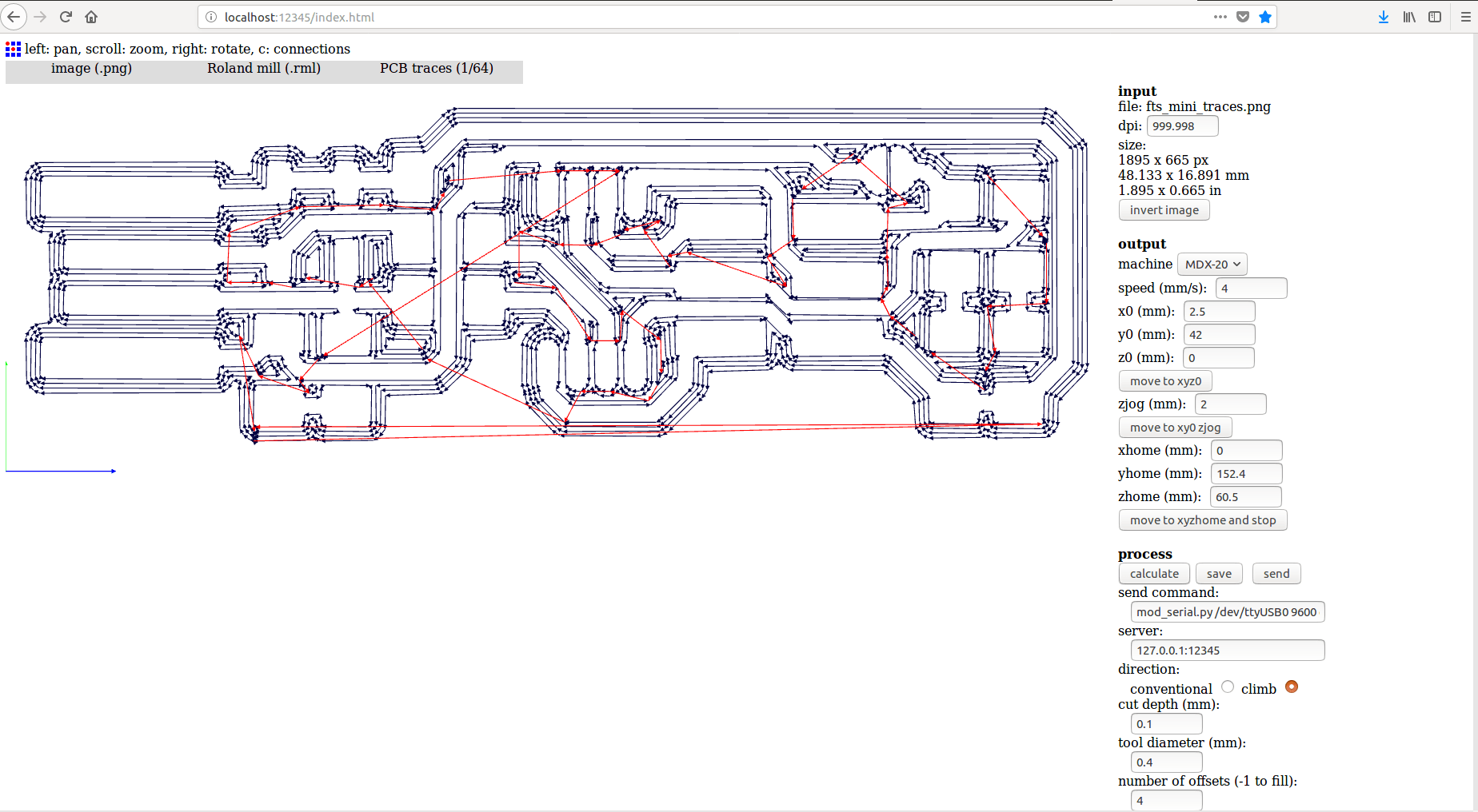
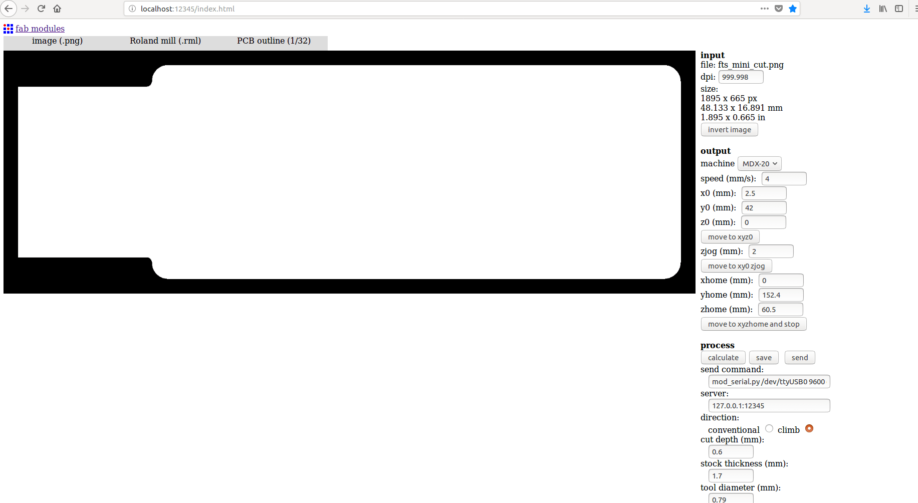
Software : Offline FabModules
Input Format : Image(.png)
Output Pocess : Roland mill(.rml)
Select Tool : PCB(1/64) - for Milling
Select Tool : PCB(1/32) - for Cutting
Set Axis : Set X, Y & Z
Select Machine : MDX-20
Calculate
Sending : Send
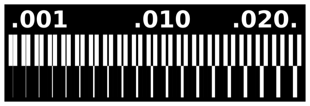

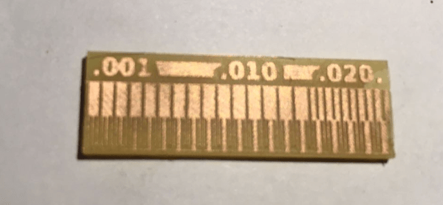
Found out that machine is not able to make trace of thickness "0.01" and "0.001" due to wear and tear of tool bit and aging of machine
Making an Circuit Programmer
I chose Brian's website for making an in circuit programmer
Design Files

Milling Machine
Milling machine is used to machine flat surface.Here we used to mill tracks and cut the PCB(Printed Circuit Board).There are single side PCB's,double sided PCB's as well as multi layered PCB's available.
In single side PCB's we have a copper layer above a substrate of non conducting layer.In double sided PCB's we have two layers of copper at top and bottom of the substrate whereas in multi layered PCB's we have alternating layers of copper between substate layers
Machine we are using is Roland Modella MDX-20
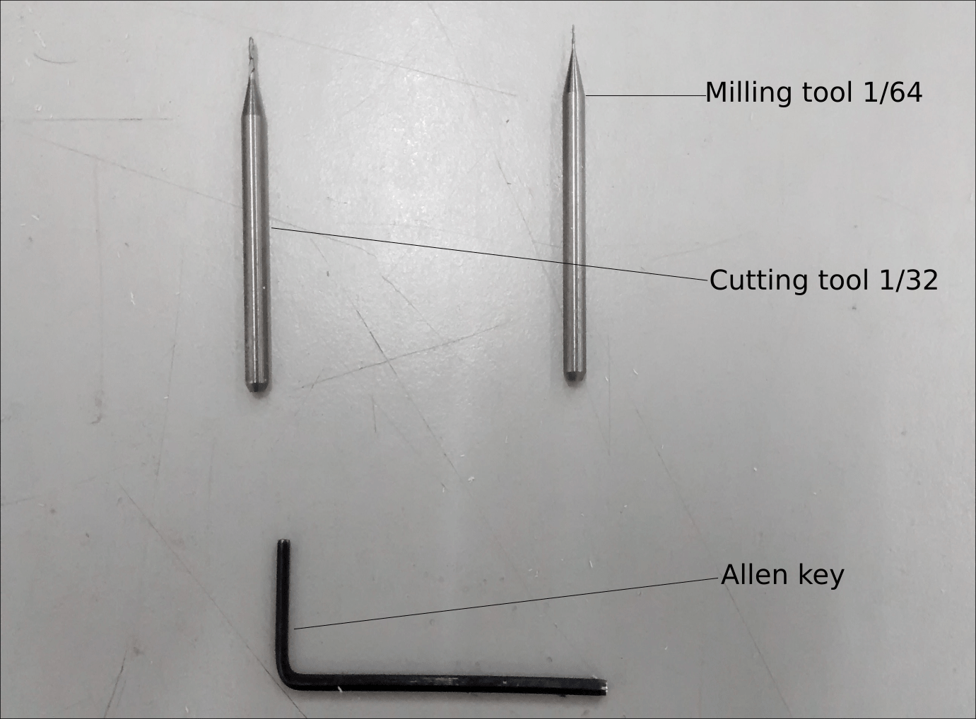
Tools used in Milling Machine
We use two types of tool in milling machine for milling tracks and cutting process.
Tools used are shown in image below.
(1/64) - for Milling
(1/32) - for Cutting
Fixing the copper board on the table
Double sided tape is applied to the copper board and set the board on the bed
Software used in Milling Machine- MDX-20
Software : Offline FabModules
Setting X,Y& Z axis in Milling Machine- MDX-20
First set the tool and give the cordinates for X,Y & Z in FABMODULES and move
Then adjust the tool so that tool touches the bed and Calculate and Send
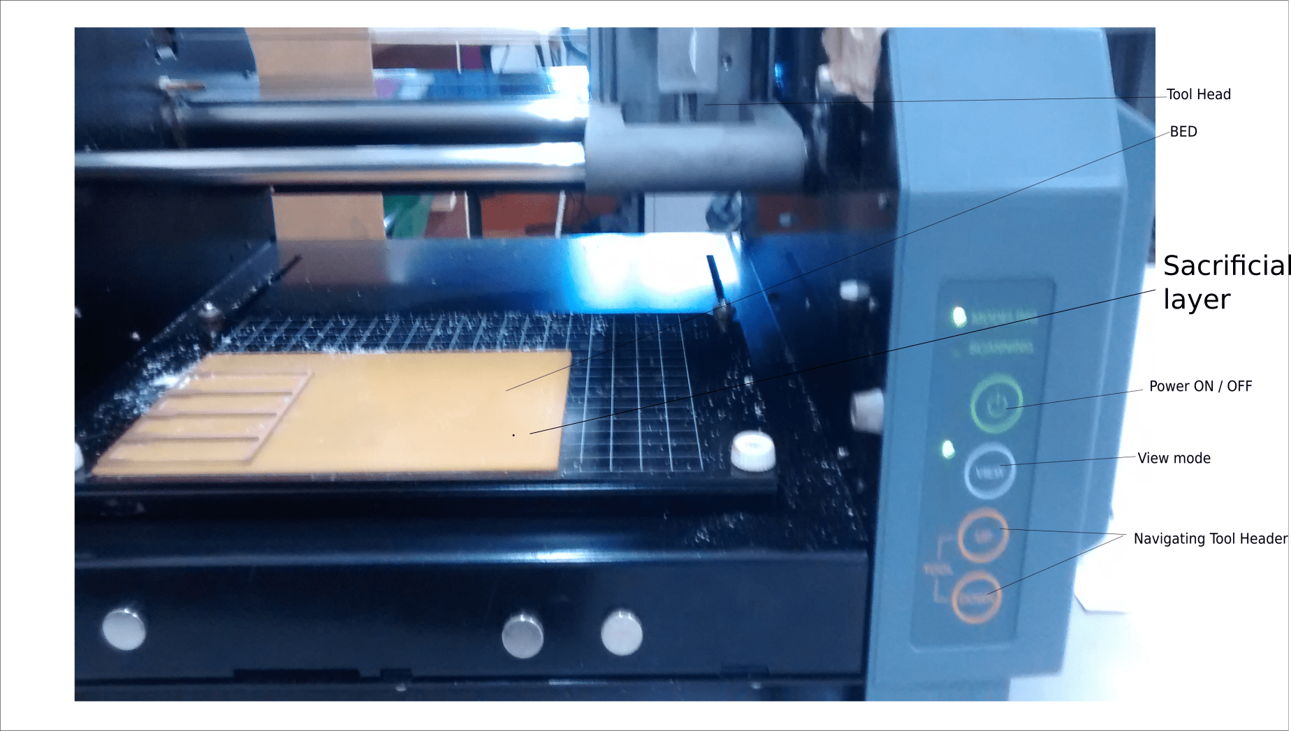
Setting Tool to Zero- MDX-20
Now going to the Rolland Modella MDX-20, there is a bed to keep the PCB for machining. Before starting it is really important to have the bed levelled, Even a 1mm level difference is a huge difference when it comes to milling the PCBs, it will result in broken endmills or uneven PCB surface. The bed should be flat and steady to make the right cut on the copper surface. So our Instructor took of the bed and cleaned its surface, he set up the bed
While sticking the PCB to the board, we should make sure that there are no air bubbles or dirt, otherwise it could affect the depths of the cut
Fixing the tool bit to the tool head , allen-key is used to tighten and loosen the tool from the tool head. And we should make sure that the tool is fixed properly, otherwise it would broke the tool during machining. The tool must be tightened slowly and alternatly on both sides so that it ends at the center and the length of the tool to the cutting surface should be half or less than half to avoid vibration of the tool
The machine bed has to be first inspected for any bends and deformations. If any bends are observed, the copper blanks should be mounted away from the deformed areas. If the blanks are mounted on an uneven surface, the depth of milling and cutting will vary across different areas and can result in an improper operation
First I have pressed the view button on the machine.The plate will come front and the head will move to right
Load the 1/64 inch bit to the head,Put a sponge above the bed inorder to save the tool tip from breaking during the tighting process
Use the allen Key to tighten the tool bit in head
Now press the view button again to move to (0,0)position
Give the cordinates for X,Y & Z in FABMODULES and move the tool head using arrow key downwards towards material
Check the Z axis and adjust the tool bit using allen key,so that tool touches the PCB material for milling / cutting
After setting these X,Y & Z axis,load the png file to Mill / Cut and Calculate and then SEND
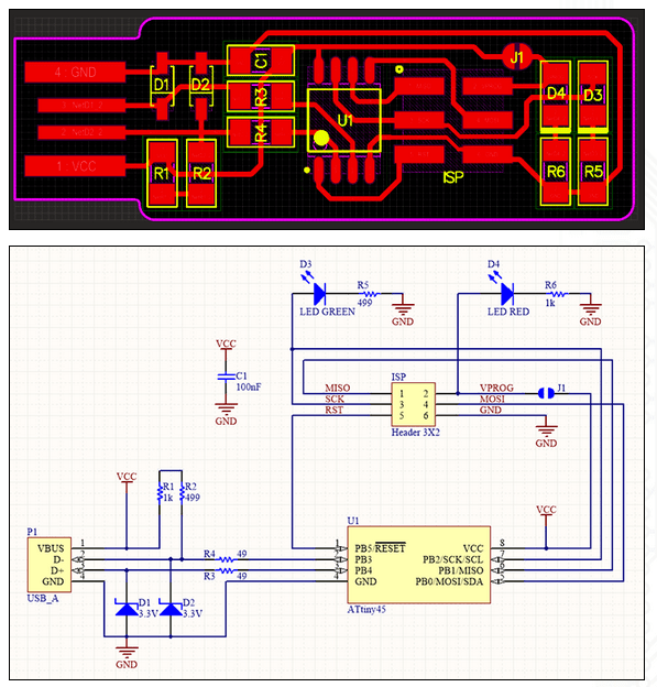
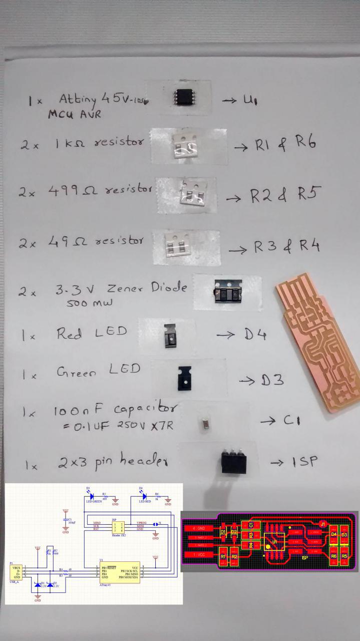
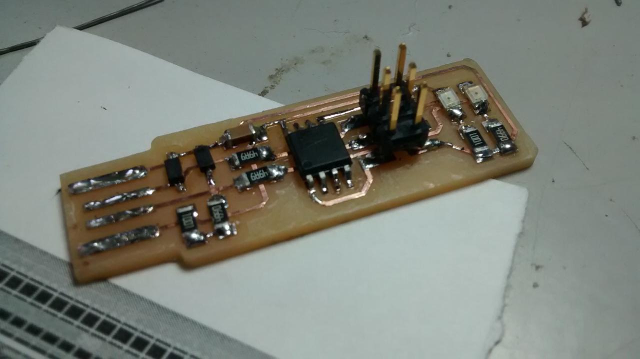
Components Used for making my ISP
Microcontroller - ATtiny45
Resistor R1 & R6 - 1 Kilo-Ohm
Resistor R2 & R5 - 499 Ohm
Resistor R3 & R4 - 49 Ohm
Zener Diode 3.3V
ISP - 2*3 PinHeader
Capacitor - 100nF
LEDs - Red & Green
Switch
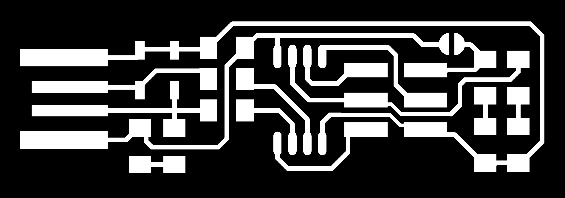
Design for Milling and Cutting
Software : Offline FabModules
Input Format : Image(.png)
Output Pocess : Roland mill(.rml)
Select Tool : PCB(1/64) - for Milling
Set Axis : Set X, Y & Z
Select Machine : MDX-20
Calculate
Sending : Send
Software : Offline FabModules
Input Format : Image(.png)
Output Pocess : Roland mill(.rml)
Select Tool : PCB(1/32) - for Cutting
Set Axis : Set X, Y & Z
Select Machine : MDX-20
Calculate
Sending : Send
Settings on Milling Machine
My USBtiny - ISP
Steps include in Flashing process
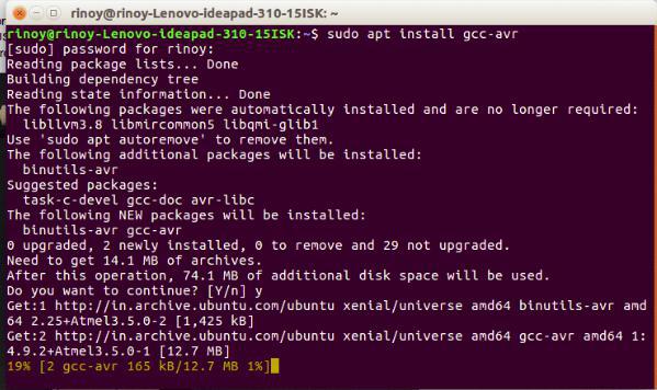
1. Install Compiler for Debugging
sudo apt install gcc-avr
2. Install Library for Compiler
sudo apt install avr-libc
3. Install flash to convert hex file to chip
sudo apt install avrdude
4. Install all functions to store in file
sudo apt install make
OR we can run on single command as shown below
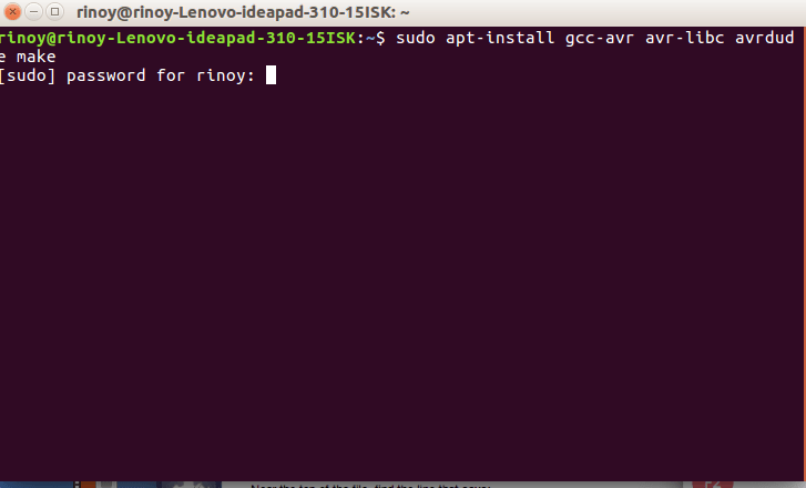
sudo apt install gcc-avr avr-libc avrdude make
EDIT PROGRAMMER ?= "usbtiny"
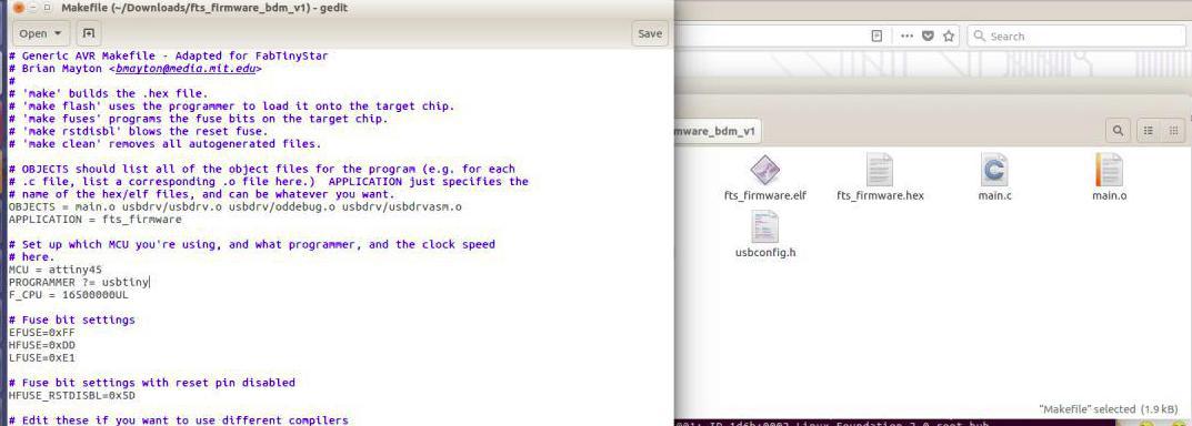
Dowload Firmware and Open Terminal from inside firmware folder
1. Converts elf to .hex file
make flash
2. Fuse certain functions
make fuses
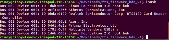
3. Search whether USB has listed
lsusb
4. Disable the RESET function
make rstdisbl
5. Confirm the USB listing
lsusb