Home
Week Fourteen : Networking and Communications
Assignment
In this week, we had to design and build a wired or wireless network connecting at least two processors
Communication betweeen two microcontroller is called Embedded Communication.Inorder to perform the communication one of the microcontroller act as a master and others to be as a slaves.Microcontroller communications may of one direction or both directions.
Two types of communication
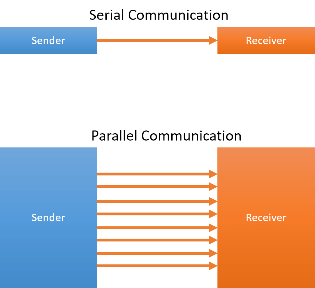
Parallel Communication
Series Communication
Parallel Communication is a method of conveying multiple binary digits (bits) simultaneously. It contrasts with serial communication, which conveys only a single bit at a time; this distinction is one way of characterizing a communications link
Parallel Communication is and always has been widely used within integrated circuits, in peripheral buses, and in memory devices such as RAM. Computer system buses, on the other hand, have evolved over time: parallel communication was commonly used in earlier system buses, whereas serial communications are prevalent in modern computers
Serial Communication is the process of sending data one bit at a time, sequentially, over a communication channel or computer bus. This is in contrast to parallel communication, where several bits are sent as a whole, on a link with several parallel channels
Serial Communication is used for all long-haul communication and most computer networks, where the cost of cable and synchronization difficulties make parallel communication impractical. Serial computer buses are becoming more common even at shorter distances
Serial data can be transferred in two modes – asynchronous and synchronous
Data Transfer is called Asynchronous when data bits are not “synchronized” with a clock line, i.e. there is no clock line at all
Synchronous data transfer is when the data bits are “synchronized” with a clock pulse
Basic principle is that data bit sampling / recording
Serial Communication Protocol
1. SPI – Serial Peripheral Interface
It is a three-wire based communication system. One wire each for Master to slave and Vice-versa, and one for clock pulses. There is an additional SS (Slave Select) line, which is mostly used when we want to send/receive data between multiple ICs
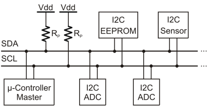
2. I2C – Inter-Integrated Circuit
I-squared-C, is a synchronous, multi-master, multi-slave, packet switched, single-ended, serial computer bus semiconductor.This is an advanced form of USART. The transmission speeds can be as high as a whopping 400KHz. The I2C bus has two wires – one for clock, and the other is the data line, which is bi-directional – this being the reason it is also sometimes (not always – there are a few conditions) called Two Wire Interface (TWI)
3. FireWire
They are high-speed buses capable of audio/video transmission. The bus contains a number of wires depending upon the port, which can be either a 4-pin one, or a 6-pin one, or an 8-pin one
4. Ethernet
Used mostly in LAN connections, the bus consists of 8 lines, or 4 Tx/Rx pairs
5. Universal serial bus (USB)
This is the most popular of all. Is used for virtually all type of connections. The bus has 4 lines: VCC, Ground, Data +ve, and Data -ve
6. RS-232 – Recommended Standard 232
The RS-232 is typically connected using a DB9 connector, which has 9 pins, out of which 5 are input, 3 are output, and one is Ground
I plan on using I2C protocol
I2C is a communication protocol which help to communicate between multiple slaves to single master chip.Like Asynchronous Serial communication it only requires two wires for communication - SCL and SDA
SCL stands for Clock Signal
SDA is the Data Signal
I2C Connection
Master - Atmega 328p
Slave - Attiny44
Connection - SDA & SLA
IR Sensor is connected to Atmega328 and LED is connected to Attiny44
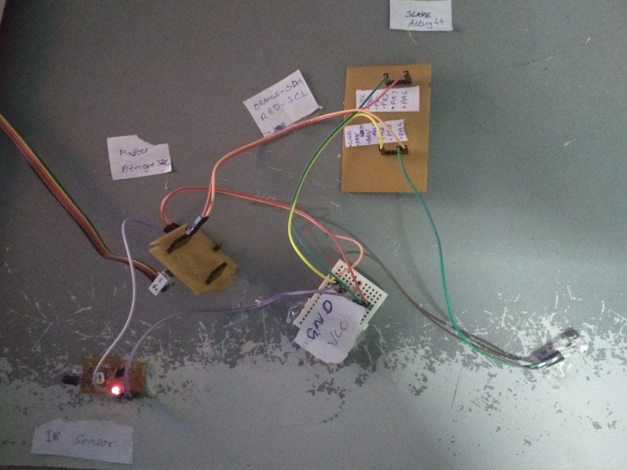
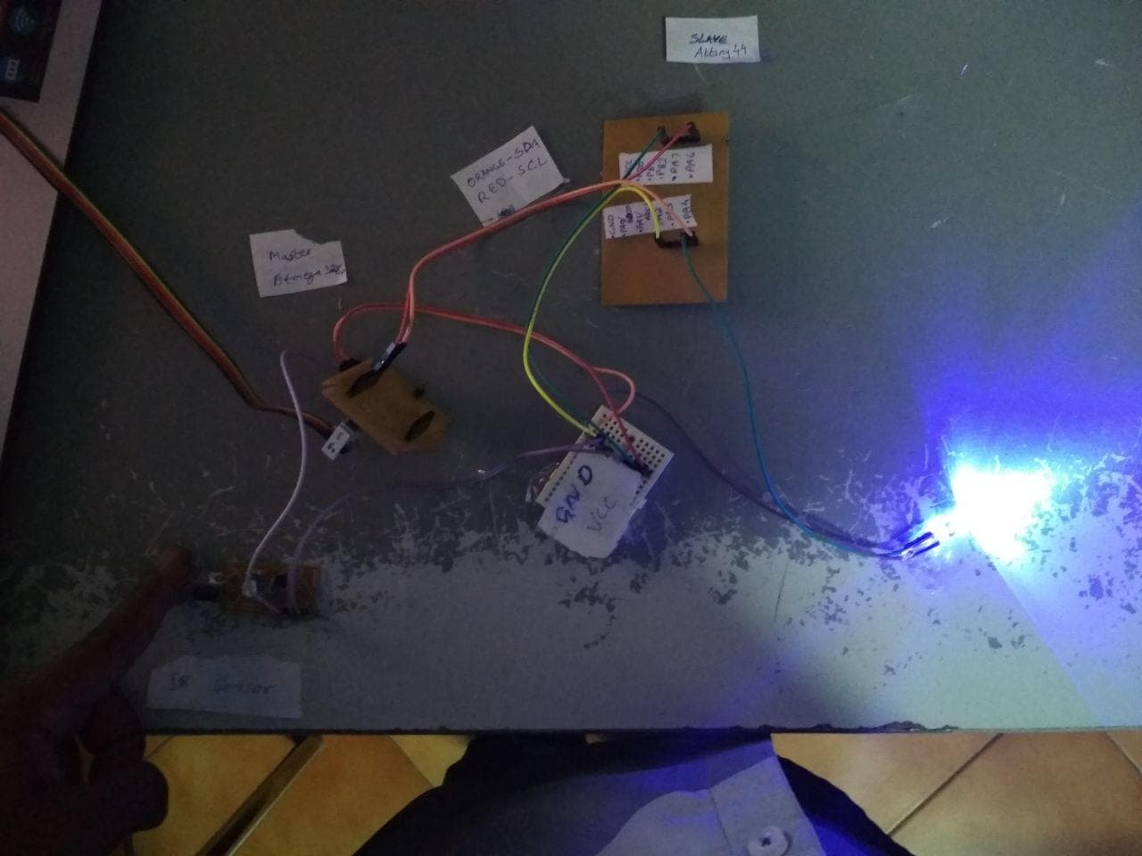
Two images given below shows two condition
1. IR Sensor - ON >> LED - OFF
1. IR Sensor - OFF >> LED - ON
I2C Connection
Connection VIDEO
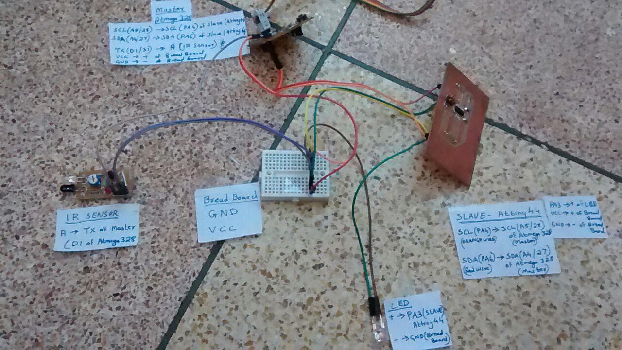
1.Master - ATMEGA328
SCL (A5/28) is connected to SCL (PA4) of Attiny44 (Slave)
SDA (A4/27) is connected to SDA (PA6) of Attiny44 (Slave)
TX (D1/31) is connected to A of IR Sensor(INPUT)
VCC to VCC of BreadBoard
GND to GND of BreadBoard
2.Slave - Attiny44
SCL (PA4) is connected to SCL (A5/28) of ATMEGA328 (Master)
SDA (PA6) is connected to SDA (A4/27) of ATMEGA328 (Master)
PA3 is connected to LED
VCC to VCC of BreadBoard
GND to GND of BreadBoard
MASTER
    #include
    int address = 2;
    int  i;
    int PIN = 1;
    void setup()
    {
      Wire.begin();
      pinMode(1, INPUT);

    }
    void loop()
    {
      Wire.requestFrom(address, 1);
      while (Wire.available())
      {
          int x=digitalRead(1);
          if(x==1)
          {
            Wire.beginTransmission(address);
          Wire.write(1);
          Wire.endTransmission();
          }
          else
          {
             Wire.beginTransmission(address);
          Wire.write(0);
          Wire.endTransmission();
          }

      }
      delay(1000);
    }
SLAVE
    #include           //the ATTiny Wire library
    int i;
    #define address 2   //this slave address
    void setup() {

      pinMode(3, OUTPUT);
      digitalWrite(4, HIGH); // software pullup
      digitalWrite(6, HIGH); // software pull up
      TinyWireS.begin(address);
    }

    void loop() {
      byte byteRc;
      if (TinyWireS.available())
      {
        byteRc = TinyWireS.receive();
        if (byteRc == 1)
        {
          digitalWrite(3, HIGH);

        }
        else if (byteRc == 0) {
          digitalWrite(3, LOW);
        }

      }
      }