Home
Week Eleven : Input Devices
Assignment
In this week, we had to add a sensor to a microcontroller and read that value
We had a brief session on sensors from our instructors
I have decided to use a IR Sensor(Infra-Red Sensor)
An infrared sensor is an electronic instrument which is used to sense certain characteristics of its surroundings by either emitting and/or detecting infrared radiation. Infrared sensors are also capable of measuring the heat being emitted by an object and detecting motion

DESIGNING
I have used EAGLE for designing PCB
I have downloaded libraries from Atmel and Fab directories. From those libraries I have added the components needed for my PCB
I wanted to make a PCB which is used for the working of both Input and Output devices.So I have decided to modify the "FabKit v.0.3-0.4"
So I chose Microcontroller - Atmega328P-AU, so I can get many ports for both input and output devices
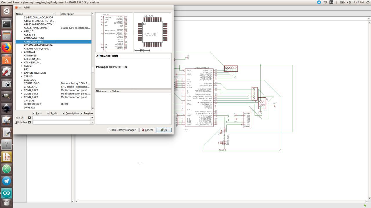
Schematic Representation
I have used Atmega328P-AU, ISP pinheader, FTDI pinheader, Switch, Resonator, Resistor and a Capacitor

Switching to Board
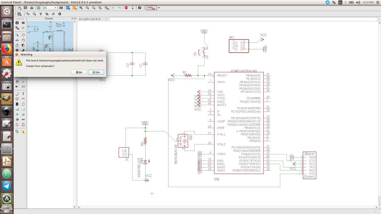
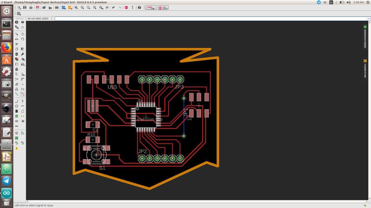
I have connected the components using "NET" and switched it to board
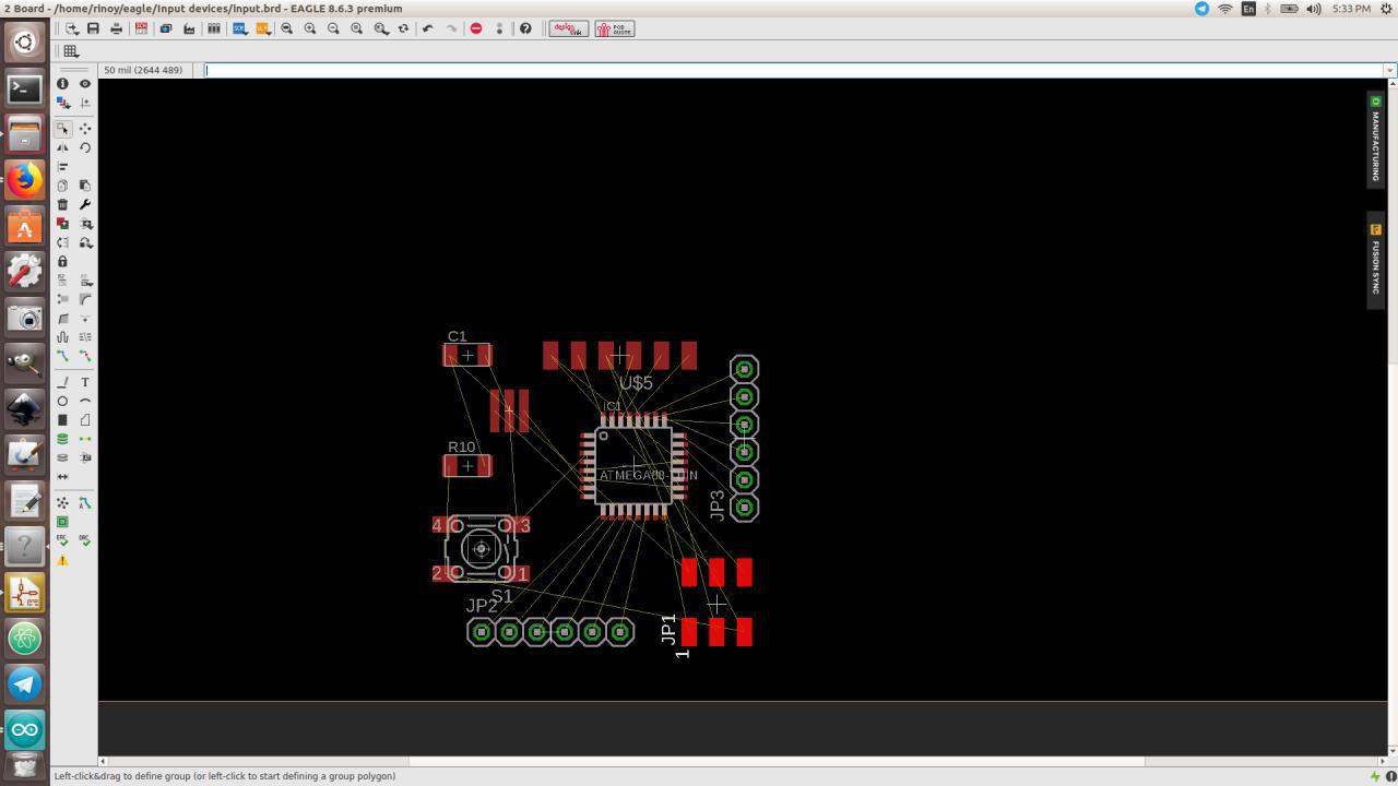
Manual Arrangement
Before Autorouting, I have manually arranged the components
Setting Design Rules
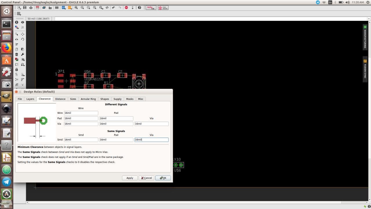
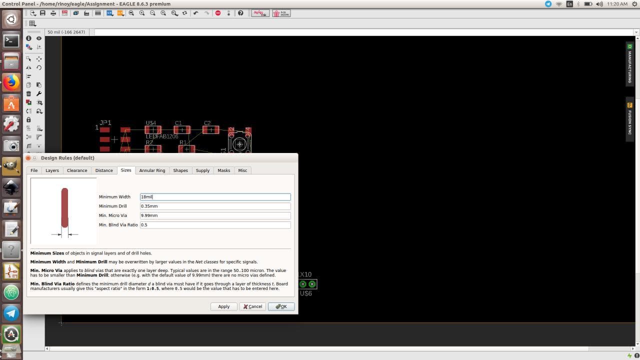
Before Autorouting, I have set the rules for Clearance and Sizes to 16 mill and 18 mill respectively
AutoRouting
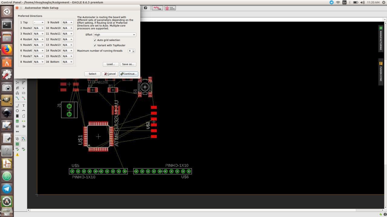
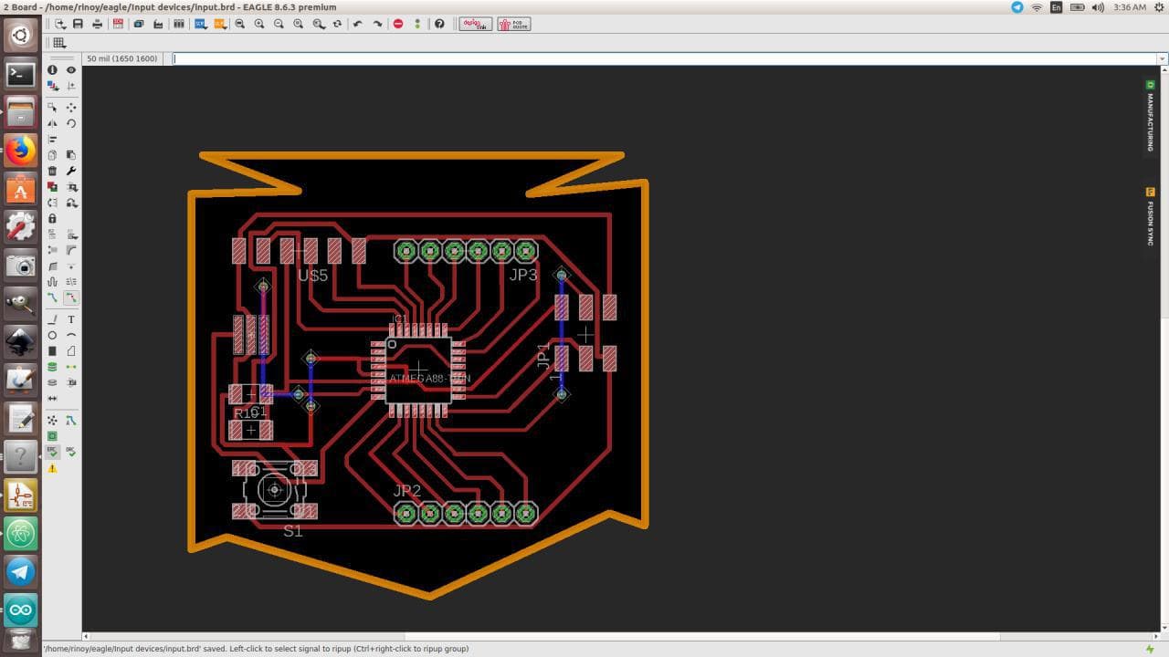
Only half of the components got autorouted, so I have routed the other half manually using "ROUTE"
Through Holes
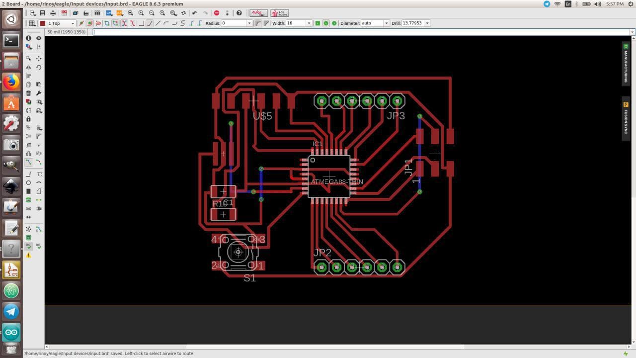
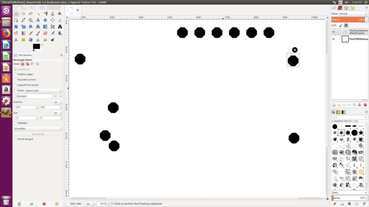
2-3 components are given through holes to get a connection
DESIGN
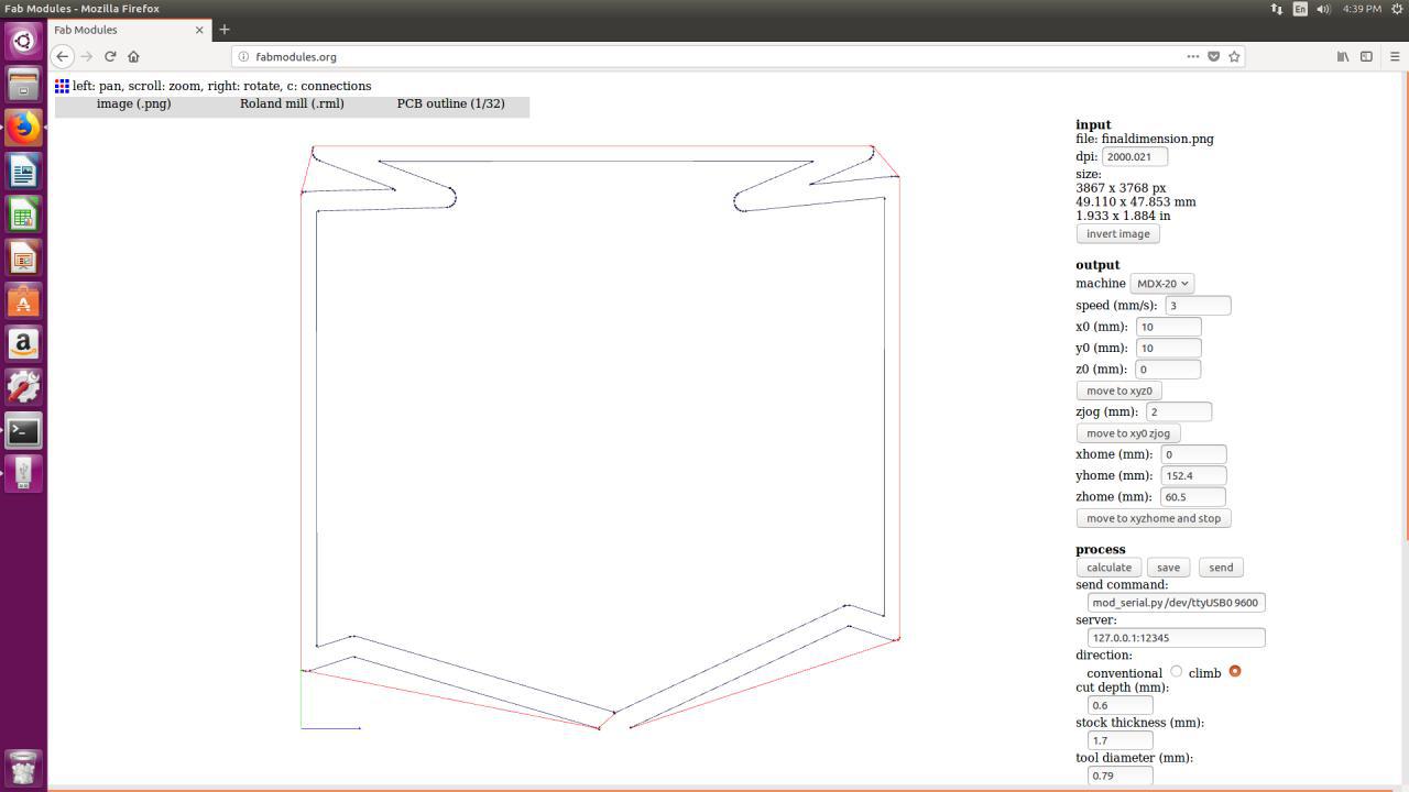
I decided to give a different shape for the border
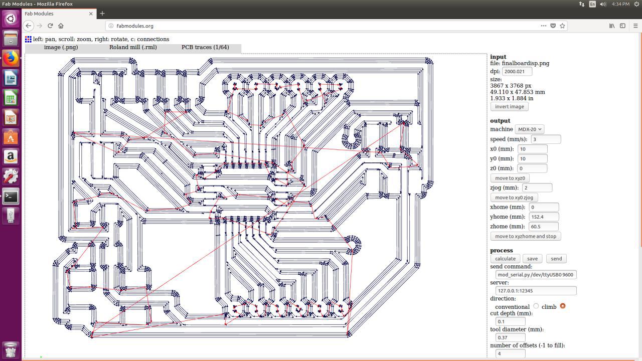
Settings on Milling Machine
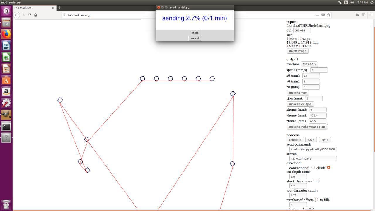
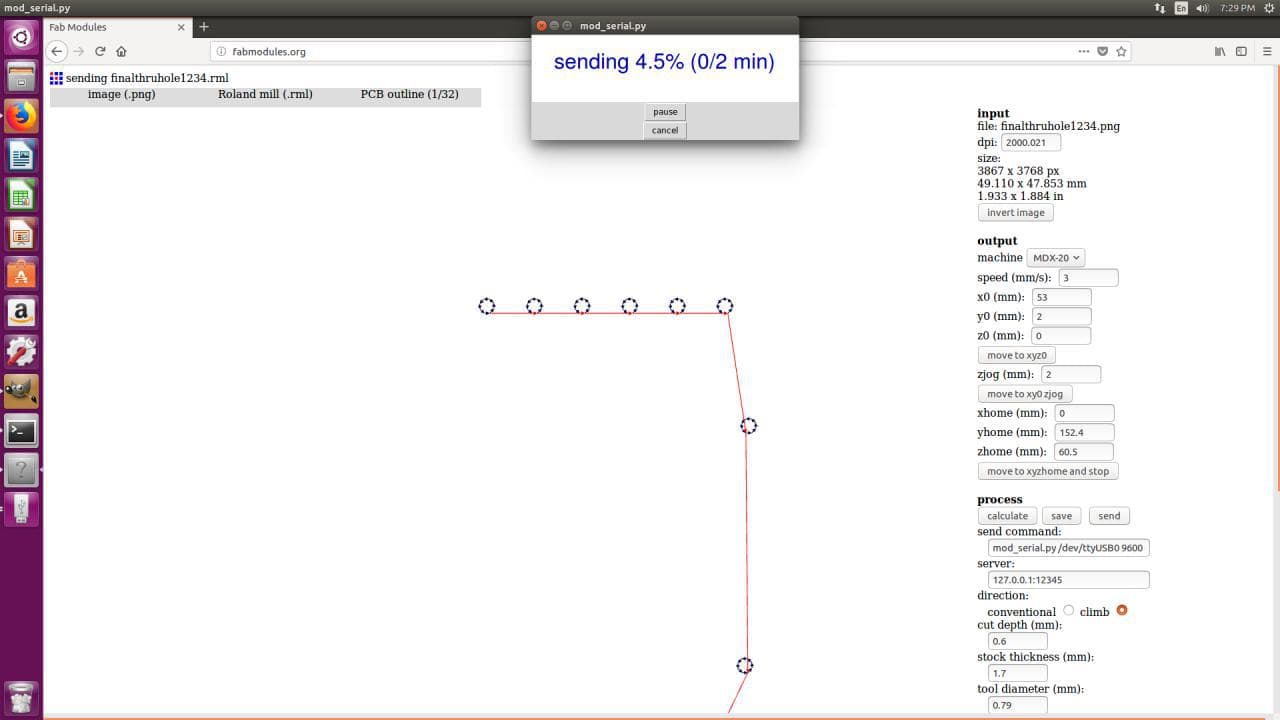
Individual settings for Traces, Dimension and for Through-Holes
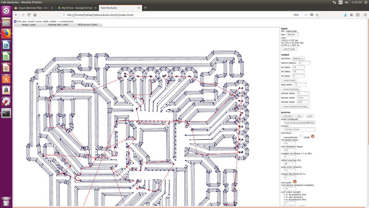
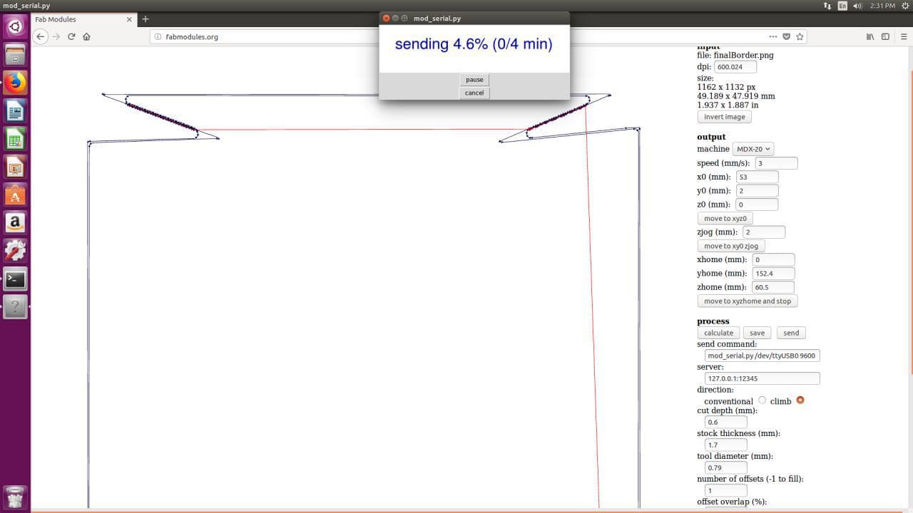
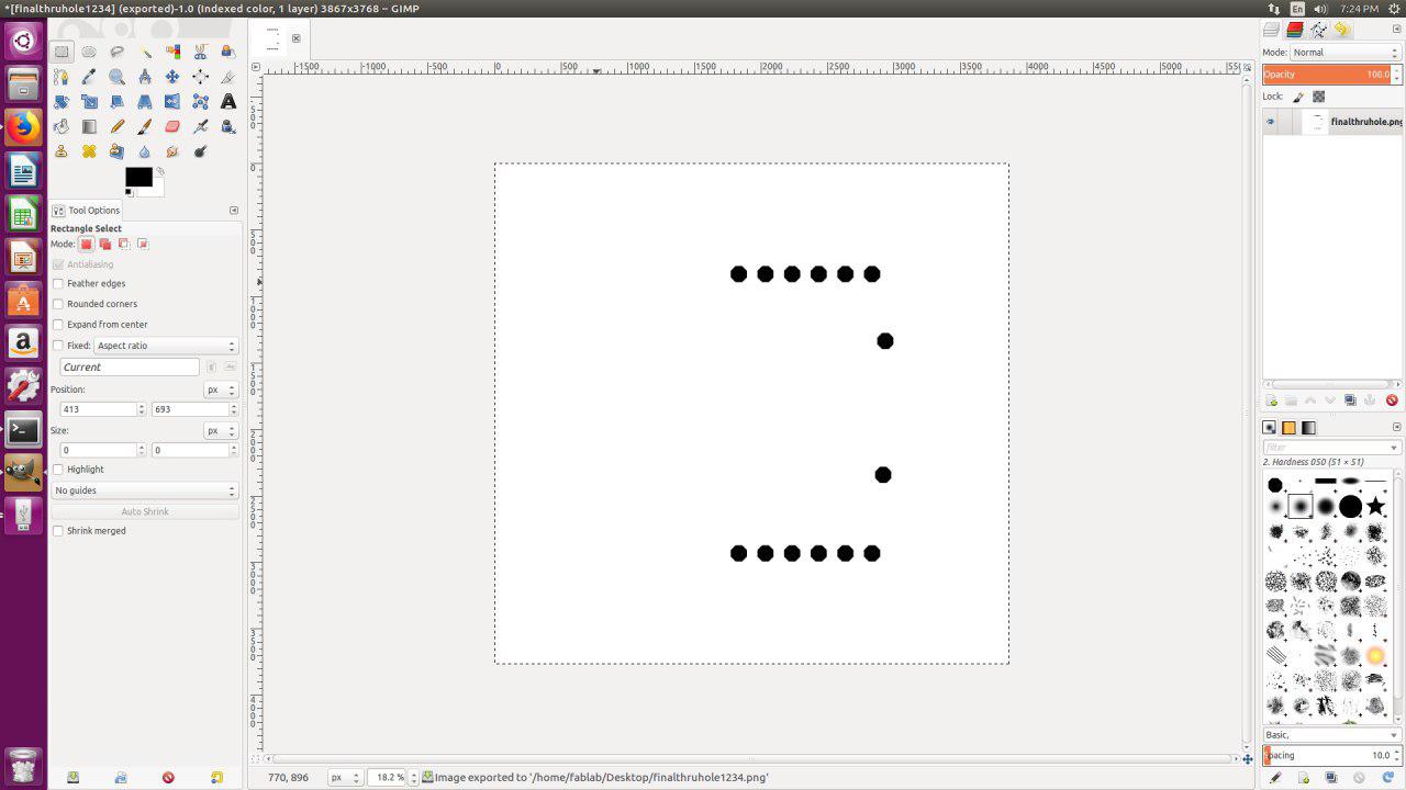
I had to use gimp inorder to Invert the image and fill colors in the holes
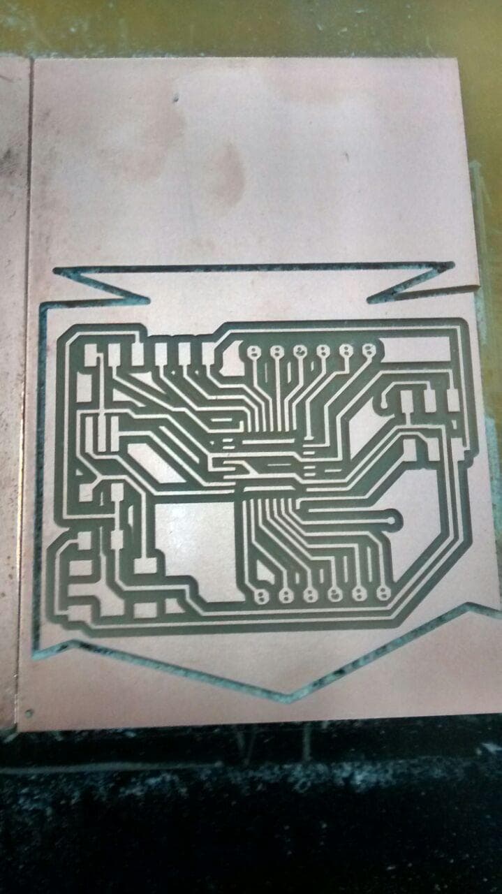
Milled PCB BOARD
Traces didnt go well
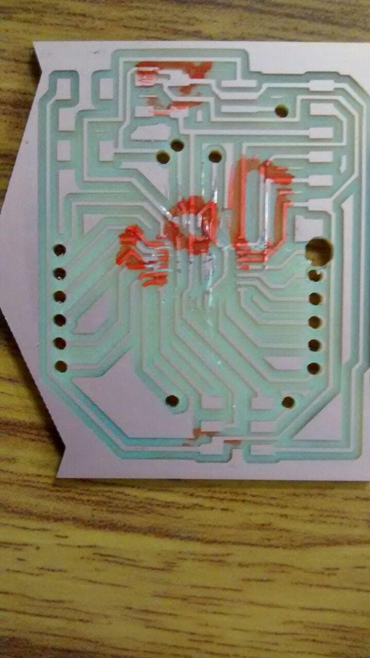
Im planning to do another design for modification of Fabkit or a simple design for Input device
RE-ARRANGED CIRCUIT
I have re-arrranged all the components and changed the design rules of sizes to 13-mill
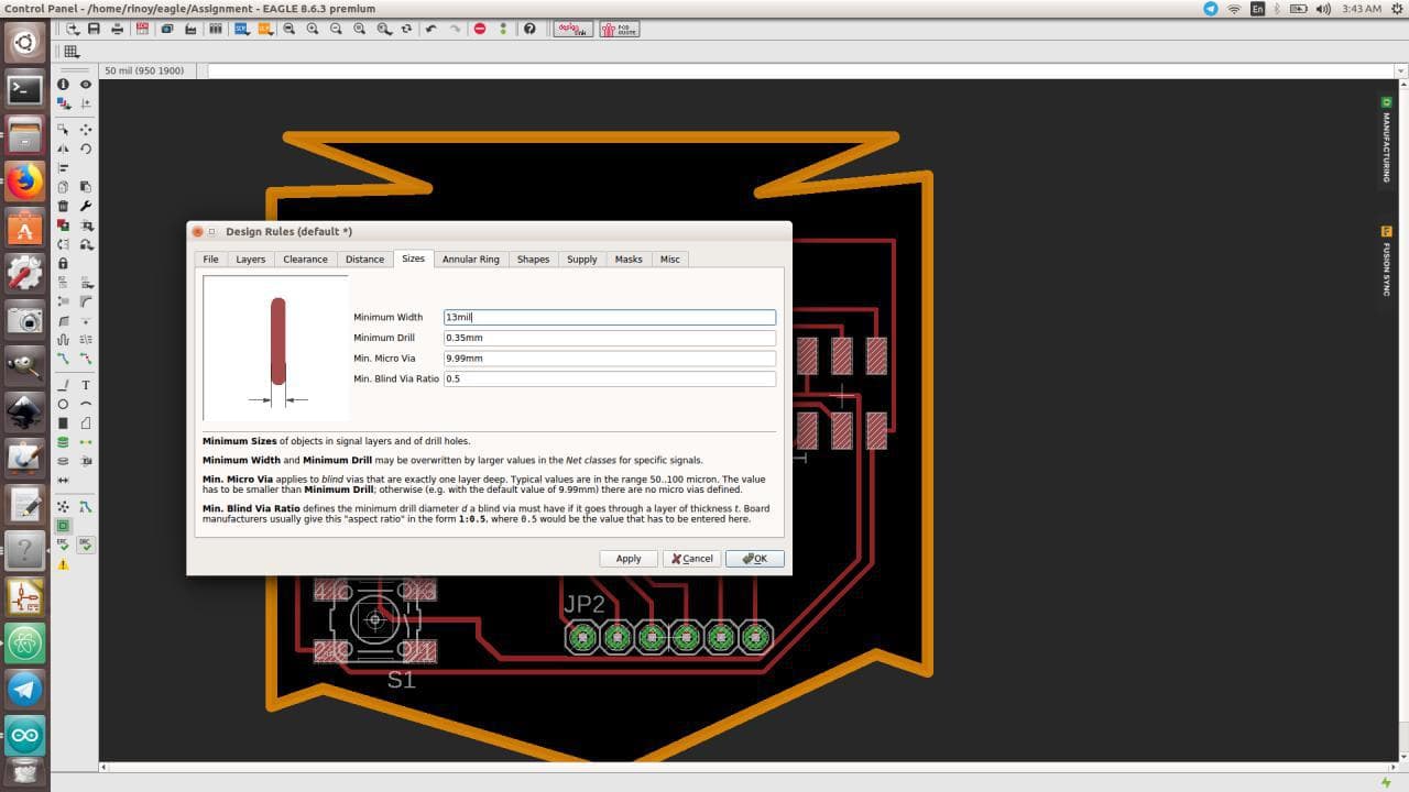
We have to individually export the "TOP layer with PADS & VIAS", "layer with PADS & VIAS" & "DIMENSION layer of the Board"
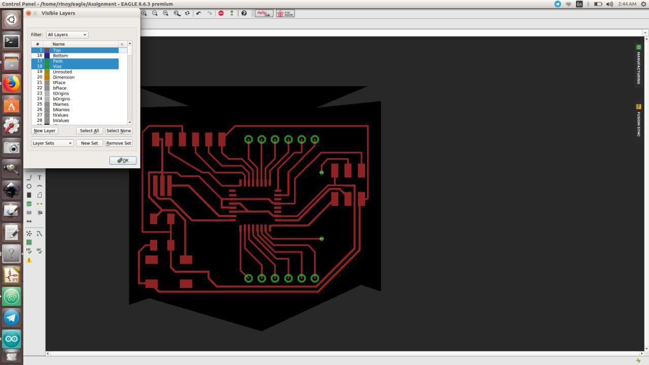
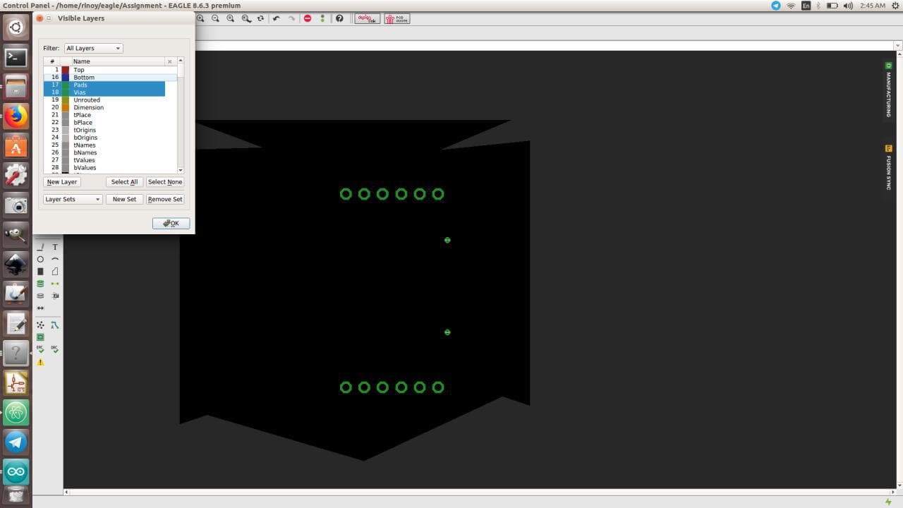
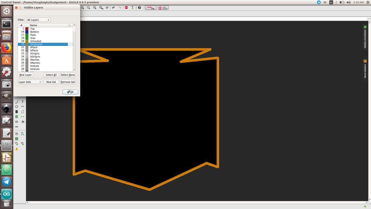
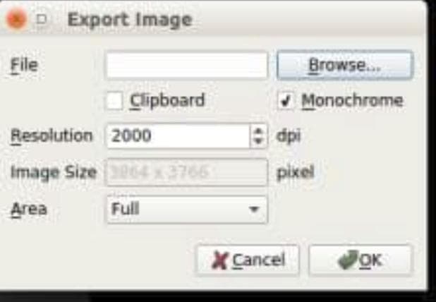
We have to Export each files with "2000 resolution" and "Monochromatic"
Pads need to be filled, as the exported files is having hollow pads.We have to fill it, so it mills completely
FINAL DESIGN
Settings on Milling Machine
Individual settings for Traces, Dimension and for Through-Holes
Milled ISP BOARD
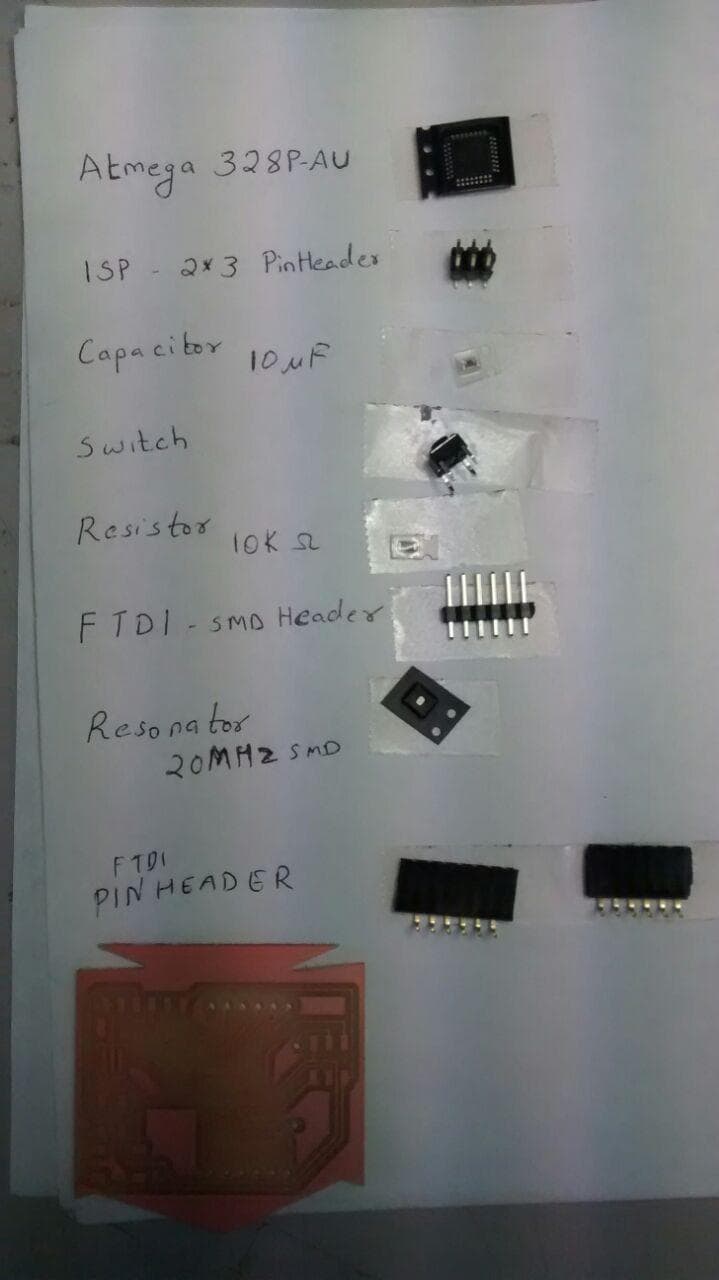
Components Used for my ISP Board
Microcontroller - Atmega328P-AU
Capacitor - 10 uF
Resistor - 10 Kilo-Ohm
Resonator - 20 MHz SMD
FTDI - PinHeader
ISP - 2*3 PinHeader
GPIO - General Purpose Input-Output Pins
Switch
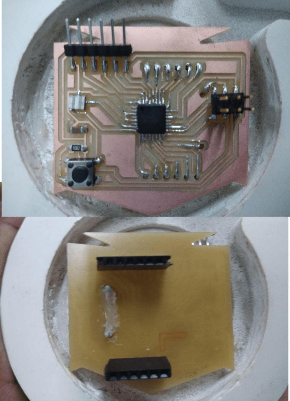
SOLDERING

ISP BOARD
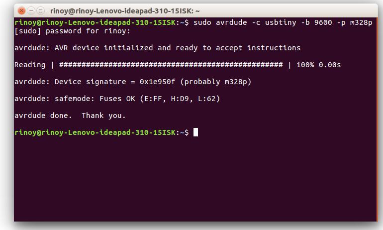
Checking My ISP BOARD
sudo avrdude -c usbtiny -b 9600 -p m328p
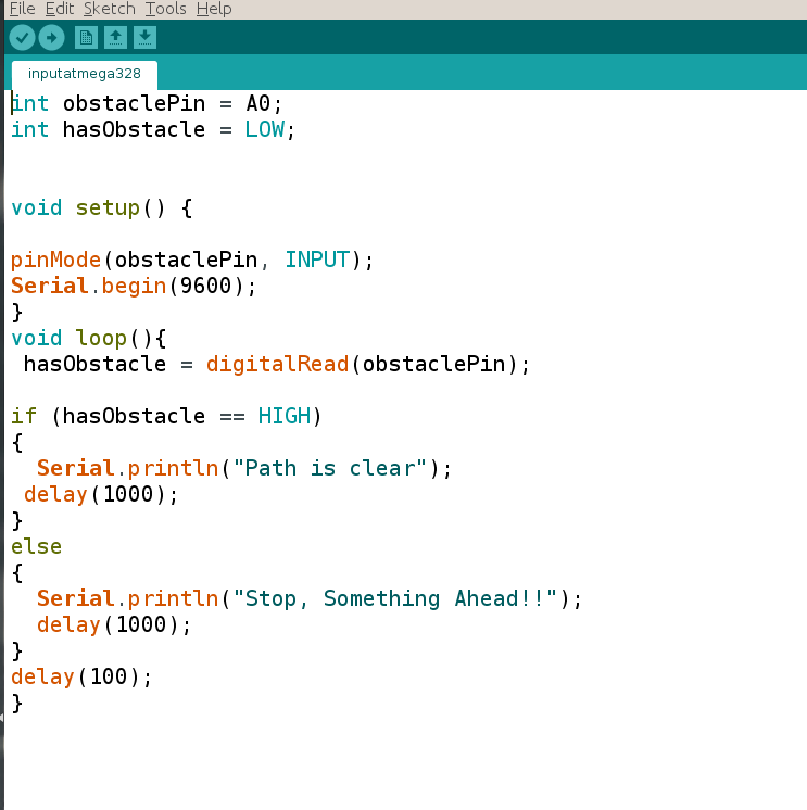
Programming Using Arduino
     int obstaclePin = A0;
     int hasObstacle = LOW;


     void setup() {

     pinMode(obstaclePin, INPUT);
     Serial.begin(9600);
     }
     void loop(){
      hasObstacle = digitalRead(obstaclePin);

     if (hasObstacle == HIGH)
     {
       Serial.println("Path is clear");
      delay(1000);
     }
     else
     {
       Serial.println("Stop, Something Ahead!!");
       delay(1000);
     }
     delay(100);
     }
Setting Board, Processor, Clock, Port, Programmer and Ports

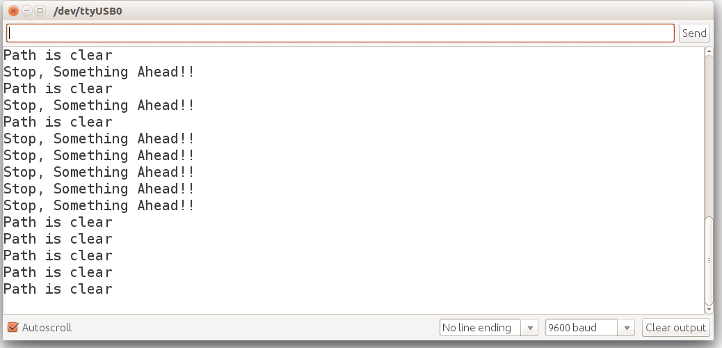
Programming Using Arduino
HEROSHOT

Video
Group Assignment
The sensor is a module or a chip that observes the changes happening in the physical world and sends the feedback to the microcontroller. Microcontroller accepts two types of input - Digital and Analog
Analog sensors sense the external parameters and given output in a range of 0 to 5V. For example, if we are using LDR sensor module. In 9.00am it gives an output of 3v and 11.00am output is 4v and 1.00pm output is 4.5v and in night output is 1v. It shows that analog sensors measure the quantity not only the presence of something
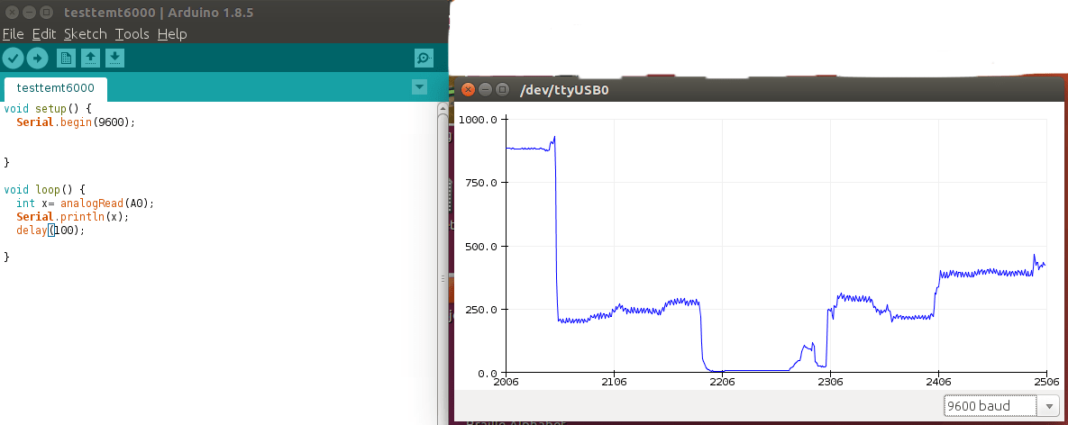
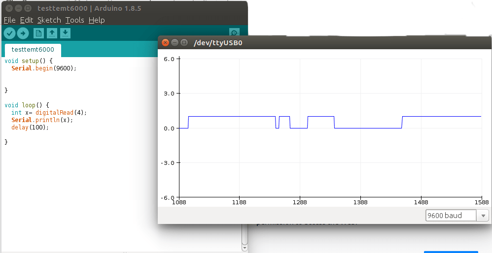
Digital Sensor produce discrete values (0 and 1). Discrete values often called digital (binary) signals in digital communication. For example, if we are using PIR sensor, It gives output of 3.3v when motion is detected and 0v were no motion detected. Here we used Arduino connected with PIR sensor and run the code and made the plot
