Week 15: Mechanical Design
Assignment: Design a machine that includes mechanism+actuation+automation and Make it
We need to make a potential machine project in these two weeks. All of them are come up with different ideas. After discussion, we plan to make a Braille printer, in which we input normal text and printer gives output in braille format. What we plan is our printer made holes( Braille script) in paper depend on the text we given as input.
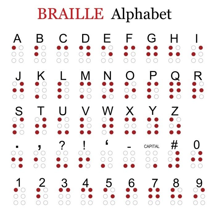
What Is Braille?
Braille is a system of raised dots that can be read with the fingers by people who are blind or who have low vision. Braille is used by thousands of people all over the world in their native languages and provides a means of literacy for all.
Details are taken from this source
Braille printer is very usefull to communicty so we ready to make this.From electrical background i dont have enough knowledge in mechanical parts and design....
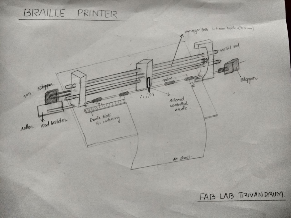
From Group discussion we got a rouf sketch how it looks like .from that we under stand what are the items we need .
- Stepper Motor - 2 nose(one for printer head movement and one for rolling the paper)
- Rod with rubber support to roll the paper
- 8mm smooth Rod for moving the head
- Driven pully and driver pully suported for GT2 betl ( Head is moving using belt)
Our main aim is to make dotes, how to make dots that only problem we are confused, then our instructor Yadhu gives the idea that using solenoid push-pull we can able to make holes in paper. Then we ordered a solenoid form online website. In the normal printer, ink injector is the head here our head is solenoid push-pull.First, we took all the components we need from fablab inventory. we don't get a rod with rubber tapping to roll the paper, so we dismount one of the damaged printer available in our lab and take the paper roller rod in that.Next, we go with making of mechanical arrangement, where to hold the stepper motor, how the head should arrange. Its create a lot of confusion. All of them are new to this field, so we don't know how to make.
After making the invneory list I draw a simple drawing in paper and Aby , design it in Fusion 360 and laser cut the part in an acrylic sheet and make the arrangement.
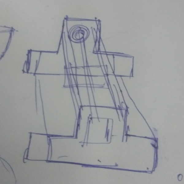
From that, we understand we need a liner bearing to hold the head and horizontal arrangement of the rod to hold head is difficult to place the solenoid push-pull so I along with Vishnu and Aby takeit as our task. I design something which makes rods for holding the head in horizontal and cut that in beach plywood place the rod and confirm that vertical arrangement is best for holding the solenoid.
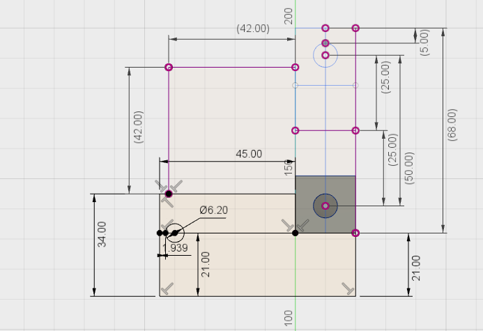
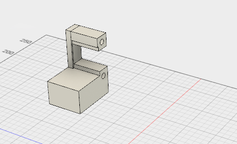
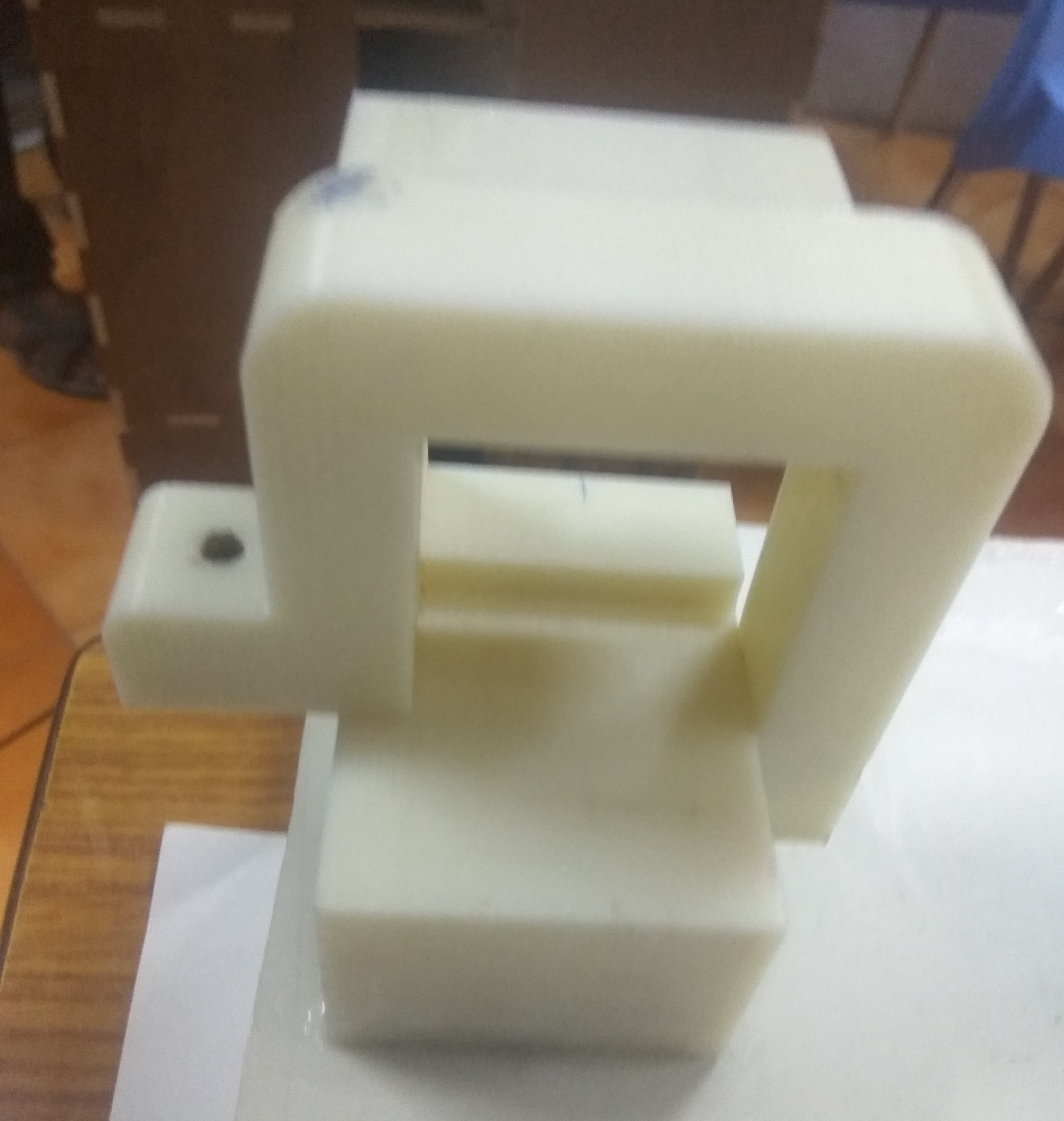
Vishnu made a small drawing in the paper, and Aby and me refer the drawing and design that in Fusion 360. For Designing we consider the dimension of Stepper motor, here we are using Nema 14 stepper motor which dimension is 42mmx42mmx42mm. We arrange the rod for carrying head is in a vertical position and center to center distance is 50mm. One side of the design we made a pocket to hold the roller motor stiff.
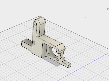
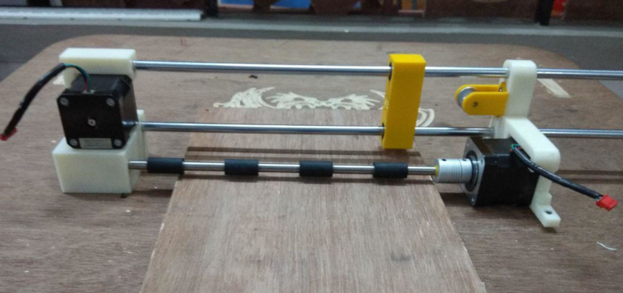
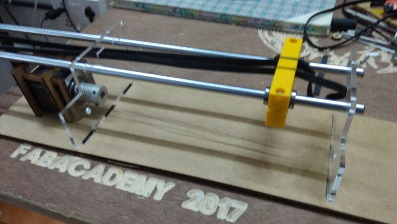
After completing the design we export the STL files and 3D printed in Dimension.It takes around 15 hours to complete.After finishing the 3D printing I along with Rinoy , and Akhil arrange it with rods and roller also place stepper motor in respective position . Hence we realize that while design i made some mistakes.I forgot to add supports for holding the stepper motor which drives the x- axis. I designed that in fusion and again 3D printed it in Dimension .After that our project looks more Rigid.
We forgot to give driven pully holder in right side motor holder, and Left side motor does not have support to fix that, with our support the motor may displace the position.Akhil made the driven pulley holder and we screw that on the left part and Akhila made the Head connector.
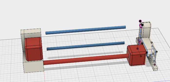
After that, we place the motor corresponding positions- Head is controller by stepper one which placed a little height and paper roller rod connected to Stepper 2 all of them made all the arrangement as teamwork. After placing the motor, we connect GT2 Belt with pulley, and our mechanical arrangement finished.
But we are still missing a motor holder for the head, so I designed it and printed that in dimension. after we Stick it with other model using Fevistick .it good additive glue which helped to make a strong bond so that we cant separate it out.
Finally, our mechanical design of Project is over. Now I lear couple new things like how to make mechanical designs. Next steps actuation, we all are new to this so little bit anxiety among all, but we have confidence in our mind we can make it.Our Machine week