PCB fabrication for the FabTinyISP
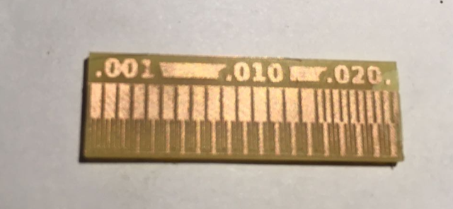
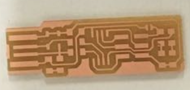
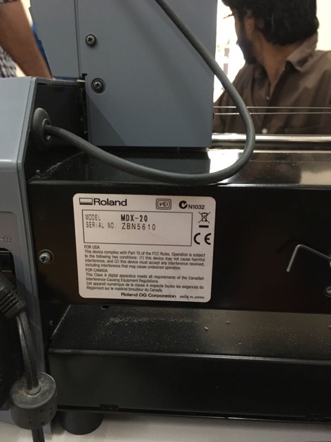
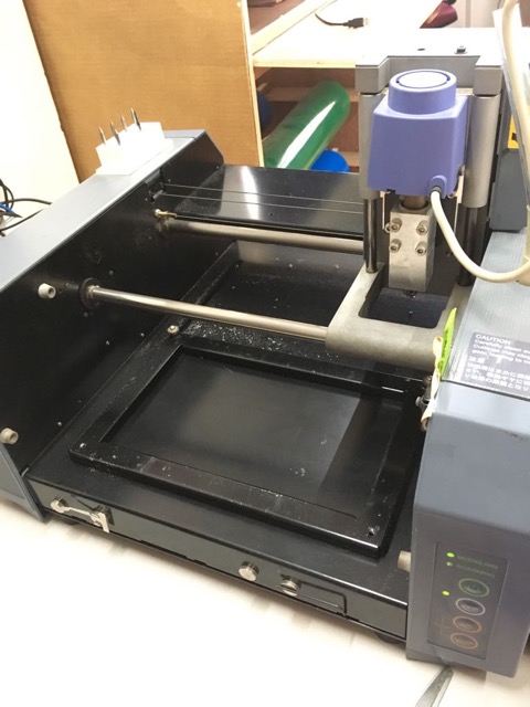
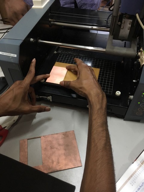
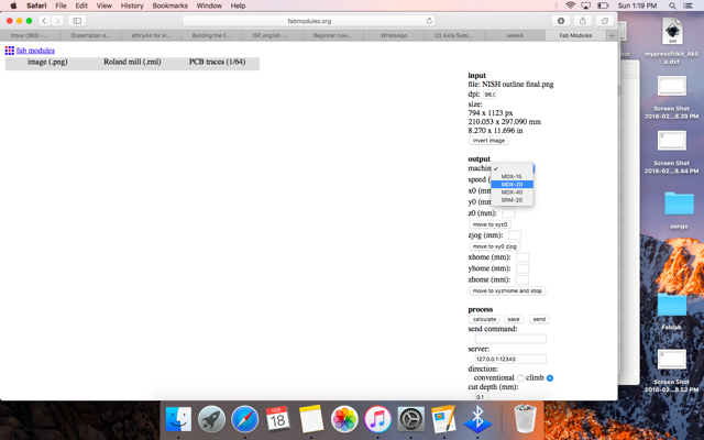
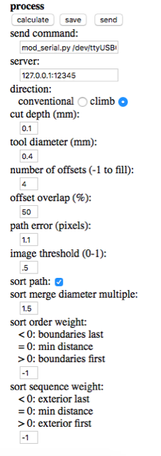
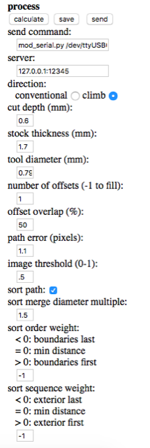
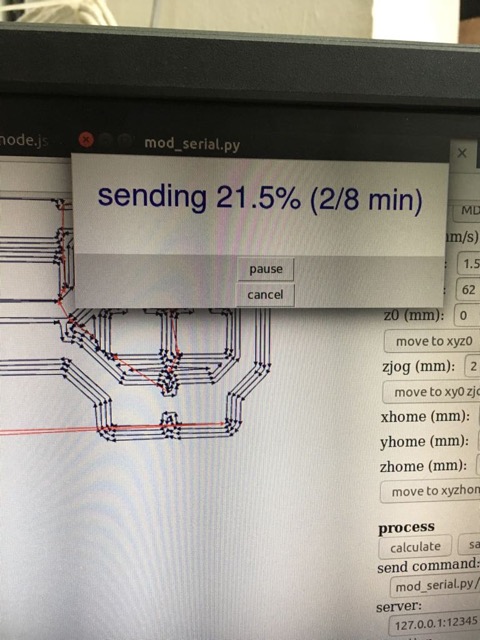
The same process as described above was followed for our individual assignment to mill the PCB for the FabTinyISP, following Brian's tutorial.
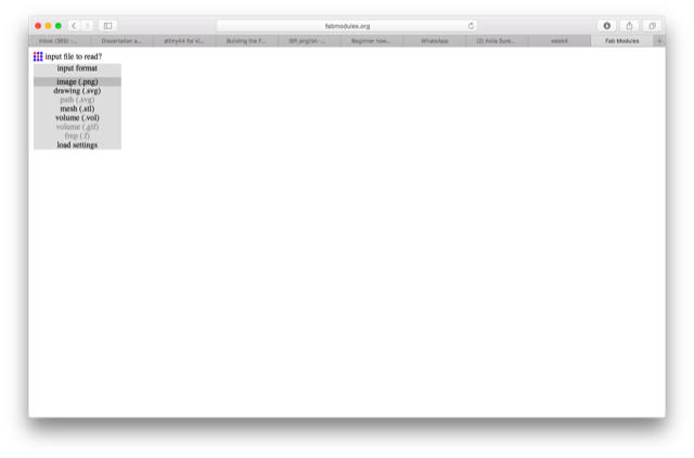
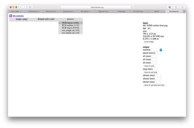
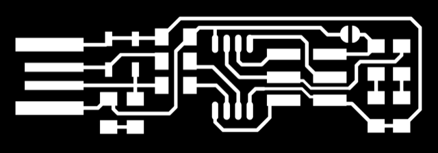
The image file was downloaded from Brian's tutorial 'Building the FabTinyISP'.
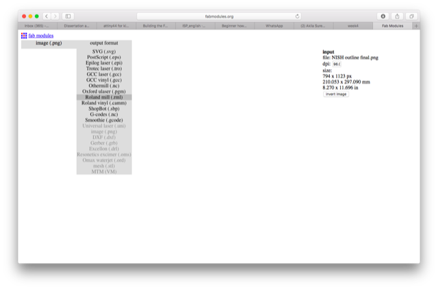
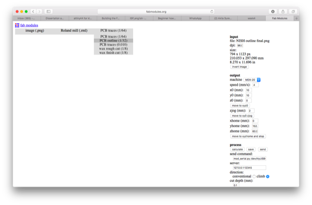
This is the outline image for cutting, also taken from Brian's webpage.
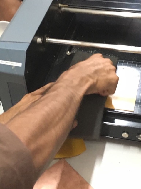
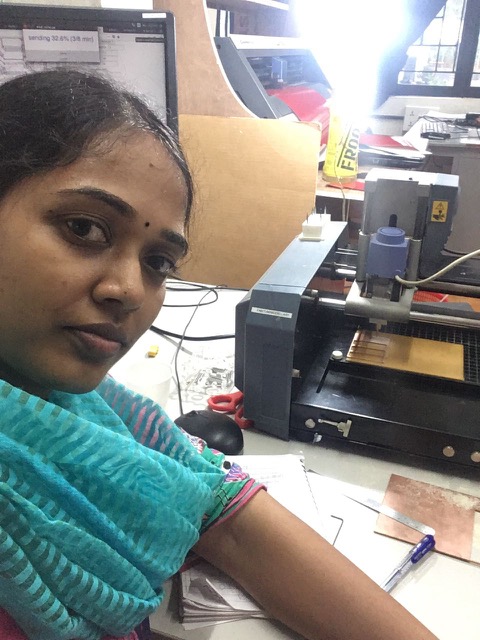
A selfie while the machine is milling. Check the video at the top of this page for the video record.
Soldering and assembling the PCB
Soldering seemed very difficult at the first go but got easier and was even fun, once I got the hang of it. The trick is to heat the board with the soldering rod and place the lead on it. As the lead melts, place the component in the required orientation with the tweezers. Use the soldering rod again to smoothen the soldering.
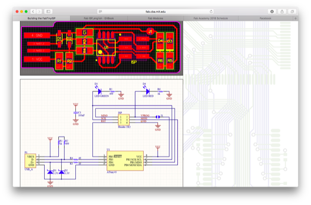
These are the images from Brian's page that we used to select and solder the components at the appropriate positions and orientation on the PCB.
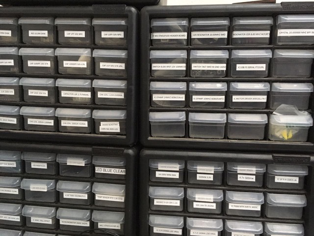
Picking the required electronic components from these arrays of little drawers felt like shopping for items on a recipe ;).
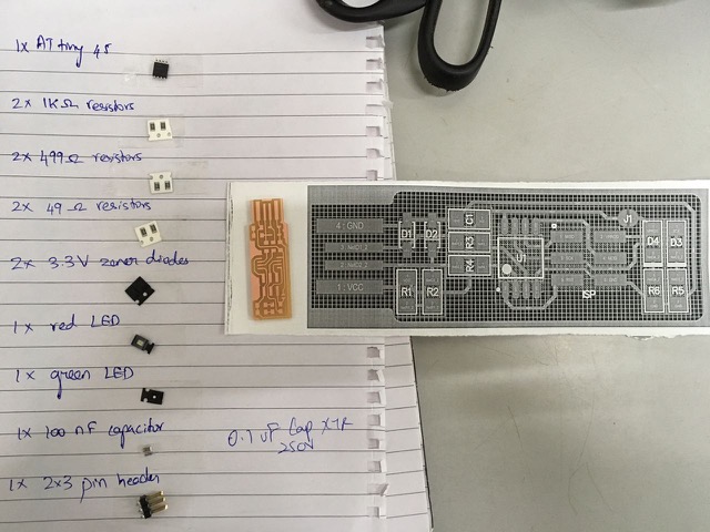
The required items have been picked and pasted on a paper to easily retrieve for soldering.
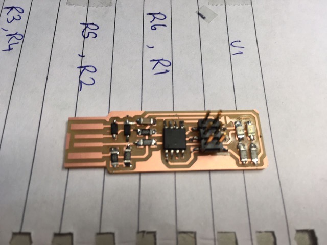
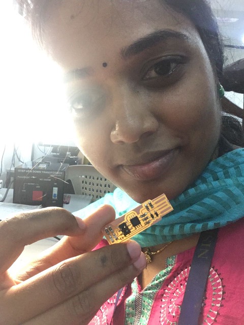
The end result after soldering. Check the video at the top of the page for the action.
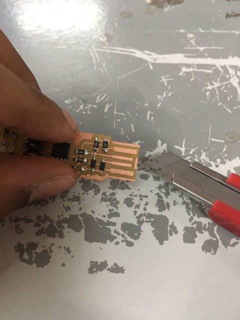
The extra copper in the front of the pad is removed with a pen-knife.
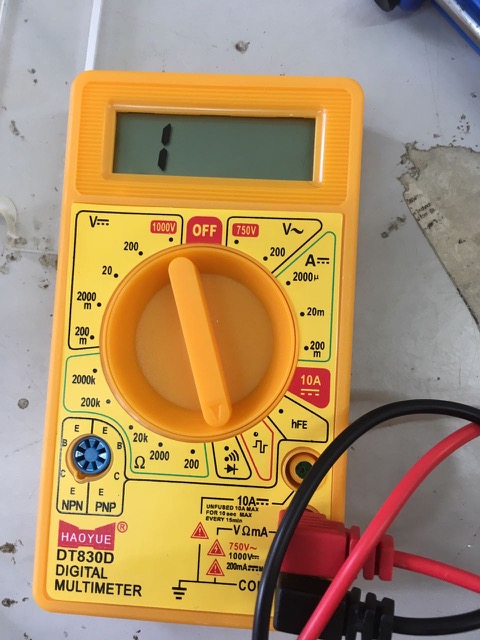
I used the multimeter to check that the circuit is connected and all the solder joints are in place. The black and red ends of the multimeter were placed at two different points in the circuit. If the circuit was complete, the values would change and a long beep would be heard. The video clip of this can be seen towards the end of the video at the top of the page.
My circuit seemed to be intact when checked with the multimeter. However, when the PCB was plugged into the PC, both the red and green LEDs lit up. This is a bug as only the red LED should light up now. The green LED should light up only when the programme is loaded into the PCB.
Vinod, our instructor, helped me by checking the circuit with the multimeter again. He noticed that the forward bias voltage value across the two diodes D1 and D2 was over 700V on my PCB whereas it was ~650V in the other functional PCBs.We tried changing the diodes - didn't work. Then Vinod removed the IC and noticed that one half of the IC (3 pins) had not been soldered completely. He soldered it back and then the problem was solved! I wondered then why the multimeter debugging had not revealed this issue. Vinod said that the pressure applied by the multimeter pin would have pressed the IC down and completed the circuit. When the multimeter was taken off, the circuit would have been incomplete. This was quite an eye-opener.
Programming the PCB
I connected my PCB to our instructor, Yadu's programmer, such that the same connecting wire connected the first pin of one board with the other (check the video at the top of this page). The programmer was inserted into my PC. I had downloaded 'Crosspack' on my Macbook. I also downloaded the firmware source code, as per the instructions on Brian's tutorial. I didn't have to edit 'Makefile' as it already had the line
PROGRAMMER ?= usbtiny
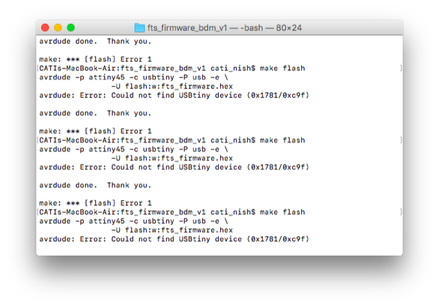
1. I opened the terminal from within the firmware source code folder and typed in 'make flash'. However, it displayed an error message :' Could not find USBtiny device'. This issue was resolved when I used another programmer which fitted more tightly into the PC's USB port.
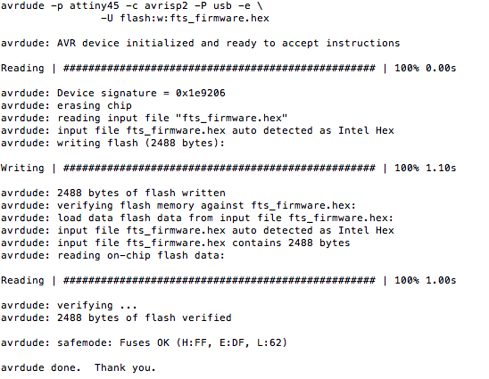
2. 'make flash' command to erase the chip and flash it with the new hex file was processed successfully.
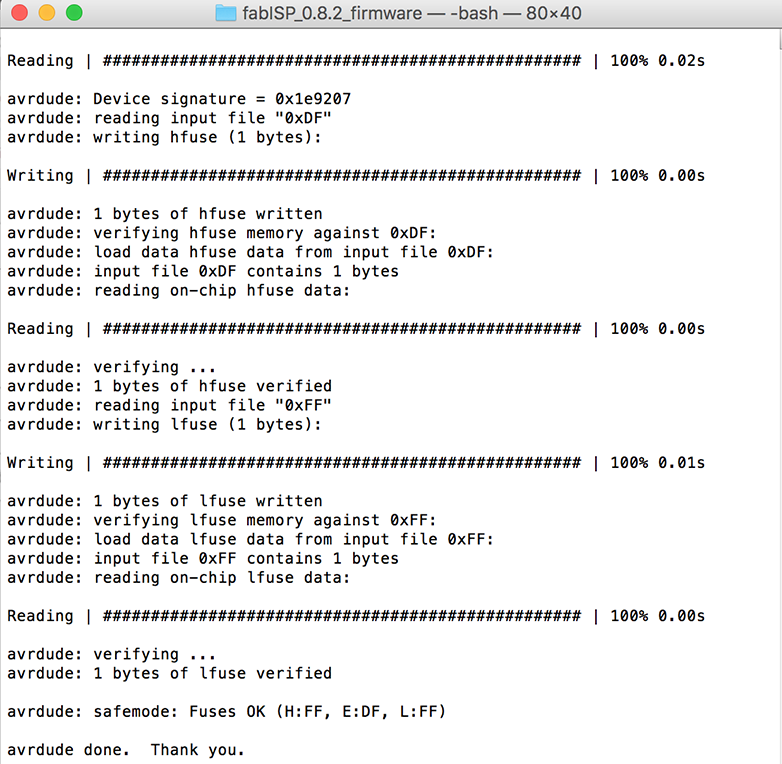
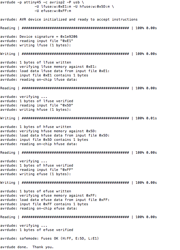
3. 'make fuse' command to set the configuration fuses was processed successfully.
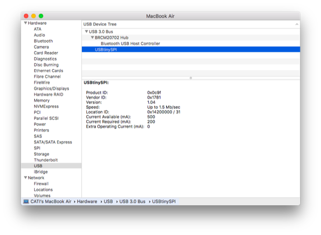
4. Plug in the PCB directly into the PC. In 'About this Mac>System Report' the details regarding the 'USB' were displayed. As per Brian's tutorial, this implies that the PCB is now programmed.
5. Connect the PCB to the programmer again and connect the programmer to the PC. In Terminal, enter 'make rstdisbl' to disable the 'reset' function in the PCB, so that it can now be used as a programmer.
 Group assignment: