Tuesday morning - I have spent the week in trying the 'serial bus'. I also read some theory on I2C and intend to try it as well. So far, I could only succeed in making 2 boards talk to each other by serial communication. Here are the program files (.ino) for master (board with the switch) and the slave (board for the motor).
I wanted to emulate Neil's example of 'serial bus' with my own boards. But Yadu asked me to do it differently. In Neil's example, he uses a 'bridge' board. The PC is more like the 'master'. I'm trying to use one of my boards as the 'master' and the other two as 'slaves'. However, I have not succeeded in that yet.
The three boards that I have are - the temperature sensor, the echo hello world board with the switch and LED and the bipolar stepper motor board. I have been trying to configure a serial bus where the LED (on the echo board) will flash if the temperature went below a certain threshold and the bipolar motor will start rotating if the temperature went above.
These are the program files (.ino) that I'm still playing around with : master (temperature sensor .C file from Neil's input devices example), slave1 (LED), slave2 (bipolar motor). I borrowed the calculations for the temperature from the ADCL and ADCH data on the sensor from Neil's Python GUI file for the sensor.
Currently, the motor is rotating, whatever the data it receives from the sensor. It is not going by the IF-condition in the code. I wonder why??? Is the data being received correctly from the sensor? I'm just flummoxed and hope to resolve it tomorrow in the lab with the help of mentor. Also planning to try I2C after debugging this one.
I have not solved the above problem yet. I'm moving on to explaining how I used the I2C networking protocol for my final project.
I2C networking protocol
For my final project, I made a 'head-controlled mouse', in which the MPU6050 accelerometer-gyroscope sensor communicates with the chip ATmega32U4 using the I2C networking protocol. For this, we need just two wires for communication - SDA (Serial Data) and SCL (Serial Clock). SCL is used by the Master to generate the clock for the communication.
(1)Electronics design
I chose to use ATmega32U4 on my board because its firmware complies with Universal Serial Bus (USB) specification and hence when the it is plugged in via USB cable to a computer, the board will be recognized as a USB device.
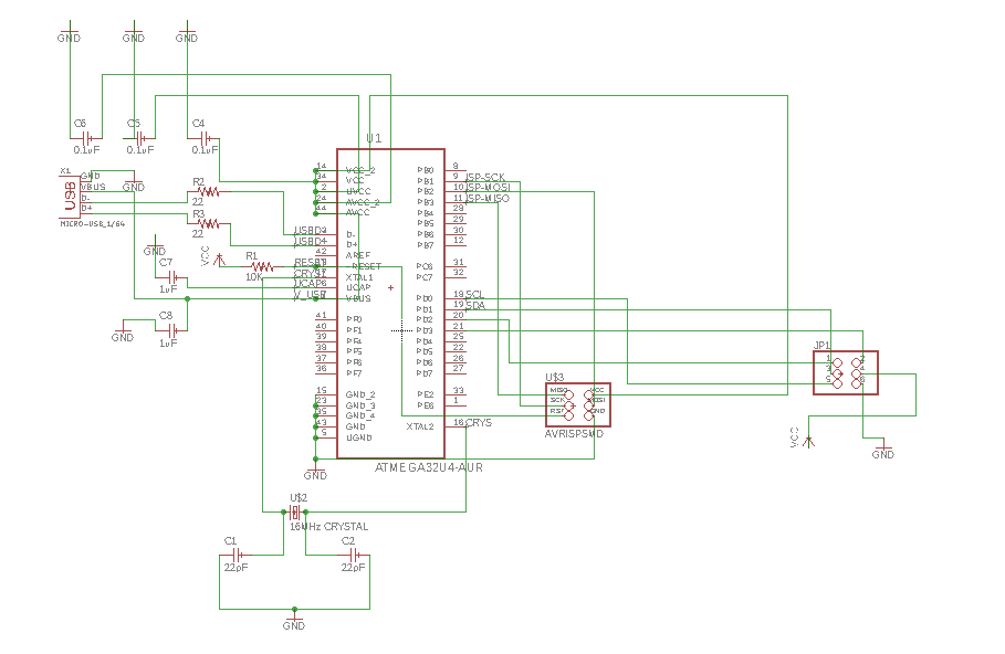
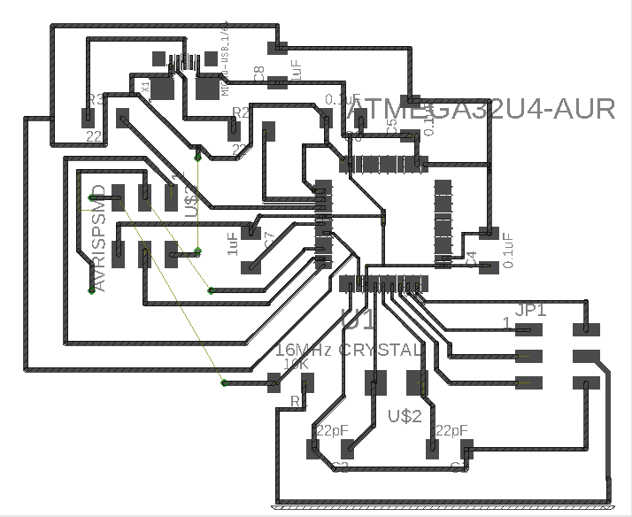
Here are the design files : schematic and board.
This time, I designed the circuit entirely on my own and it felt so good. The circuit only has the following bare essential components in it:
1. Reset pin of ATmega32U4 chip connected to 10K ohm resistor, which is connected to Vcc.
2. UCAP pin of ATmega32U4 connected to 1uF capacitor, which is grounded.
3. 0.1uF coupling capacitors between the various Vcc and Gnd pins of the chip. It is important to place the capacitors physically close to the chip.
4. ISP connections - SCK, MISO, MOSI, RST, Gnd and Vcc.
5. I used a 6-pin header to take out SCL, SDA, Vcc and Gnd connections for the MPU6050 sensor. The last 2 pins are connected to Rx and Tx pins of the chip, since I'm planning to try bluetooth communication later.
6. 16Mhz crystal with a pair of 22pF capacitors. (However, I shifted to using an 8Mhz oscillator later, as I will be explaining below).
7. USB female plug - 4 terminals connected to Vcc, Gnd, D- and D+ pins of the chip.
I autorouted first to get some idea and then manually edited and re-routed the circuit. This was a good experience.
(2)Electronics production
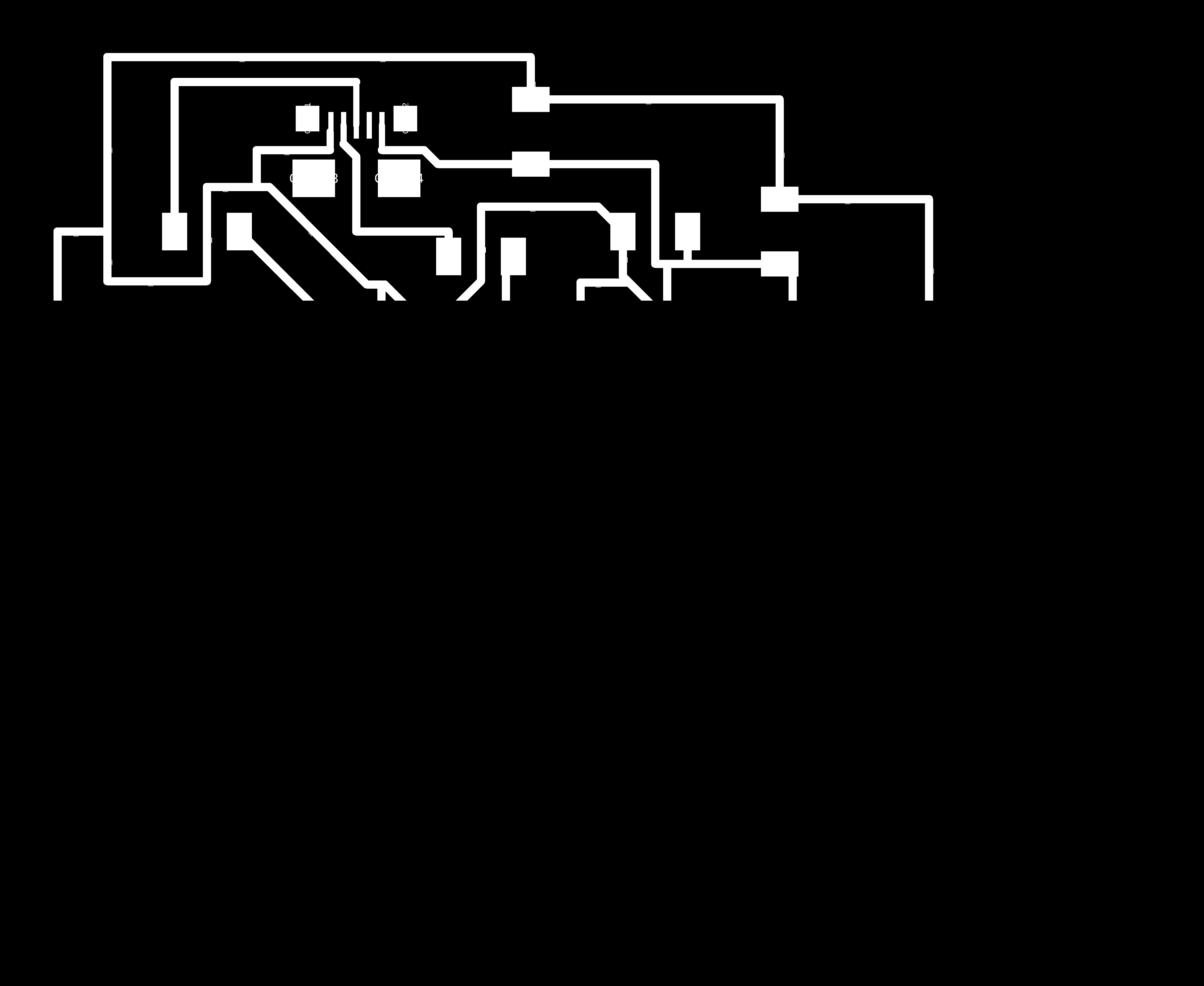
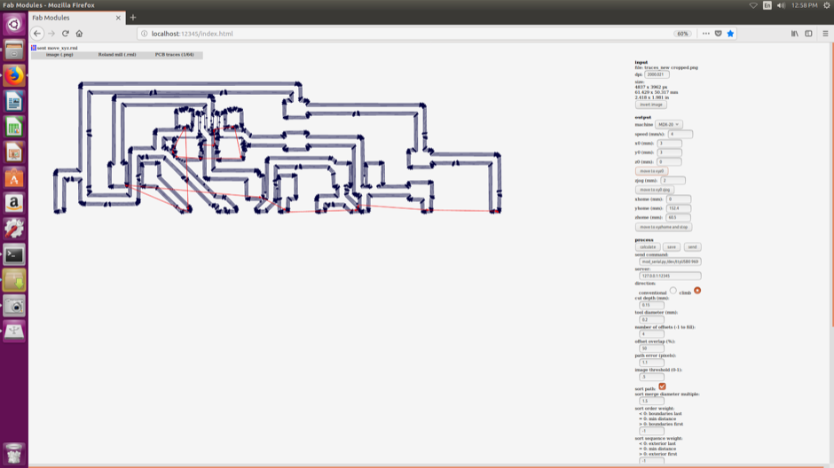
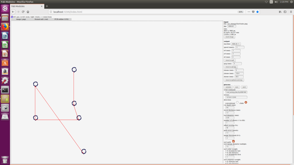
The following are the images of the traces to be milled in Roland MDX-20 machine. The machine bed must have had some specks of dirt sticking on it. The top portion of the board didn't get milled deep enough, when compared to the rest of the board. Hence I used GIMP to crop the traces, set the z-axis near the top of the board and milled again, but only along the cropped region. This was partly successful. The traces got milled to the right depth. However, the copper at the bottom edges of the cropped region got cut. I have to solder and redo the connections.
I had to add drill holes for 3 jumper wires. I should use the zero ohm resistor trick next time.

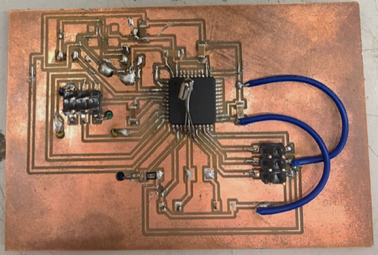
This is the board with the 16MHz crystal. There has been another error - the pad for the USB female plug is too small for the component that we have in our lab. Upon Yadu's suggestion, I decided to cut the USB cable and directly solder the four wires into the circuit. This was easier said than done, which I realized later.

I tried to check the fuses with the above board. The board was not getting recognized. Lancy suggested that replacing the 16MHz crystal with a resonator might work (I don't understand the reason.). He helped me solder an 8MHz crystal precariously on top of the chip! Strangely, the board got detected now and the fuses were ok.
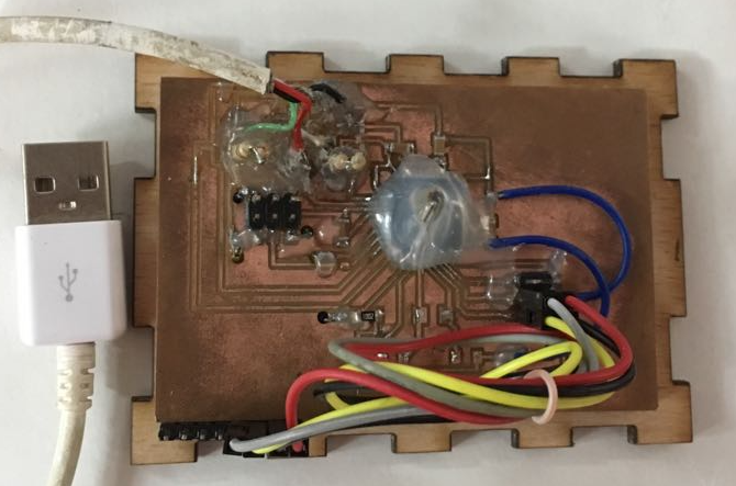
Pic below after soldering the USB wires and connecting the MPU6050 (stuck under the board). Vinod helped me with soldering the USB wires, which was very tricky to do without short-circuiting.
(3)Embedded programming
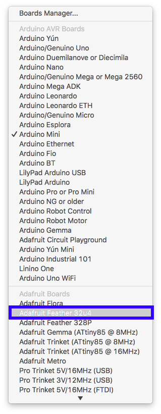
To set the clock and board in Arduino IDE, I had to look for a commercial arduino board with the ATmega32U4 chip and 8MHz resonator/crystal. I found one called 'Adafruit Feather 32U4'. After choosing this board and the programmer, 'Burn Bootloader', followed by 'Upload using programmer' to flash the programme into the chip.
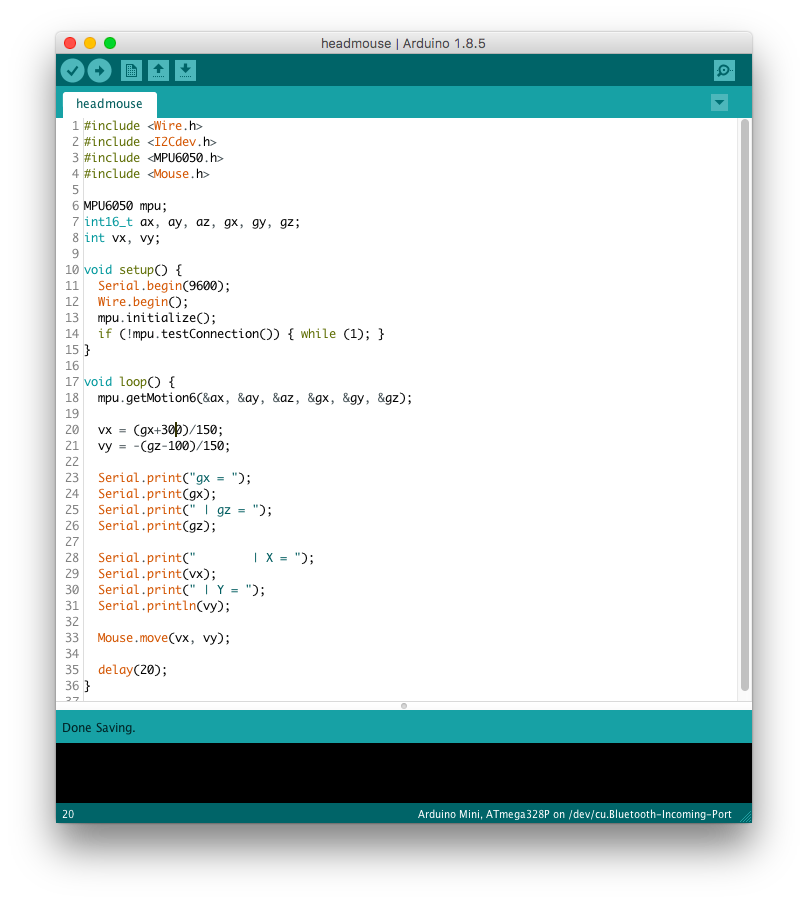
Link to the programme to use the PCB as a head mouse.. Gabry's page on making the head mouse with an Arduino Micro was a good place to refer for tips related to coding.
The I2Cdev.h library provides a simple interface for network communication between I2C devices. Here the communication is between the ATmega32U4 and MPU6050 sensor.
According to this description on MPU6050 sensor, "The devices combine a 3-axis gyroscope and a 3-axis accelerometer on the same silicon die together with an onboard Digital Motion Processor™ (DMP™) capable of processing complex 9-axis MotionFusion algorithms." The given link also provides a device library (MPU6050.h) which gives a simple interface to configure the sensor and derive the raw accelero/gyro readings. Refer to this link for the documentation on all the functions in this library.
To control the mouse, this Arduino library made my life much easier. As per the description, "The mouse functions enable 32u4 or SAMD micro based boards to control cursor movement on a connected computer through their micro’s native USB port."
(5)Testing
Video of the mouse pointer moving, corresponding to the sensor movement.