BACK

Week 12 - Output devices

It's Tuesday already and I am yet to solder the components on my board. I have spent a lot of time on the circuit design. I have also tried to understand the working of the bipolar stepper motor and Neil's code to control it. The milling process took longer than expected because of some errors at the machine which I have explained below. Hope to be done with this assignment by tomorrow.
Tuesday evening - I could run Neil's code and move the motor. However the anti-clockwise rotations are not smooth. Wonder why?

Wednesday - I noticed that the voltage regulator heated up when the board is connected to the ISP and to my PC. With the help of Lancy, our instructor, I figured out that the Vreg is reversed when the power supply is from the ISP. Lancy suggested that I add a diode to the path, so that current would flow only in one direction. It solved my issue!

I'm still figuring out how to exactly control the motor. Trying different codes..


1. PCB design
2. PCB production
3. PCB programming of the bipolar stepper motor

1. PCB design


Free HTML5 Bootstrap template
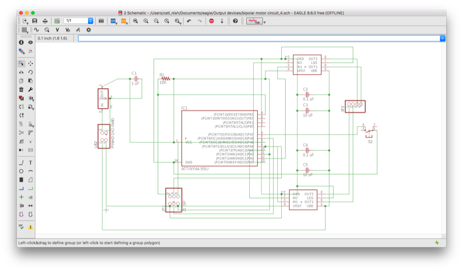
1. The circuit design is based on Neil's circuit in the course webpage. I have added a switch and changed the pin header to connect the motor from 2x2 to 1x4.
Free HTML5 Bootstrap template
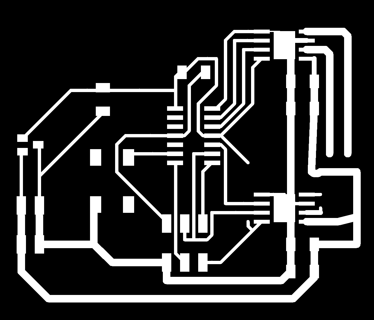
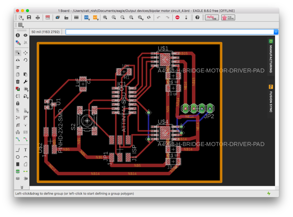
2. I autorouted the circuit (with the usual design rules: Clearances=16mil; Minimum width=18mil) first, followed by manually increasing the trace width to 30-40mil to handle the 12V motor.
Free HTML5 Bootstrap template
3. The traces to be milled.
Free HTML5 Bootstrap template
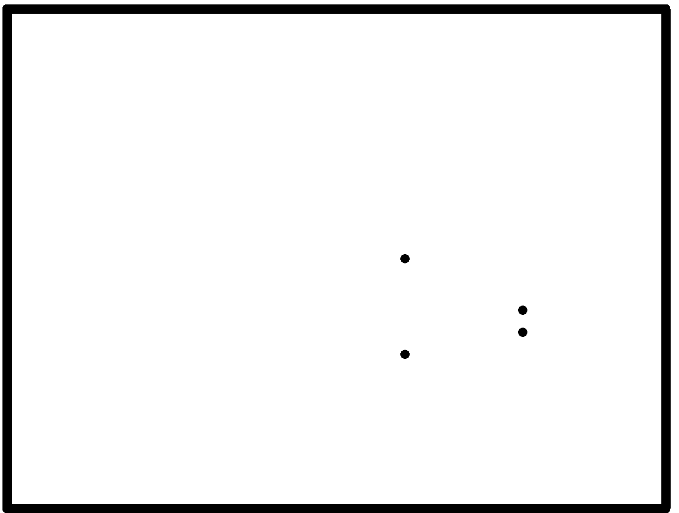
4. The PCB outline to be cut and four holes to be drilled for two jumper wire connections.

2. PCB production


Free HTML5 Bootstrap template
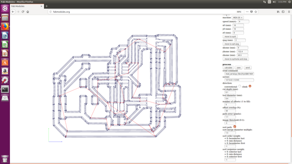
1. The tool path for the traces to be milled in the PCB using the 1/64in tool bit.
Free HTML5 Bootstrap template
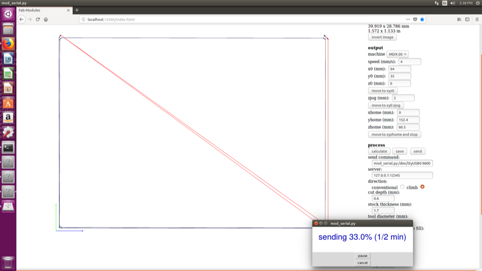
2. The toolpath for the PCB outline to be cut with the 1/32in tool bit.
Free HTML5 Bootstrap template
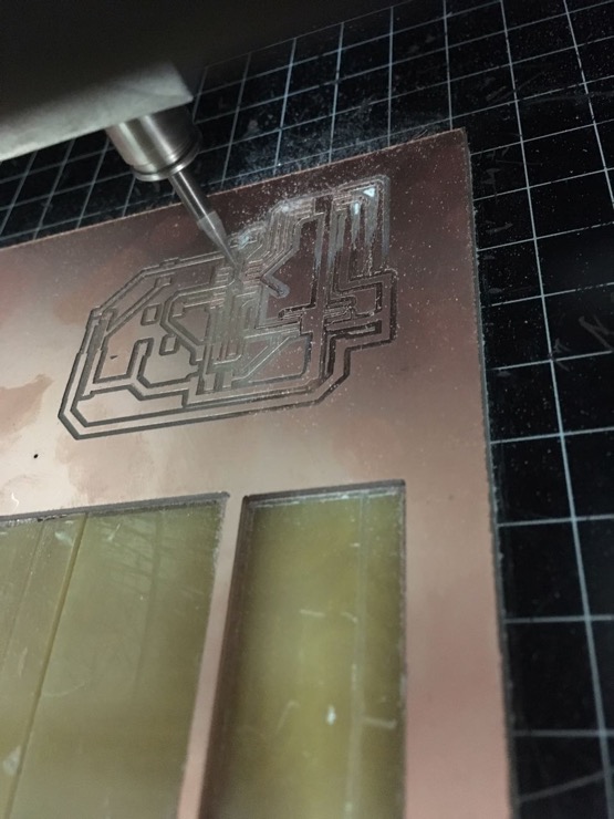
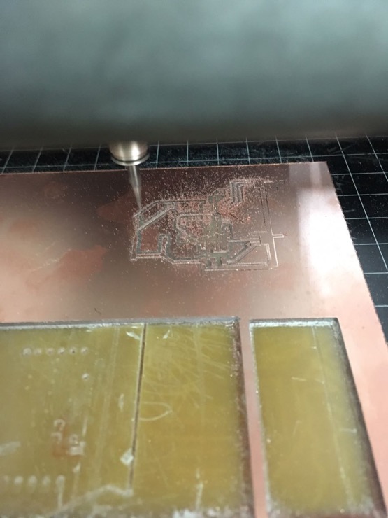
3. The machine bed was not totally flat. Hence the traces were not milled completely on one half of the PCB.
Free HTML5 Bootstrap template
4. I increased the Z-depth and tried milling along the same toolpath again. This time, since the tool used was a V-bit, it cut off perfectly on left half but took away too much copper from the right half of the PCB.
Free HTML5 Bootstrap template
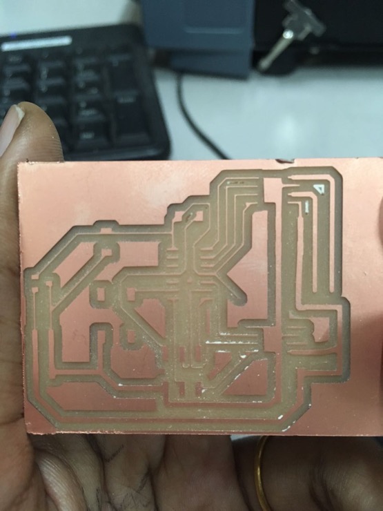
5. The traces on the right half of the board are too thin and hence may peel off when heated. I decided to mill another board.
Free HTML5 Bootstrap template
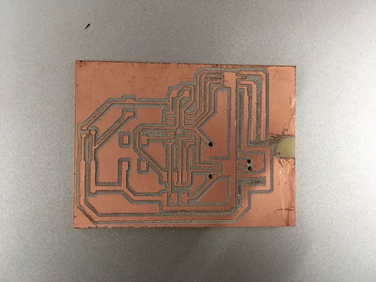
6. The board that I milled again was better but not the best. Probably because of a mediocre tool bit used. The holes were not drilled fully and I drilled them manually through using a broken tool bit. I had to cut off some copper to accomodate the 1x4 pin header to connect the motor.

3. PCB programming


A few datasheets that I referred to understand the working of the bipolar stepper motor : source1,source2, source3.

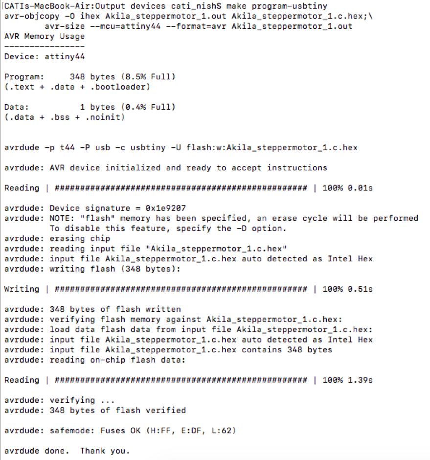
After checking if the board is fine with avrdude command, I flashed Neil's stepper motor code into the ATtiny44. The clockwise rotations looked fine (see video at the top of this page) but the anti-clockwise rotations did not.
I tried Rahul's code. The steps worked.
I then wanted to programme switch control of the motor. I tried this in Arduino IDE. I modified a code logic from an internet source to incorporate switch control. Frustratingly though, the switch worked only to pause the motor when the pin is held high in the code and switching would cut off the current. The other way where the pin is held low and switching would take it high and thus operate the motor, did not work. This is a puzzle yet to be solved. The code, however, worked beautifully for clockwise and anticlockwise rotations: ino file

Something else that I would like to document is my persisting problem with soldering. On two days, I was stuck with only one motor driver chip heating up and the other one idling. On each of those times, it was either one or the other chip not soldered properly. A lot of time wasted in debugging. Soldering is still my weakness.
Free HTML5 Bootstrap template
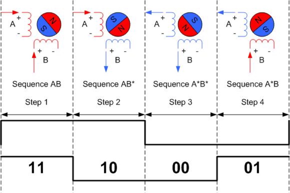
A figure from the internet that I used to understand and implement the coding logic. I am yet to study and understand full step (one/two phase), half-step excitation, microstepping etc.
Free HTML5 Bootstrap template
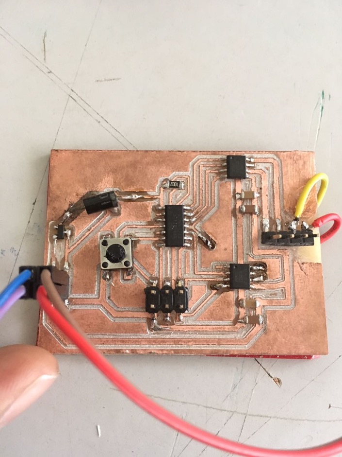
For the 4x1 pin header to connect to the motor, I had to design carefully, referring to which wires in the motor were coil pairs. One pair of coil terminals had to be connected to pins of the same motor driver chip. The other pair had to be controlled by the other driver chip.
Free HTML5 Bootstrap template
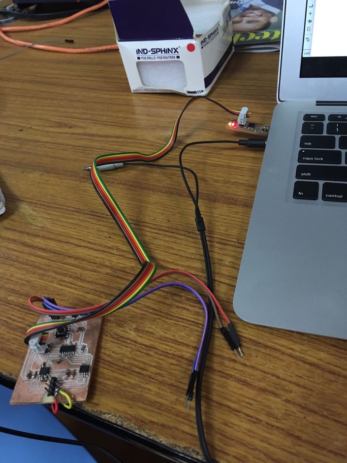
The makefile executed. The board is working fine.
Free HTML5 Bootstrap template
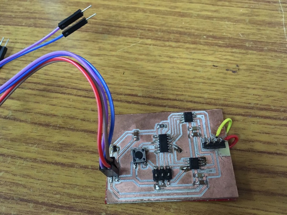
Jumper wires on the left to connect to the power supply. Jumper wires (yellow and red) on the right end of the board to complete the circuit routing.
Free HTML5 Bootstrap template
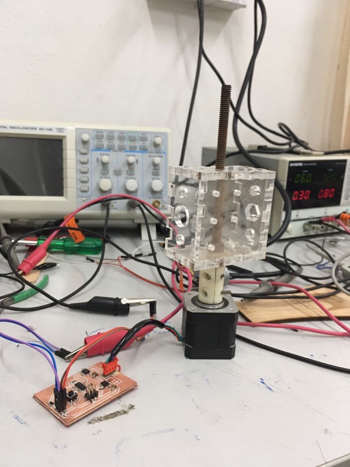
Using 12V and 0.5A power supply to operate the motor.
Free HTML5 Bootstrap template
Flashing different codes into the chip to check the motor control.

BACK