BACK

Week 11 - Input devices

A little milestone - I could solder the components without any mistakes in the first try. Felt accomplished. Figuring out the Python code and making it work was also not that difficult. Getting over the feeling of being overwhelmed by electronics. Looking forward to learning more...
1. Group assignment: measure the analog levels and digital signals in an input device
2. PCB production
3. PCB programming


A few video clips of the process...

1. Group assignment: measure the analog levels and digital signals in an input device


Free HTML5 Bootstrap template
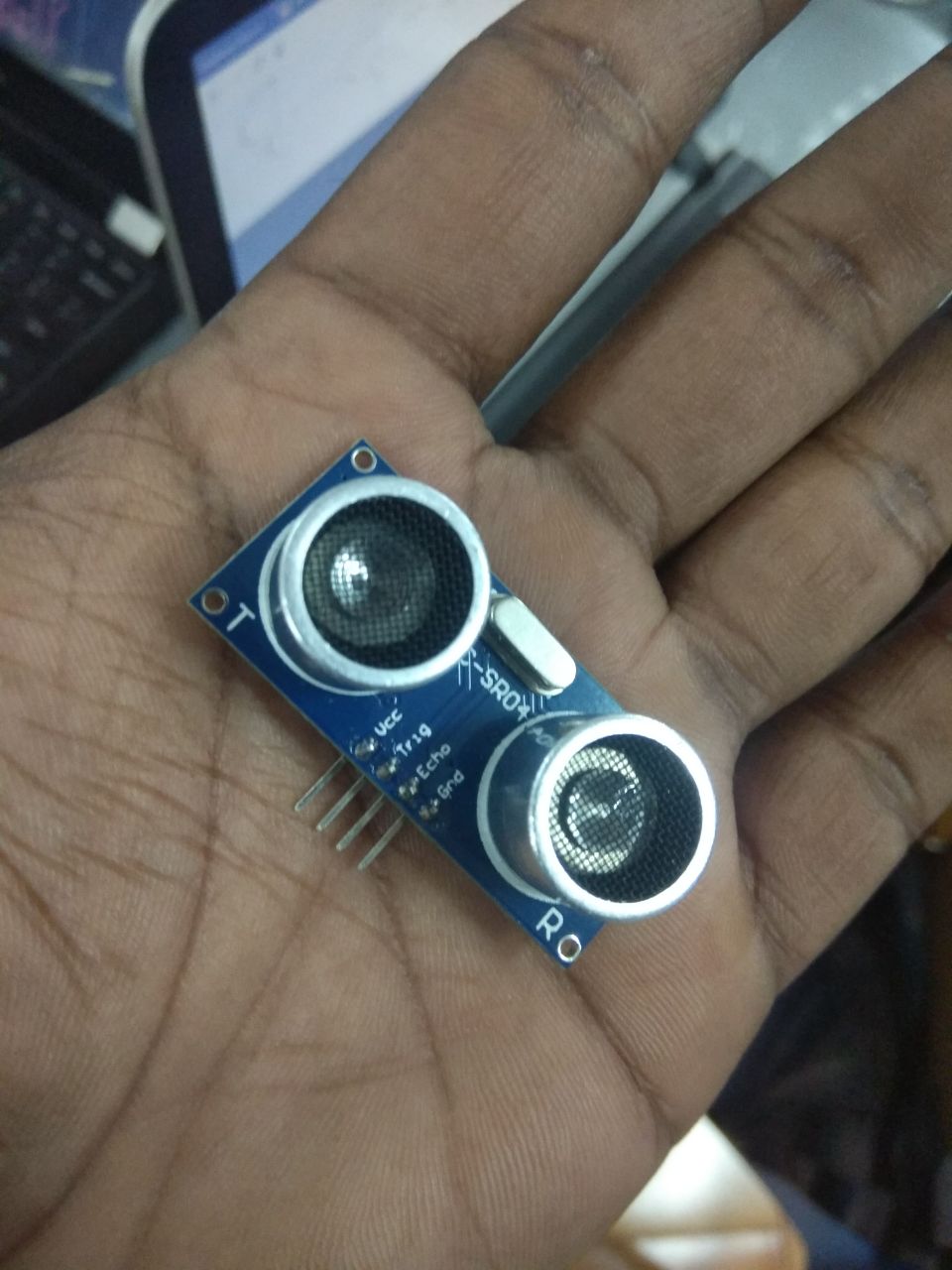
1. The HC-SR04 ultrasonic sensor module which can emit ultrasound at 40000Hz. The wave travels through the air and on hitting an object, it bounces back to the module. The travel time and speed of the echo wave will help to calculate the distance of the object from the module.
Free HTML5 Bootstrap template
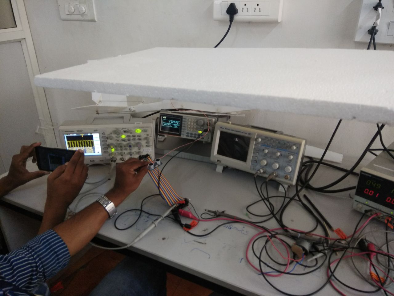
2. 5V DC supply was connected to the VCC pin on the sensor.
Free HTML5 Bootstrap template
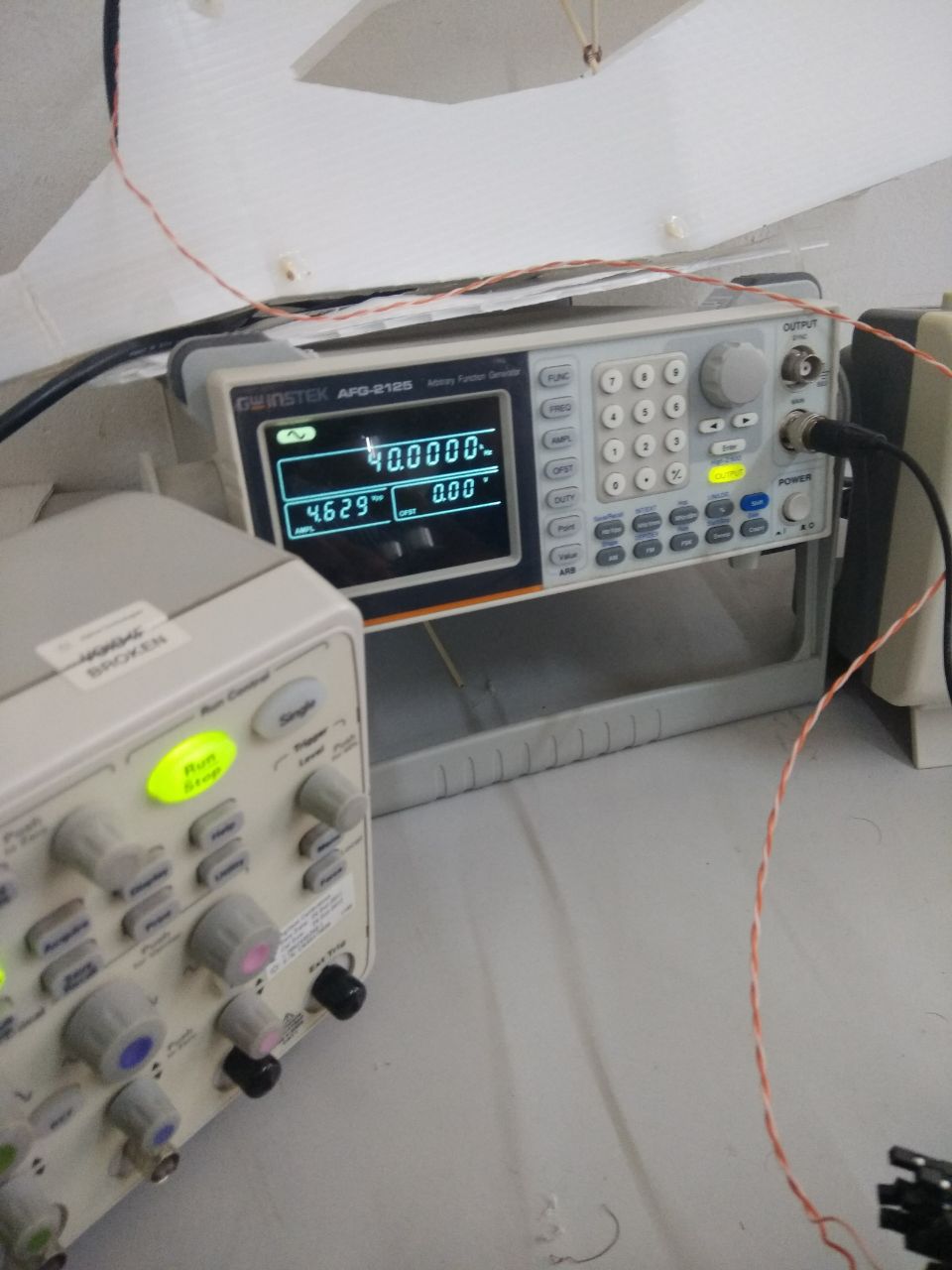
3. The function generator was used to generate a signal of frequency 40000Hz and its ouput was connected to the Trig pin on the ultrasonic sensor.
Free HTML5 Bootstrap template
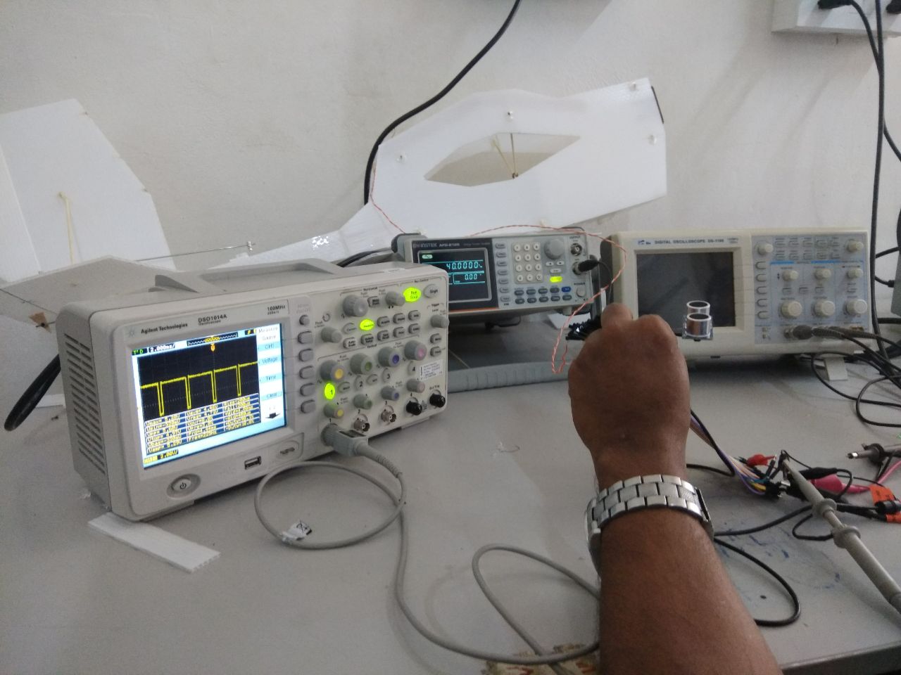
4. The oscilloscope was connected to the Echo pin of the sensor to measure the returning pulse.
Free HTML5 Bootstrap template
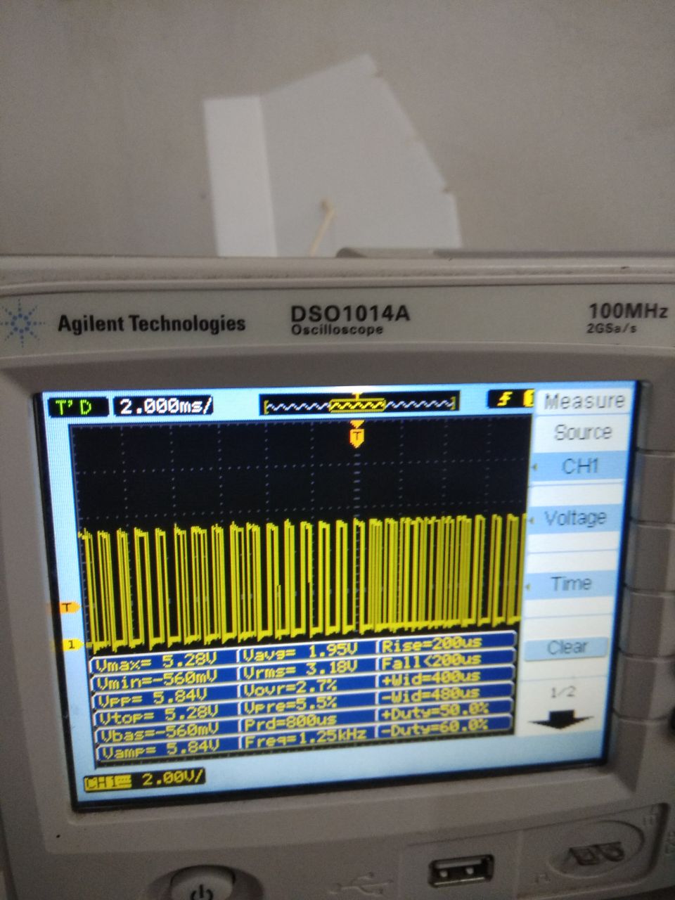
5. When the object is closer to the sensor, the pulse width is smaller, corresponding to the travel time taken by the echo signal.
Free HTML5 Bootstrap template
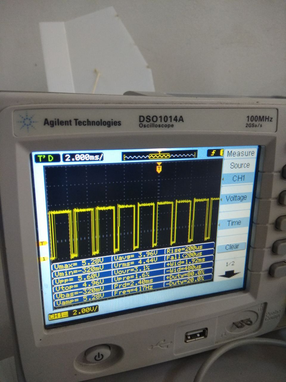
6. The pulse width is larger when the object is further away from the sensor.
Free HTML5 Bootstrap template
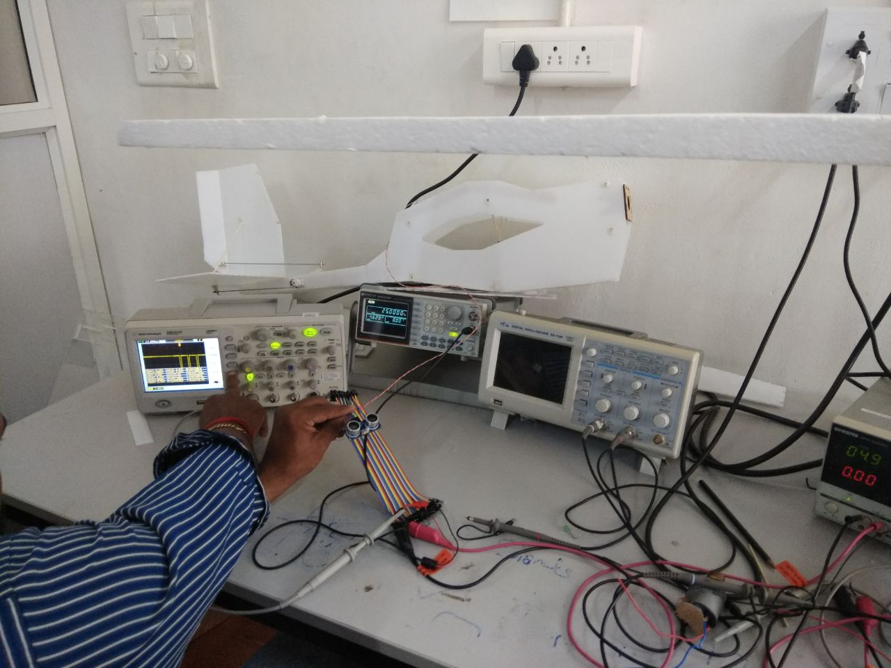
7. A sheet of thermocol is held above the sensor and its distance is varied to check the pulse width of the echo signal.
Free HTML5 Bootstrap template
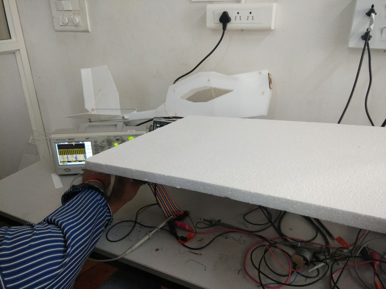
8. When the sheet is held closer to the sensor, the pulse width is smaller.

2. PCB production


I made a temperature sensing board. Neil had explained two types of temperature sensors - NTC (Negative Temperature Coefficient) and RTD (Resistance Temperature Detector). This page summarizes the differences between the two types of temperature sensors.

I tried making the NTC thermistor board, which, according to Neil, is preferred for lower temperature applications. I referred to Neil's board to design my board using Eagle.

Download the design files for the PCB here:
Schematic
Board
Traces for milling
Outline for cutting

Free HTML5 Bootstrap template
The circuit is a 'Wheatstone brige' with 3 fixed value resistors and 1 variable resistor, which is the thermistor. When the 4 resistors are balanced, there is no current flow. A temperature change will change the resistance of the thermistor and initiate current flow.
Free HTML5 Bootstrap template
The schematic of the circuit in Eagle.
Free HTML5 Bootstrap template
The design of the board in Eagle.
Free HTML5 Bootstrap template
Milling and cutting the board in Modela MDX-20 milling machine.
Free HTML5 Bootstrap template
The components to be soldered on the board.
Free HTML5 Bootstrap template
The board after soldering.
Free HTML5 Bootstrap template
Holding the multimeter pins across the Vcc and GND pins of the chip displays a value of around 5V.

3. PCB programming


Setting up Python3 and installing the required modules in the right place in my Mac was a bit of a job. But felt good when it was done.
Download the programme files here:
Makefile
C file
hex file to be flashed into the ATtiny45
Python3 file to visualize the sensor output on PC (GUI)
Python3 file to visualize the sensor output on PC (IF-ELSE)

Free HTML5 Bootstrap template
1. Using the ISP programmer I made in week 5 (electronics production) to flash the .C programme into the Attiny45.
Free HTML5 Bootstrap template
2. For AVR microcontrollers, the avr-gcc to compile the C code and the avrdude to send the program to the chip are contained in the Makefile.
Free HTML5 Bootstrap template
3. I had to rename the makefile to 'Makefile' without the .make extension. Even after renaming, the .make extension kept showing up in the title bar of Xcode along with the file name and the make command would not work. This was resolved by renaming the file from the Terminal using 'mv Makefile.make Makefile'.
Free HTML5 Bootstrap template
4. With the 'make' command the first four lines of the Makefile are executed which are : name of the file to compile, extension of the file to compile, microcontroller to program and the frequency of the board to program.
Free HTML5 Bootstrap template
5. make program-usbtiny failed in the first attempt due to wrong orientation of the multi-pin connecting the ISP programmer and board.
Free HTML5 Bootstrap template
6. With the right connections, make program-usbtiny command executes the avrdude command to send the .hex program to the chip.
Free HTML5 Bootstrap template
7. Use the FTDI 5V serial cable to connect the board to the PC through USB.
Free HTML5 Bootstrap template
8. Error because pyserial module is not installed.
Free HTML5 Bootstrap template
9. Installing pyserial module using pip command.
Free HTML5 Bootstrap template
10. I had to add parantheses to the statement after print command to adapt the code from Python2 to Python3.
Free HTML5 Bootstrap template
11. I had to install Tkinter, which is a GUI package.
Free HTML5 Bootstrap template
12. Installing tcl and tk packages, followed by testing tkinter import.
Free HTML5 Bootstrap template
13. I had to install Numpy, which is a Python library support for large, multi-dimensional arrays and matrices, along with mathematical functions to operate on these arrays.
Free HTML5 Bootstrap template
14. python3 -m serial.tools.list_ports listed the available two ports.
Free HTML5 Bootstrap template
15.Error when the port ID is not passed in as an argument to the code.
Free HTML5 Bootstrap template
16. Passing in the port ID as argument into the code with the python3 command, followed by filename.
Free HTML5 Bootstrap template
17. The list of thermistors and the B value. I used NHQ103B375T10 and its B value is 3750, which is used in the code to calculate the temperature based on the resistance value.
Free HTML5 Bootstrap template
18.The equation relating B (beta) value with temperature and resistance. Rt1 and Rt2 are resistance values at temperatures T1 and T2 respectively.
Free HTML5 Bootstrap template
19. Exploring the code and editing the size of the box.
Free HTML5 Bootstrap template
20. The tkinter GUI displaying the temperature value. The video at the top shows the sensor in action.
Free HTML5 Bootstrap template
21. Changing the colours in the GUI.
Free HTML5 Bootstrap template
22. The edited GUI.
Free HTML5 Bootstrap template
23. Editing the code with an 'IF-ELSE' statement to display different messages above or below 24 degree C.

BACK