Objectives
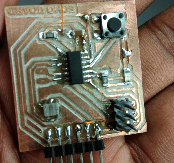
ATtiny 44 Board
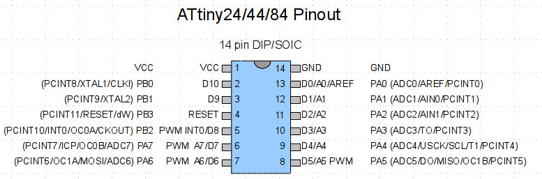
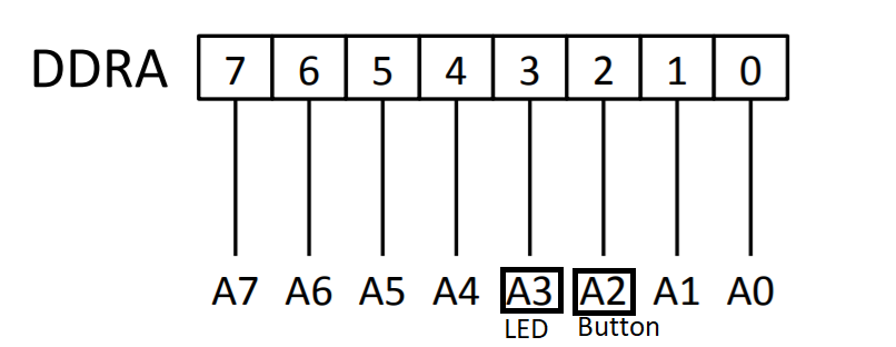
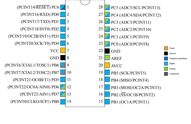
The chip has two ports , PORT A and PORT B. Port A has 8 pins and Port B has 4 pins. In my connection led is connected to PIN 10(PA3) and switch is connected to PIN 11 (PA2).
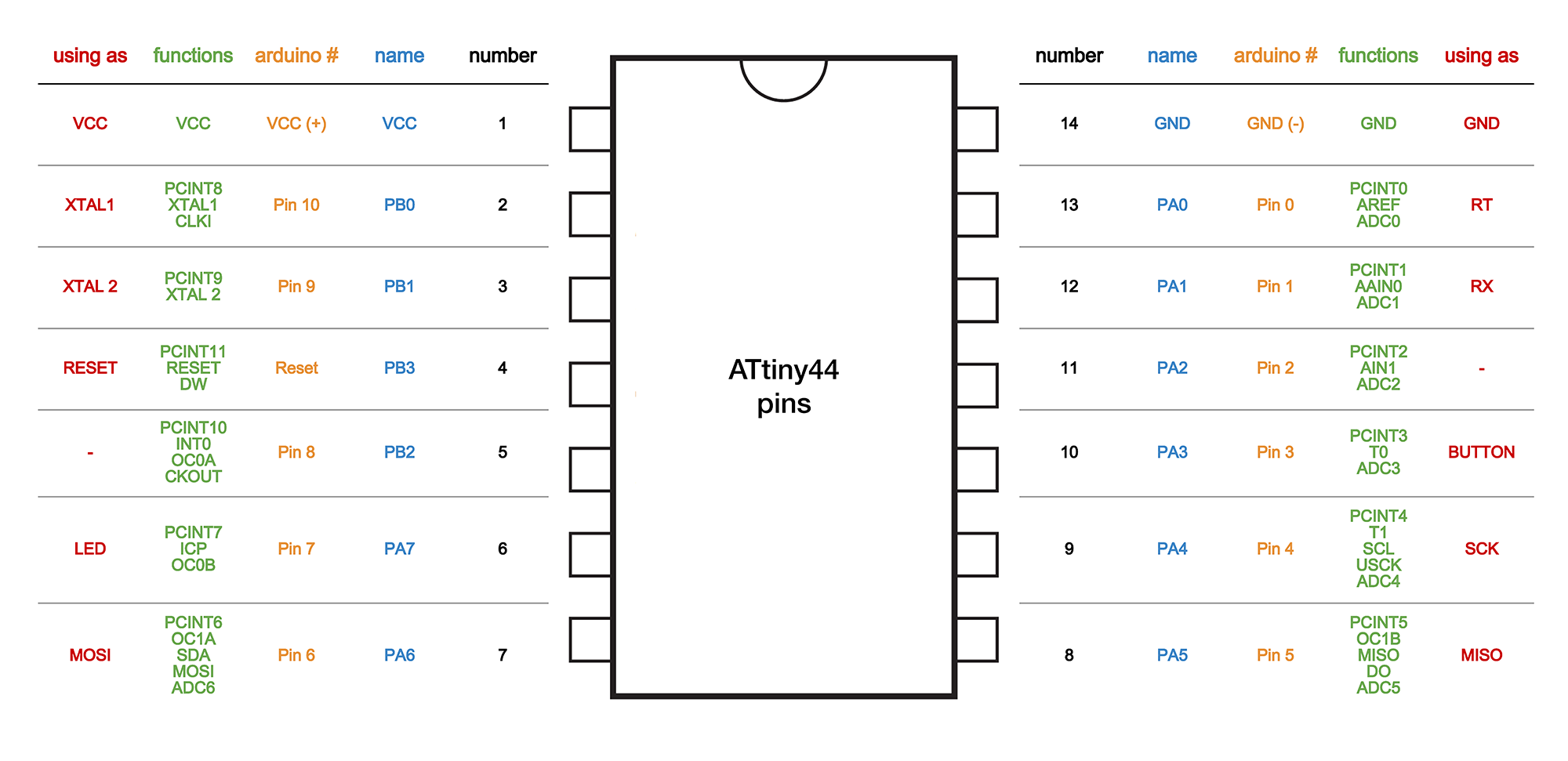
This image above really explains the Pin Structure, taken from Ines Ariza Page
Few Characteristics of ATtiny44 are :
Architectural Overview
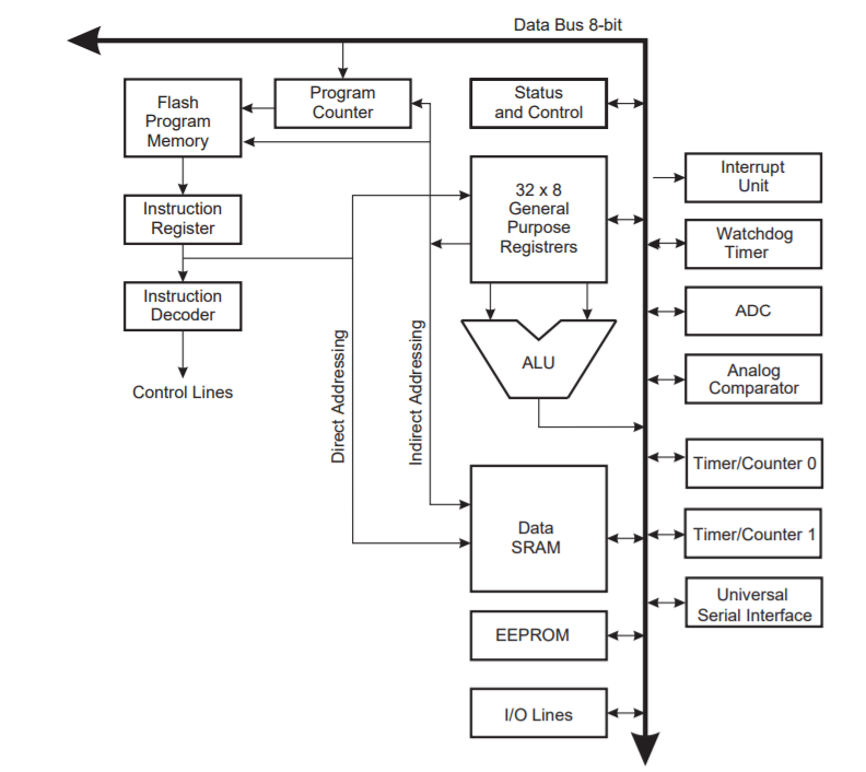
In order to maximize performance and parallelism, the AVR uses a Harvard architecture with separate memories and buses for program and data. Instructions in the Program memory are executed with a single level pipelining. While one instruction is being executed, the next instruction is pre-fetched from the Program memory. This concept enables instructions to be executed in every clock cycle. The Program memory is In-System Reprogrammable Flash memory.
Changes to my board
This week we have to try different programs on the ATtiny 44 microcontroller involving the LED and the Switch in the board. I first tried the LED blink program with my USBtiny. But the LED was not blinking, i was afraid that there is a problem with the circuit. The previous week of Electronic Design, it took a lot of time on hacking my board to make it work.
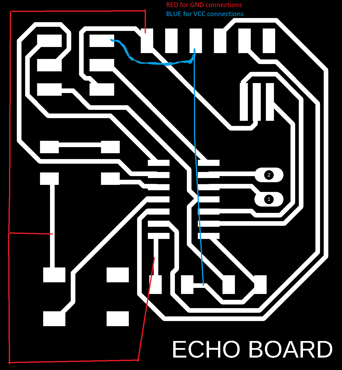
So i sit with my board for hours to solve the issue. My circuit was okay and all the connections were correct. Then I tried changing my jumper wires to lookout for voltage leaks.
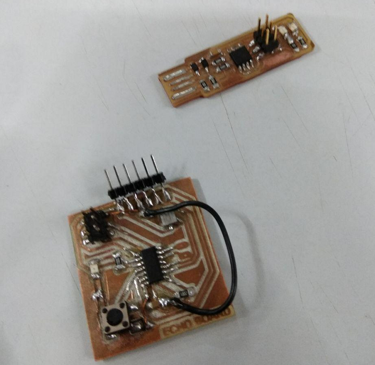
Atlast i found the problem, actually the LED blinking program was working and the LED was blinking even from the start, only thing is that the LED was blinking with very little voltage to be exact just 1.2 V. So out of 5V only 1V is only gets to my LED, and thats when i noticed that i had an orange LED. Someone had placed an orange LED between the Red Leds in the pack at our storing place and i have placed a 499 ohm Resistor corresponding to the Red Led. So now as i have an orange LED, i have to change my Resistor value, i choose 100 ohm Resistor this time. And atlast my Led was blinking, and i felt happy and relief.
Embedded Programming
Some Basics I learned
Some C operators
Eg. 10100111 | 11000101 = 11100111
Eg. 10100111 & 11000101 = 10000101
Eg. ~10100110 = 01011001
I/O
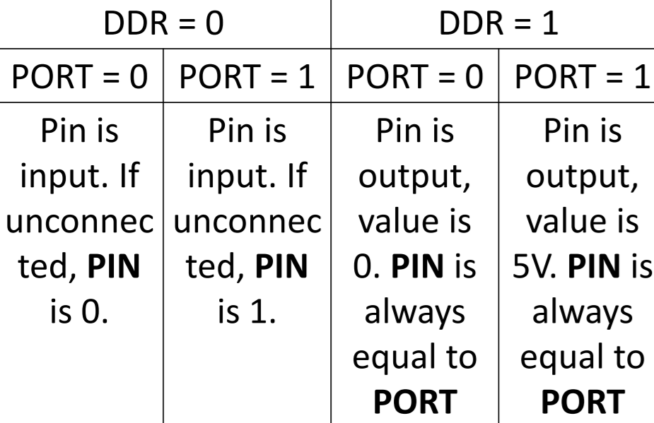
DDR (Data Direction Register)
Setting Register Values
Interpretation of DDR values
PORT Register
PIN Register
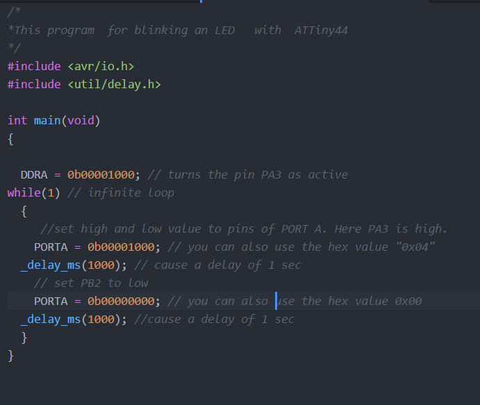
LED Blink Program using C
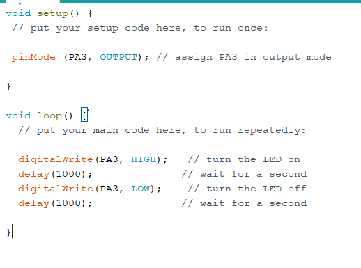
I have my LED connected to PA3 and Switch to PA2
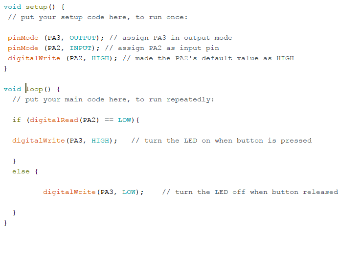
Programming using Arduino
First download and install Arduino IDENow change the preferences and add the below link to include ATtiny details in the additional board manager library
https://raw.githubusercontent.com/damellis/attiny/ide-1.6.x-boards-manager/package_damellis_attiny_index.json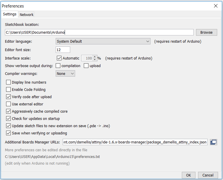
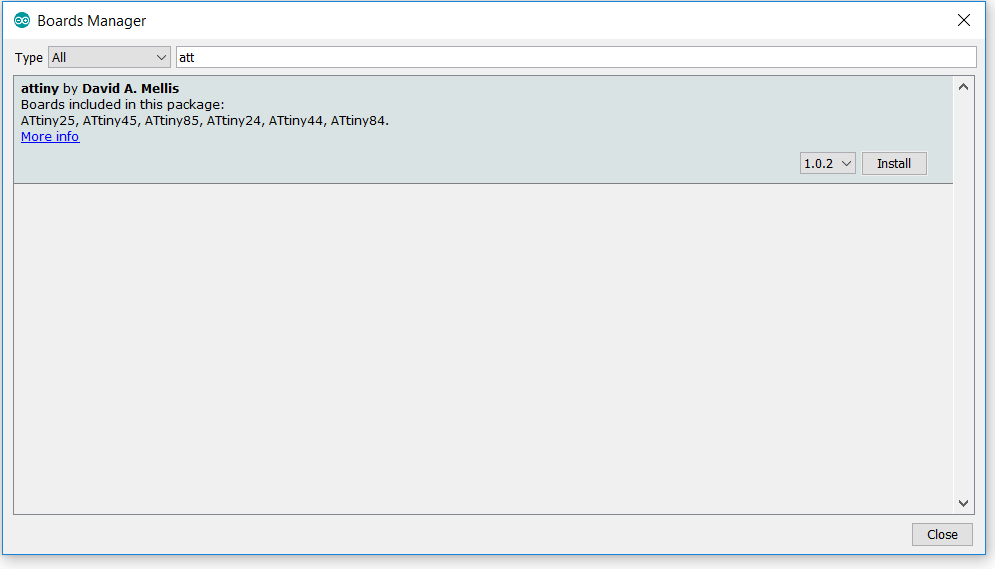
Go to the Tools> Boards> Boards Manager and search for attiny, and download the ATtiny 44 files to the library
After installing the Attiny files, go to the Tools> Boards > and select Attiny 44 from the list
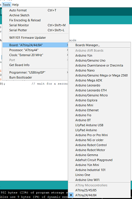
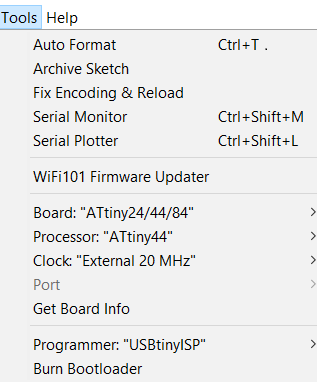
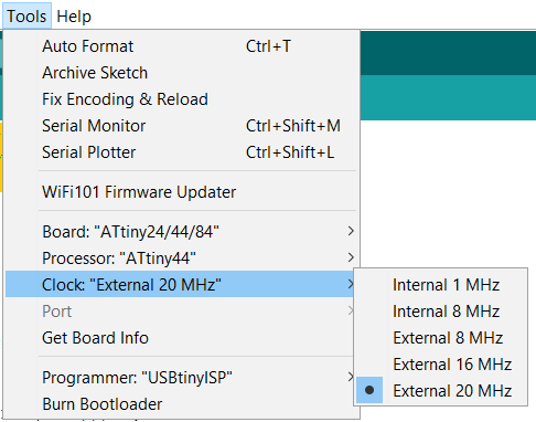
We have to now provide other details of our Board, in Tools select the programmer as USBtiny , the processor as ATtiny44 and the clock as External 20 Hz
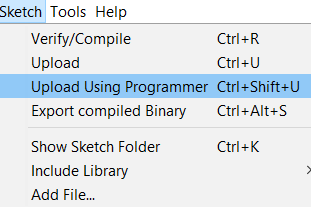
Now verify your program, then compile it and select upload the program using Programmer
LED Blinking Program
See the video below
Switch and LED Program
See the below video
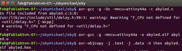
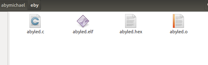
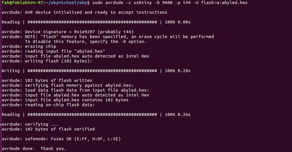
Download VideoProgramming using AVR GCC Compiler
Open the terminal from your C file folder and type the following commands with your program name preciding the .c , .o , .elf and .hex
avr-gcc -g -Os -mmcu=attiny44a -c abyled.cavr-gcc -g -mmcu=attiny44a -o abyled.elf abyled.o
avr-objcopy -j .text -j .data -O ihex abyled.elf abyled.hex
Programming C in Atmel Studio
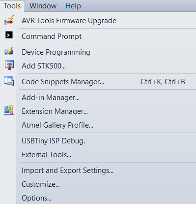
First download and install Atmel Studio Atmel Studio Now go to Tools > Extenal Tools and add the USBTiny Debug by filling the following
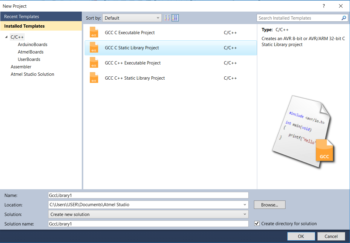
Open a new project and select the preferences
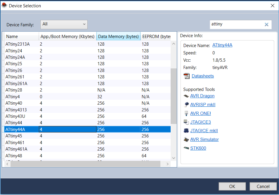
Then add the Attiny 44
Type your program in the tab
Program for toggle switch
Download Program File#include < avr/io.h> #define F_CPU 20000000 #include < util/delay.h> int main(void) { DDRA =0b00000100; PORTA =0b00001000; while(1) { if(!(PINA & (1<<3)) { PORTA |= (1<<2); } else { PORTA &= (0<<2); } } }
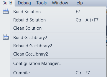
Now go to Build > Build Solutions to Compile and get the Hex file
Go to Tools > USBTiny Debug and Program the board
Assembly Language Programming
Toggle Switch and LED
;Author Aby Michael 20-03-2018
;Led is connected to PortA 3
;Switch is connected to PORTA 2
.device attiny44
.org 0
sbi DDRA,3 ;Set bit , 3rd bit of DDRA is set , so PA3 is output
cbi DDRA,2 ;Clear bit , 2nd bit of DDRA is set , so PA2 is input
sbi PORTA, 2 ; the input bit is internally pulled up
main:
SBIC PINA,2 ;
cbi PORTA,3 ;
SBIC PINA, 2 ;
RJMP main ;jump to main
sbi PORTA,3 ;set the 3rd bit ,means digital high at output pin
RJMP main ;jump to main

Group Assignment
Comparing the performance and development workflows for other architectures
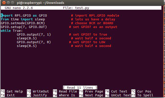
Raspberry pi
Raspberry pi is a small single board computer that is designed to teach basic computer skills for school students in developing countries. They are used in various fields with wide range of applications.
Programming
ATmega328/P
The Atmel ATmega328/P is a low-power 8-bit microcontroller based on the AVR enhanced RISC architecture. By executing powerful instructions in a single clock cycle, the ATmega328/P achieves throughputs close to 1MIPS per MHz( very efficient than ATTiny44). This empowers system designer to optimize the device for power consumption versus processing speed.
Features
High Performance, Low Power Atmel AVR 8-Bit Microcontroller Family
Memory
Comparing ATtiny44 and Atmel mega 328
Conclusions
The Week was very good, i could almost go through and study a wide range of programming languages and softwares.
This work by Aby Michael is licensed under a Creative Commons Attribution-NonCommercial-ShareAlike 4.0 International License.
